BRUEL & KJAER PHOTON+ Parts list manual

Information in this document is subject to change without notice. No part of this
document may be reproduced or transmitted in any form or by any means, electronic or
mechanical, for any purpose, without the express written permission of Brüel & Kjær
Sound & Vibration Measurement A/S (“Brüel & Kjær”).
By installing, copying or using the Software, the user agrees to be bound by the terms
of the Brüel & Kjær End User License Agreement which is a legally binding
agreement between the user (“the Licensee”) and Brüel & Kjær for the Brüel & Kjær
software, which includes software components and tools, and written documentation
(“Software”).
Brüel & Kjær makes no warranties on the Software, whether express or implied, nor
implied warranties of merchantability or fitness for a particular purpose. Brüel &
Kjær does not warrant your data, that the software will meet your requirements, or that
the operation will be reliable or error free. The Licensee of the Software assumes the
entire risk of use of the Software and the results obtained from use of the software.
Brüel & Kjær shall not be liable for any incidental or consequential damages, including
loss of data, lost profits, cost of cover or other special or indirect damages.
Copyright 2013. Brüel & Kjær Sound & Vibration Measurement A/S. All rights
reserved
All trademarks and registered trademarks are the property of their respective holders.

Table of Contents
Table of Contents
1Introduction............................................................................................................. 1
System Description................................................................................................... 1
Options...................................................................................................................... 2
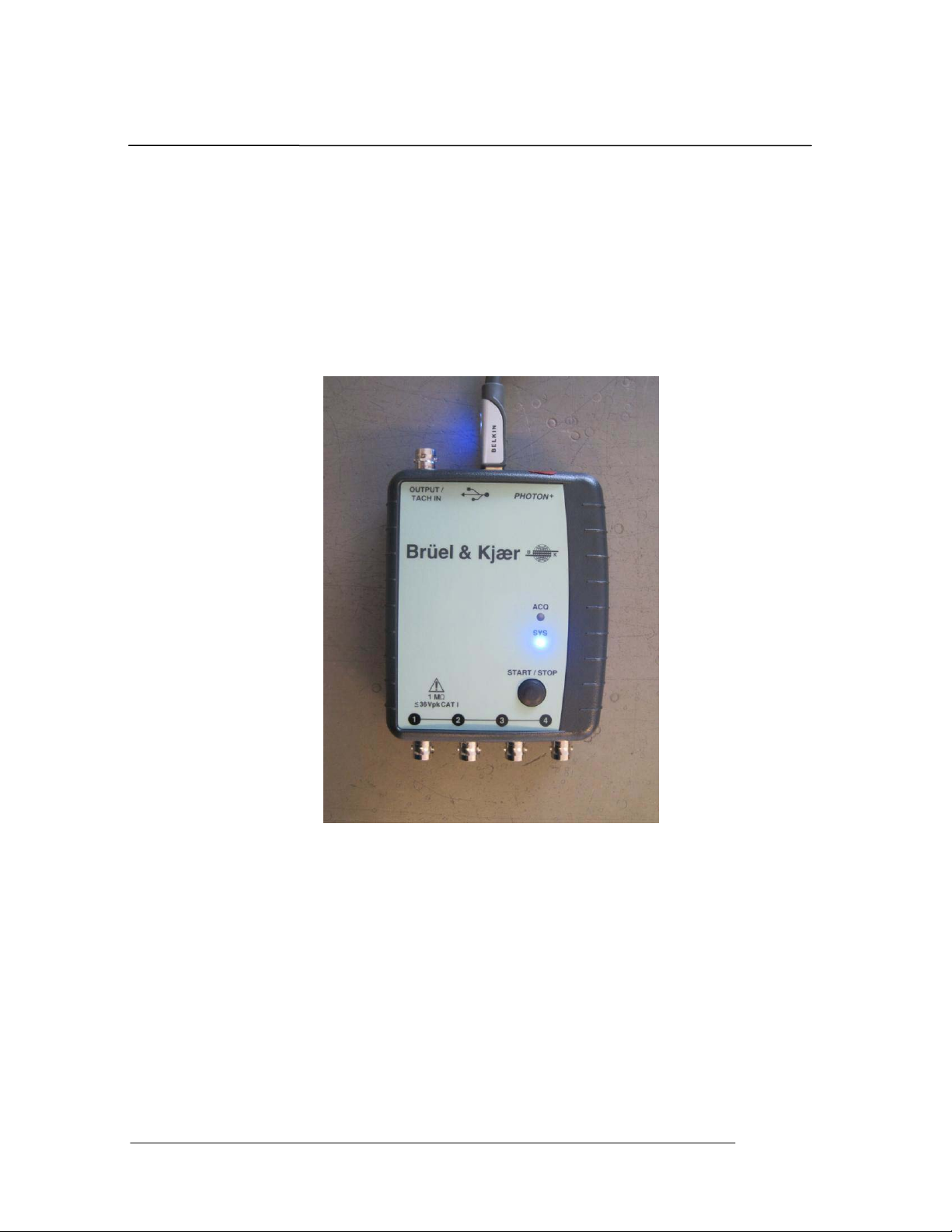
System Hookups and Status Indicators..................................................................... 2
Specifications............................................................................................................ 5
2Safety and Equipment Protection.......................................................................... 7
Safety Summary........................................................................................................ 7
Danger Warnings...................................................................................................... 8
3Power and Environmental Requirements............................................................. 9
Power Requirements................................................................................................. 9
USB Cable Requirements ....................................................................................... 10
Environmental Requirements.................................................................................. 10
Operation ................................................................................................................ 10
Storage and Shipment ............................................................................................. 10
Packaging for Shipment.......................................................................................... 10
4SystemInstallation................................................................................................ 12
Step 1: PHOTON+ Driver Installation Instructions ................................................ 13
Step 2: Installing Application Software on the PC.................................................. 13
Step 3: Running the RT Pro Software..................................................................... 13
Uninstall the Device Driver..................................................................................... 15
5Maintenance.......................................................................................................... 16
6Calibration............................................................................................................. 17
What Do We Calibrate?.......................................................................................... 17
Signal Source Used for Calibration......................................................................... 17
Calibration Tools .................................................................................................... 18
Install the Calibration Software .............................................................................. 19
Calibration Procedure ............................................................................................. 19
Calibration Data File and Report............................................................................. 29
7SystemTroubleshooting....................................................................................... 30
USB not connected at application startup................................................................ 30
Check if USB driver is installed correctly............................................................... 31
Failure to initialize the PHOTON+......................................................................... 33
USB cable disconnected while operating software.................................................. 33
Inadequate Power Supplied to the PHOTON+....................................................... 34
Windows Application Software Failure.................................................................. 35
8Limited Warranty Statement............................................................................... 36
Index....................................................................................................................... 38
PHOTON
+
System Guide 1


Introduction
PHOTON+ System Guide
1
1 Introduction
This manual provides instructions on installing, maintaining, and
calibrating a PHOTON+ Dynamic Signal Analysis System. It also
provides information on power and environmental requirements
and safety considerations. Any person responsible for installing,
maintaining or calibrating the system should be fully familiar with
the contents of this manual. For instructions on using the system
refer to the “RT Pro Dynamic Signal Analysis Series.”
Other sections of this manual cover:
Power and environmental requirements
Safety
Installation
Maintenance
Calibration
Troubleshooting
System Description
PHOTON+ makes any PC an instrument-quality analyzer that is a flexible
multi-channel system for noise and vibration analysis. Designed for
realtime signal analysis, the PHOTON+ offers remarkable performance with
a measurement dynamic range of 110 dB and an 84.2 kHz real-time rate.
Signal analysis applications are available for the range of noise and
vibration testing – realtime spectrum analysis, modal data acquisition,
realtime octave analysis, order tracking and waterfall analysis, transient
capture and SRS analysis, swept sine analysis. The PHOTON+ can also be
used for data recording and post analysis. The PHOTON+ System comes
standard with two inputs with CCLD sensor power, an output signal
source, a storage case, a 6’ (1.83 m) USB Type A to Type B cable, a user

Introduction
PHOTON+ System Guide
2
manual (on CD), installation CD, calibration data CD, and a one year
warranty covering parts and labor.
Options
There are both hardware and software options available for the
PHOTON+. These options are listed in the table below.
HardwareOption
One extra analog input
Description
Two inputs standard, expandable to four inputs
Real-Time Software Options
RT Pro
Description
Signal analysis and waveform source functions
Modal Data Acquisition Compute FRF for modal analysis
Acoustic Data Acquisition Realtime octave analysis
Order Tracking and Analysis Order tracking and waterfall analysis
Environmental Data Reduction
Transient capture and SRS analysis
Swept Sine Analysis Swept Sine analysis with digital tracking filters
LongWaveformRecording Gap free streaming of data to disk
Calibration In-house System Calibration
Post Processing Options
RT Pro Playback
Description
Time and frequency domain signal analysis
Acoustic Analysis Playback Post processed octave analysis
Order Tracking Playback Post processed order tracking and waterfalls
Environmental Data Reduction Post processed SRS synthesis
Sound Quality Analysis Data editing and sound quality metrics
Data Recorder Options
Data Recorder software
Description
RT Pro data recorder with voice channel
System Hookups and Status Indicators
The front of the system has 4 BNC connectors. These connectors are
labeled 1 through 4 and are for connection to analog voltage signals. The
back of the system has 1 BNC connector labeled OUTPUT/TACH IN.
When Output functionality is used, the connector supplies an analog output
signal to drive devices such as electrodynamic shakers. The Output can also
be switched from an Output to a tachometer input. The back of the system is
also the location of the USB connector.

Introduction
PHOTON+ System Guide
3
Warning
Do not connect analog voltage signals exceeding
+36 Volts to the input channel or the system
electronics may be damaged.
Front view of the PHOTON+ showing the BNC Connectors for Four Input Channels
Rear view of the PHOTON+ showing the BNC connector forOutput/Tach-in and the
USB Cable Port.

Introduction
PHOTON+ System Guide
4
Two LED’s on the top of the unit provide status indication:
ACQ – flashes when the system is acquiring data.
SYS – lit when the DSP is powered.
The START/STOP button can be used to remotely start or stop
a measurement (when using RT Pro software)
Top view of the PHOTON+ showing the ACQ LED, SYS LED, and
START/STOP button.

Introduction
PHOTON+ System Guide
5
Specifications
Inputs
Analogchannels
Two standard, expandable to four channels. All are differential inputs with
1M Ohm impedance. Setup allows per channel selection of gain (x0.01, .0.1,
x1, x10), transducer sensitivity, sensor type (e.g., acceleration, force, pressure,
etc.), and coupling (AC, DC, CCLD).
Electronics
Differential amplifier, programmable gain amplifier, anti-aliasing filters, and
24-bit Analog to Digital Converter (ADC).
Filtering
An analog filter at 300 kHz plus a 160 dB/octave linear-phase digital filter
prevent aliasing and phase distortion.
Frequency range
Up to 84.2 kHz analysis frequency (192 k samples per second).
Voltage range
+10 Vpeak
Signal conditioning
Voltage or CCLD sensor power (2.4 mA, 22 Vpeak open circuit)
Maximuminput
+36 Vpeak without damage
Resolution
24-bit
Dynamic range
115 dBfs (two tone test, 100 linear averages)
Accuracy
±0.04 dB (1 kHz sine at full scale)
Channel match
Amplitude
Phase
Within +0.04 dB
Within +0.5 degree
(from DC to 21 kHz, frequency response measurement, both inputs on the
same input range, linear average)
Aliasprotection
>117 dB stopband rejection
Signal-to-noise
>90 dB (from DC to 1000 Hz measured with half-full-scale sine wave).
Frequency accuracy
Within0.01%
Output
Analogchannels
WaveformSource standard.
Electronics
24-bit Digital to Analog Converter (DAC) with anti-imaging filter.
Filtering
A 160 dB/octave digital filter plus an analog filter prevent imaging and phase
distortion.
Frequency range
Up to 42 kHz output frequency (96k samples per second).
Voltage range
+10 Vpeak
Resolution
24-bit
Dynamic range
110 dBfs
Outputimpedance
50
Maximumcurrent
24 mA
peak
All Specifications subject to change without notice.

Introduction
PHOTON+ System Guide
6
Regulatory Compliance
Compliance
CE
1
Marking
Safety
EN
2
61010-1, CAT 1 Pollution Degree 2
EMC
FCC
4
Part 15 (CFR 47) Class A, EN 61326 Class A,
CISPR22
5
Class A
1CE = European Compliance.
2EN = European Norm.
3IEC = International Electrotechnical Commission.
4FCC = Federal Communications Commission.
5CISPR = International Special Committee on Radio Interference.
European Community Statement
This equipment complies with the following European directives:
EMC Directive 89/336/EEC and amending Directives 92/31/EEC and 93/68/EEC
Low Voltage Directive 73/23/EEC.
FCC Class A Statement
This equipment has been tested and found to comply with the limits for a Class A
digital device, pursuant to Part 15 of the FCC Rules.
These limits are designed to provide reasonable protection against harmful
interference when operated in a commercial environment.
This equipment generates, uses, and can radiate radio frequency energy and, if not
installed and used in accordance with the instruction manual, may cause harmful
interference to radio communications.
Operation of this equipment in a residential area is likely to cause harmful
interference, in which case, the user will be required to correct the interference at his
own expense.
Any changes or modifications to this equipment not expressly approved by Brüel &
Kjær could void the user's authority to operate this equipment.
All Specifications subject to change without notice.

PHOTON+ System Guide
7
Safety and Equipment Protection
2 Safety and Equipment Protection
Safety Summary
The following general safety precautions must be observed during all
phases of operation, maintenance, and calibration of this system.
Failure to comply with these precautions or with specific warnings
elsewhere in this manual violates safety standards or design,
manufacture, and intended use of this system. Brüel & Kjær
assumes no liability for the customer’s failure to comply with these
requirements.
Do Not Operate In an Explosive Atmosphere
Do not operate the system in the presence of flammable gases or fumes.
Operation of any electrical instrument in such an environment constitutes
a definite safety hazard.
Keep Away From Live Circuits
Operating personnel must not remove the system cover. Qualified
service personnel must make component replacement and internal
adjustments. Do not replace components with power cable connected.
Under certain conditions, dangerous voltages may exist even with the
power cable removed. To avoid injuries, always disconnect power and
discharge circuits before touching them.
Do Not Substitute Parts or Modify the System
Because of the danger of introducing additional hazards, do not install
substitute parts or perform any unauthorized modification to the system.
Return the system to Brüel & Kjær for service and repair to ensure that
safety features are maintained.

PHOTON+ System Guide
8
Safety and Equipment Protection
Danger Warnings
The warning messages below, and throughout this guide, are important
notices regarding safe system operation and system protection.
Instructions given by these warning must be followed to ensure safety for
both personnel and equipment.
Warning
Dangerous voltages may be present in the system.
Use the same care as you would for any electronics
equipment when handling, calibrating, or maintaining
this system.
Warning
Under no circumstances should an operator remove
any covers, screws, or in any way enter the PHOTON+
System. There are no operator settable controls or
adjustments inside the PHOTON+.
Warning
To prevent potential fire or shock hazard, do not
expose the system to rain or moisture.
Warning
Do not connect analog voltage signals exceeding
+36 Volts to the input or tachometer channels or the
system electronics may be damaged.
Warning
Do not connect an analog voltage source to the output
channel or the system electronics may be damaged.

Power and Environmental Requirements
PHOTON+ System Guide
9
3 Power and Environmental
Requirements
Power Requirements
Power for the PHOTON+ is provided by the USB connection. No other
power connection is needed. The USB standard requires the USB port to
provide 2.5 Watts of power to the USB device. The PHOTON+ can
consume as much as to 2.5 Watts. To ensure proper power supply to the
PHOTON+, it is not recommended that it be used on a hub with other USB
devices.
2.5 watts at 5 volt DC is equivalent to 500mA of electrical current. Some
PC USB-controllers provide the electrical current information. Below is
a bitmap showing the power management of the USB Root Hub with a
PHOTON+ under typical operation:

PHOTON+ System Guide
10
Power and Environmental Requirements
USB Cable Requirements
The maximum USB cable length is 16 feet. Additional USB cables can
be added to increase the length provided that a powered USB hub is
added between cables to boost the power.
Environmental Requirements
Operation
When powered on, the allowable ambient temperature for operation of
the PHOTON+ is from 5 to 45 oC (41 to 113 oF). The relative humidity
range for operation is from 10 to 90% under non-condensing conditions.
Storage and Shipment
Store the PHOTON+ in a clean, dry environment. The following
environment limitations apply to both storage and shipment:
Temperature: -20 to 60 oC (-4 to 140 oF)
Humidity: Up to 95%
The system should be protected against temperature extremes that would
cause condensation within the system.
Packaging for Shipment
Original Packaging
Use the original factory packaging containers to return ship the system to
Brüel & Kjær for Calibration or service. If the system is being returned
to Brüel & Kjær for service, attach a tag indicating the return
merchandise authorization (RMA) number provided by Brüel & Kjær
customer support, type of service required, return address, system model
name, and serial number.
The following general instructions should be used for repackaging with
commercially available materials:
1. Wrap the system with heavy paper or plastic.
2. Use a strong shipping container. A double wall carton made of 350-
pound test material is adequate.

Power and Environmental Requirements
PHOTON+ System Guide
11
3. Use a layer of shock absorbing material 3 to 4 inches (70 to 100 mm)
thick around all sides of the system to provide firm cushioning and
prevent movement inside of the container. Protect the control panel
with cardboard.
Caution
Styrene pellets in any shape should never be used as packing
material. The pellets do not adequately cushion or prevent the
system from shifting in the carton. The pellets also create static
electricity that can damage electronic components.
4. Seal the shipping container securely.
5. Mark the shipping container FRAGILE to ensure careful handling.
6. In any correspondence, refer to the system by model name and serial
number.

System Installation
PHOTON+ System Guide
12
4 System Installatio
Step 1: PHOTON+ Driver Installation Instructions
The PHOTON+ communicates with the PC through a USB
connection. This requires Windows driver software to enable the
USB connection. The USB is a “plug and play” device which
means that after the driver is initially installed, the configuration
of the driver is automatically launched every time the device is
plugged into the USB port. For Windows 7/8, starting from RT
Pro 7.1, the required driver is automatically installed as part of
RT Pro application main installation. For Windows XP, See
“Photon+ Driver Installation Instructions – WinXP” on the USB
flash drive, in the folder “Driver for Win XP 32-bit”.
Step 2: Installing Application Software on the PC
Application software, such as the RT Pro Dynamic Signal
Analysis Series, is installed on the host PC. Refer to the “RT
Pro Dynamic Signal Analysis Series” User Guide, “Installation
and Setup Procedure”, for complete details on installation of
application software.
The PHOTON+ is now ready to run. Start the RT Pro application
software from the host PC then you will be ready to use the
application software.
Step 3: Running the RT Pro Software
When the PHOTON+ is combined with RT Pro Dynamic Signal
Analysis Software, the result is a full featured dynamic signal
analyzer.
1. If your PHOTON+ is not already connected to the PC’s USB
connector, please do so now. Then, start the application
software by either double-clicking on the RT Pro icon on the
Windows desktop, or by selecting RT Pro from the Windows
Start menu.

System Installation
PHOTON+ System Guide
13
2. The next screen that appears is the hardware initialization
screen, which shows the progress of the system firmware
download into the PHOTON+’s Digital Signal Processor.
3. Once the DSP code downloading is finished, the calibration
file import prompt will appear.
4. Insert the Calibration CD that came with your PHOTON+
system into the PC. This CD contains the calibration file that
was generated for your PHOTON+ prior to shipment. You
must load this file in order to have a calibrated and accurate
PHOTON+. After placing the calibration diskette in your CD
drive, select “Yes” to import the calibration file.
5. Your PHOTON+ system is now calibrated. You will next see
the RT Pro Photon Start-up Page

System Installation
PHOTON+ System Guide
14
6. You are now ready to use your PHOTON+ system. Please
refer to the RT Pro User Guide (included on a CD ROM that
arrived with your PHOTON+) for further instructions.

System Installation
PHOTON+ System Guide
15
Uninstall the Device Driver
Under rare circumstances you may need to uninstall the device
driver for the PHOTON+. Follow these steps carefully. Failure to
follow the instructions can results in damage to the operating
system or other software. It is recommended that a network
administrator or other computer expert perform this operation.
For Windows XP, See “Photon+ Driver Installation Instructions
– Win XP” on the USB flash drive, in the folder “Driver for
WinXP 32-bit”. For Windows 7/8, following the instruction
below.
a. Unplug the USB cable from the computer.
b. Go to Control Panel Programs and Features, right click on the
PhotonPlus driver and select Uninstall.
c. Answer the question and follow the instruction to remove the driver.

16
5 Maintenance
Maintenance
There is no required maintenance for the PHOTON+ system.
Warning
Under no circumstances should an operator remove
any covers, screws, or in any way enter the PHOTON+
System. There are no operator settable controls or
adjustments inside the PHOTON+. If you are having a
problem with your PHOTON+ System, please contact
your local Brüel &Kjær support center.
Table of contents
Other BRUEL & KJAER Analytical Instrument manuals
Popular Analytical Instrument manuals by other brands

Buhler
Buhler TC-Double 6111 X2 Original instructions

LaserLiner
LaserLiner DistanceMaster Compact Plus operating instructions

Gilson
Gilson FC 203B Quick reference guide

General
General DCS100 user manual

Meec tools
Meec tools 010972 operating instructions

RS Technical Services
RS Technical Services DD LITE 2 Operation manual

Teledyne
Teledyne TED 200-T instruction manual

General
General DCS2000 user manual

Acuity
Acuity AR2000 Series Installation, operation and specification manual

Siemens
Siemens SIPROCESS GA700 quick start

Runpotec
Runpotec Runpocam RC2 instruction manual

Agilent Technologies
Agilent Technologies ESA-E E4401B Getting started guide