BRUEL & KJAER 3207 User manual

Technical
Documentation
Tapping Machine Type 3207
User Manual
HEADQUARTERS: DK-2850 Nærum · Denmark · Telephone: +45 4580 0500 · Fax: +45 4580 1405 · www.bksv.com · info@bksv.com
Australia (+61)29889-8888 · Austria (+43) 1 865 74 00 · Brazil (+55)11 5188-8161 · Canada (+1) 514 695-8225
China (+86) 10 680 29906 · Czech Republic (+420) 2 6702 1100 · Finland (+358) 9-521 300 · France (+33) 1 69 90 71 00
Germany (+49) 421 17 87 0 · Hong Kong (+852) 2548 7486 · Hungary (+36) 1 215 83 05 · Ireland (+353) 1 807 4083
Italy (+39) 0257 68061 · Japan (+81) 3 5715 1612 · Netherlands (+31)318 55 9290 · Norway (+47) 66 77 11 55
Poland (+48) 22 816 75 56 · Portugal (+351) 21 41 69 040 · Republic of Korea (+82) 2 3473 0605 · Singapore (+65) 6377 4512
Slovak Republic (+421) 25 443 0701 · Spain (+34) 91 659 0820 · Sweden (+46) 33 225 622 · Switzerland (+41) 44 880 7035
Taiwan (+886) 2 2502 7255 · United Kingdom (+44) 14 38 739 000 · USA (+1) 800 332 2040
Local representatives and service organisations worldwide
ËBE-1557---?Î
English BE 1557 – 13


BE 1557−13 July 2007
Tapping Machine Type 3207
From serial number 2148096
User Manual

Copyright ©2003 – 2007, Brüel & Kjær Sound & Vibration Measurement A/S
All rights reserved. No part of this publication may be reproduced or distributed in any form, or by any means,
without prior written consent from Brüel & Kjær Sound & Vibration Measurement A/S, Nærum, Denmark
Safety Considerations
This apparatus has been designed and tested in accordance with IEC 61010 – 1 and EN 61010 – 1 Safety Require-
ments for Electrical Equipment for Measurement, Control and Laboratory Use. This manual contains infor-
mation and warnings which must be followed to ensure safe operation and to retain the apparatus in safe condition.
Special note should be made of the following:
Safety Symbols
The apparatus will be marked with this symbol when it is important that you refer to the associated warning
statements given in the manual.
Protective Earth Terminal Hazardous Voltage
Explosion Hazard
The equipment is not designed to be used in potentially explosive environments. It should not be operated in the
presence of flammable liquids or gases.
Warnings
• Switch off all power to equipment before connecting or disconnecting their digital interface. Failure to do so
could damage the equipment.
• Whenever it is likely that the correct function or operating safety of the apparatus has been impaired, it must
be made inoperative and be secured against unintended operation.
• Any adjustment, maintenance and repair of the open apparatus under voltage must be avoided as far as possible
and, if unavoidable, must be carried out only by trained service personnel.
• Do not dispose of electronic equipment as unsorted municipal waste
• It is your responsibility to contribute to a clean and healthy environment by using the appropriate local
return and collection systems
• Hazardous substances in electronic equipment may have detrimental effects on the environment and
human health
• The symbol shown to the left indicates that separate collection systems must be used for any discarded
equipment marked with that symbol
• Waste electrical and electronic equipment may be returned to your local Brüel & Kjær representative
or to Brüel & Kjær Headquarters for disposal

Contents
CHAPTER 1
Introduction.......................................................................................................................................... 1
1.1 About this Manual...................................................................................................................................... 1
1.2 Introduction................................................................................................................................................ 1
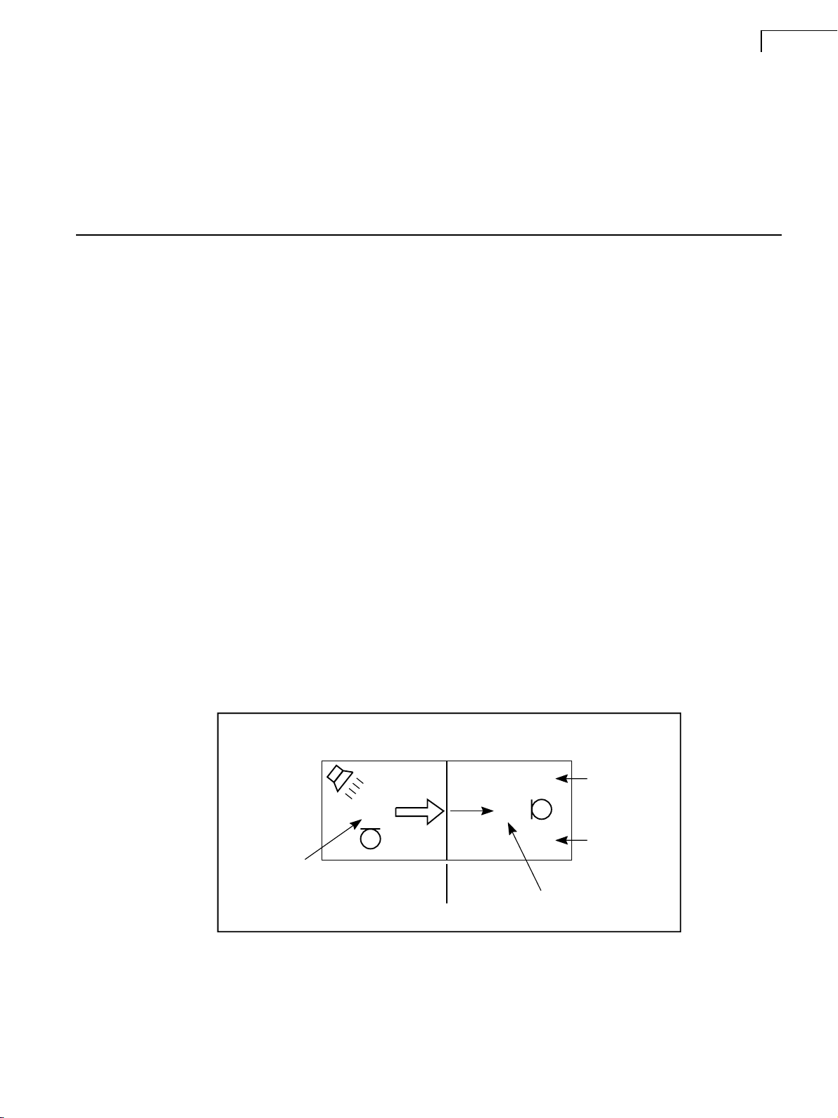
Measuring Sound Insulation ...................................................................................................................... 1
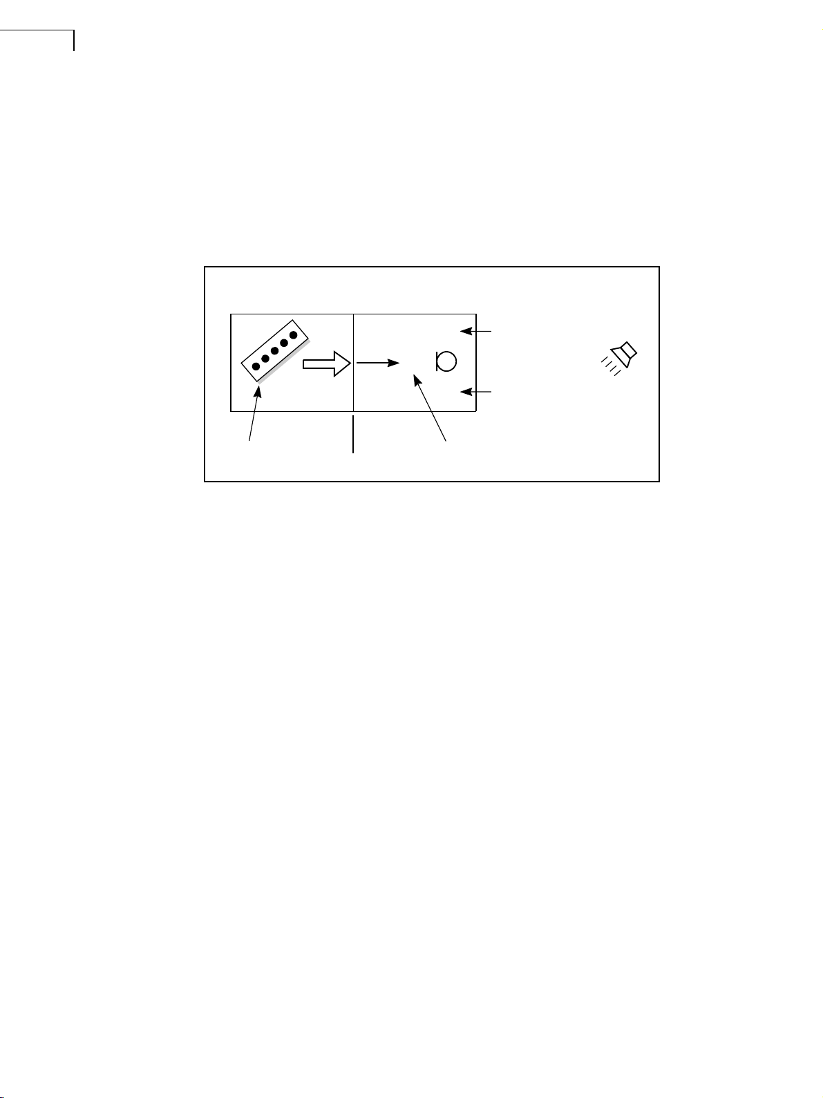
Measuring Impact Sound Insulation .......................................................................................................... 2
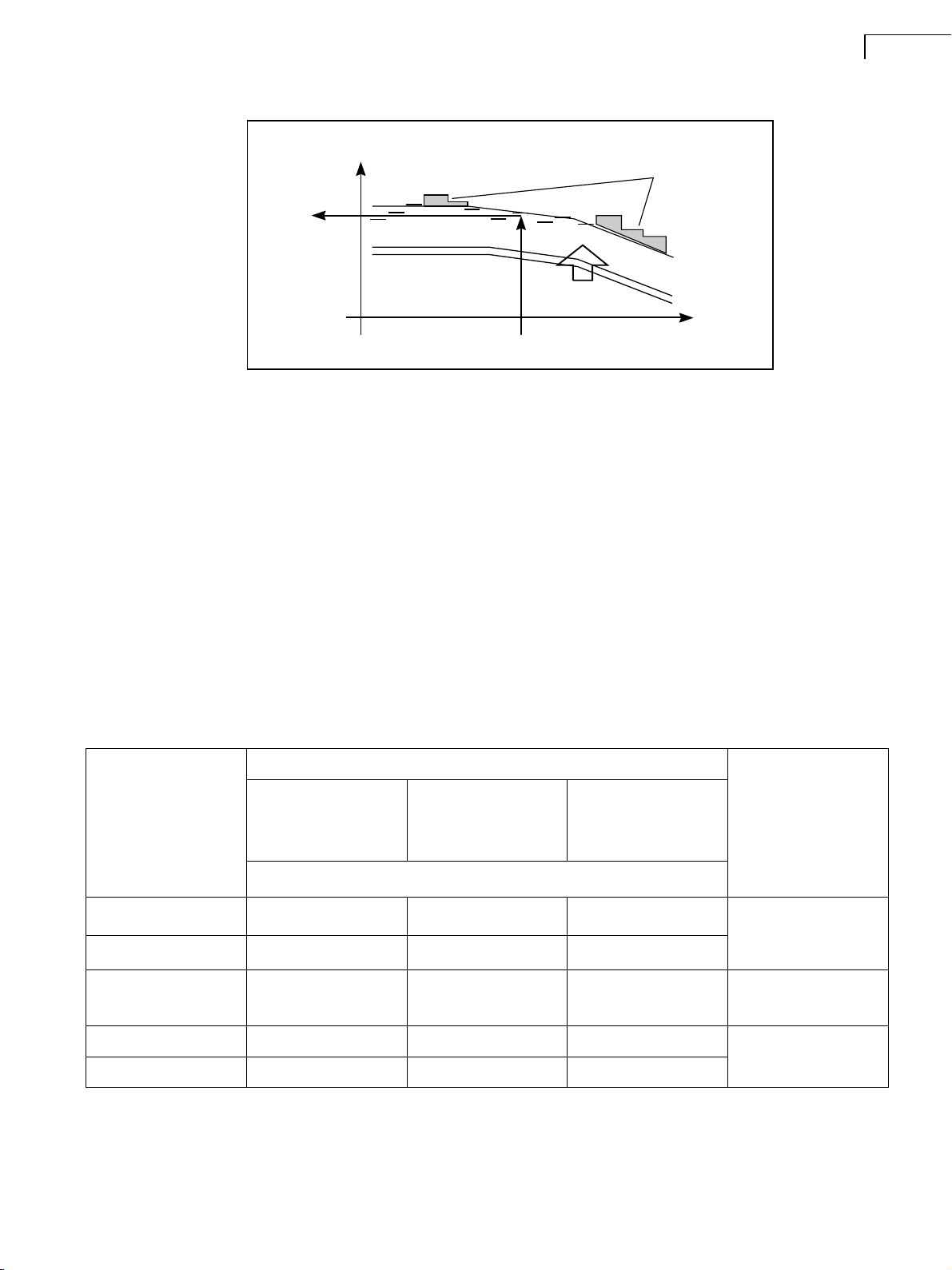
Weighting................................................................................................................................................... 2
1.3 How Much is Too Much? ........................................................................................................................... 3
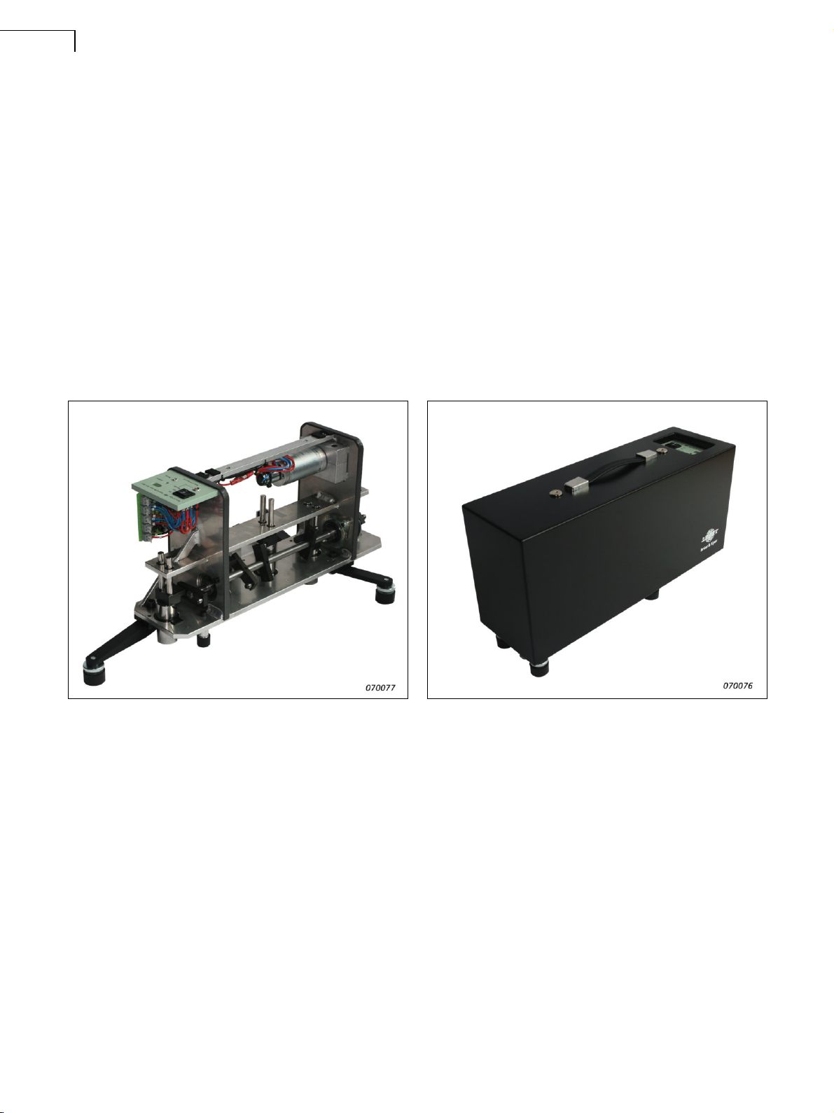
1.4 Construction of Tapping Machine Type 3207............................................................................................ 4
CHAPTER 2
A Complete Measurement System..................................................................................................... 5
2.1 A Complete Measurement System for Architectural and Building Acoustics ............................................ 5
2.2 Use of 2260-D/BZ-7204............................................................................................................................. 6
Measurement............................................................................................................................................. 6
Data Bookkeeping ..................................................................................................................................... 6
Positions and Average............................................................................................................................... 7
Reuse of Information ................................................................................................................................. 8
Built-in Generator ...................................................................................................................................... 8
Calculations ............................................................................................................................................... 8
Printing ...................................................................................................................................................... 9
Data Transfer to a PC................................................................................................................................ 9
2.3 Assessment and Reporting ....................................................................................................................... 9
Qualifier Type 7830 ................................................................................................................................... 9
Data Transfer............................................................................................................................................. 9
Qualifier Calculations................................................................................................................................. 9
Flexible Reverberation Averaging ........................................................................................................... 10
Documentation ........................................................................................................................................ 10
Building Acoustics Standards and Measured Parameters ...................................................................... 10
CHAPTER 3
User Guide for the Tapping Machine ............................................................................................... 13
3.1 Before Use............................................................................................................................................... 13
3.2 Initial Start-up .......................................................................................................................................... 15
3.3 Measuring................................................................................................................................................ 16
3.4 After Measuring ....................................................................................................................................... 16
3.5 Hints and Tips.......................................................................................................................................... 17
CHAPTER 4
Options and Accessories.................................................................................................................. 19
4.1 Remote Control Operation....................................................................................................................... 19
General.................................................................................................................................................... 19
Wireless Remote Control Kit UA-1476 .................................................................................................... 19
Using Remote Control Kit UA-1476......................................................................................................... 20
Remote Operation via Cable AQ-0633.................................................................................................... 21
Remote Control using Third Party Remote Control Systems .................................................................. 22
4.2 Battery Option.......................................................................................................................................... 23
General.................................................................................................................................................... 23
Installing Battery Kit UA-1477.................................................................................................................. 23
Battery Operation .................................................................................................................................... 25

CHAPTER 5
Routine Maintenance......................................................................................................................... 27
5.1 General.................................................................................................................................................... 27
5.2 Tapping Machine Equipped with Battery ................................................................................................. 28
5.3 Adjustment............................................................................................................................................... 28
Charging Regulator on the Battery Option .............................................................................................. 29
Hints and Tips about Maintenance and Adjustment ................................................................................ 29
Safety Tips............................................................................................................................................... 30
CHAPTER 6
Service and Guarantee...................................................................................................................... 31
APPENDIX A
Type 3207 Specifications .................................................................................................................. 33
A.1 Compliance with Regulations and Environmental Standards.................................................................. 33
A.2 Specifications .......................................................................................................................................... 34

1
Chapter 1
Introduction
1.1 About this Manual
This chapter describes procedures for measuring building acoustic properties such as airborne and
impact noise insulation. Chapter 2 covers Brüel & Kjær solutions for building acoustic measurements.
The rest of the manual covers the operation and maintenance of Tapping Machine Type 3207 and its
specifications.
1.2 Introduction
1.2.1 Measuring Sound Insulation
In Building Acoustics, the sound quality of buildings is planned and evaluated with the aim of improv-
ing the quality of life of the building’s occupants. For dwellings, good sound quality means that noise
from the normal activities of daily living does not disturb others. The noise may be airborne in origin
(from speech, music, household appliances, etc.) or stem from impact to the building structure (for
example, footsteps).
To measure sound insulation, a standardised sound source is used to simulate the potentially annoying
noise, and the resulting sound level is measured inside the apartment in question.
For airborne sound, a loudspeaker sound source is used, and the level is measured on both sides of the
partition (Fig.1.1). The level difference is then calculated and compared to building regulations.
Fig.1.1
Measurement of
airborne sound
insulation – setup
and parameters
The level difference must be corrected for the absorption in the receiving room and for the possible
influence of background noise. Hence, reverberation time and background noise level are also measured.
The parameters are measured not just at one position of source and receiver, but at a number of
positions in order to improve the measurement accuracy.
Source Room
Room 1
Receiving Room
Room 2
Receiving Room
Level
Partition
L1 L2
B2
T2
Source Room
Level
980427e
Background
Noise Level
Reverberation
Time

Tapping Machine Type 3207 – User Manual2
1.2.2 Measuring Impact Sound Insulation
For impact sound insulation, a different sound source has to be used, but otherwise the procedure is
similar to that for airborne sound.
A standardised impact sound generator (tapping machine) is used. This consists of hammers of stand-
ardised weight that drop from a standardised height at a standardised repetition rate. The vibration from
the tapping machine is transmitted through the building structure into the air in the receiving room.
This sound level (L2) is measured, and compared to building regulations after correction for reverbera-
tion time (T2) and possible influence of background noise (B2) (see Fig.1.2).
Fig.1.2
Measurement of
impact sound
insulation – setup
and parameters
Levels and reverberation time are all measured as spectra in 1/3-octaves (or 1/1-octaves), and the
background noise correction (if needed) is made according to the following equation:
L2c = 10 log (10L2/10 – 10B2/10)
The correction for absorption in the receiving room is made as follows:
LnT = L2 – 10 log (T/T0)(T
0= 0.5 s)
LnT is called the Standardised Impact Sound Pressure Level in which T is the measured T2. The
correction refers to an average reverberation time for dwellings of 0.5 seconds.
For field measurements, the result may be indicated as L´nT and ‘Apparent’ added to the name of the
result. In field measurements, transmission of sound may occur through flanking paths, as opposed to
laboratory measurements where flanking is carefully prevented.
Besides LnT, the Normalised Impact Sound Pressure Level is also used, calculated according to:
Ln = L2 + 10 log (0.016 V/T)
Again, L´n and the addition of ‘Apparent’ to the name may be used to indicate field measurements.
1.2.3 Weighting
Building regulations specify limits not in terms of spectra, but as single-number quantities calculated
from the L´nT or L´nw spectra. The calculating procedure is called weighting, illustrated for LnTw in
Fig.1.3. The result is called the Weighted Standardised Impact Sound Pressure Level.
Source Room
Room 1
Receiving Room
Room 2
Receiving Room
Level
Used only for T2
Partition
L2
B2
T2
Tapping
Machine
980428e
Background
Noise Level
Reverberation
Time

CHAPTER 1
Introduction 3
Fig.1.3
Single-number
result (LnTw) is
calculated by
shifting the
reference curve
upwards in 1 dB
steps until the
measured spectrum
exceeds the
reference curve by
less than (but as
close as possible
to) a sum of 32 dB.
The weighted result
is the value of the
reference curve at
500 Hz
For Ln, the weighting procedure is similar, resulting in the Weighted Normalised Impact Sound
Pressure Level.
For an overview of building acoustic standards and calculations, please refer to the Brüel & Kjær
Technical Documentation for Building Acoustic System, Literature No. BB 1078 (English).
1.3 How Much is Too Much?
How a person perceives a given impact noise from a neighbour depends not only on the neighbour’s
kind of activity and the impact sound insulation, but also on the use of the receiving room. However,
for people in normal dwellings, Table 1.1 gives guidelines for the perception of impact noise as a
function of impact sound insulation.
In many countries, present building regulations operate with a limit of around 53 dB. Considering that
many older buildings (and quite a few new ones) do not even fulfil this requirement, the need for
improvement (and measurements) is obvious.
500 Hz
Hz
Area < 32 dB
dB
LnTw
LnT
980429e
Table 1.1 Perception of impact noise in dwellings as a function of impact sound insulation L´nTw (adapted from
PWI: Schallschutz im Hochbau, Maienfeld, 1997)
L´nTw (dB)
Noise Generated in Adjoining Room
Normal
Walking with normal
footwear or house
footwear
Elevated
Running children or
walking barefoot
Extreme
Moving furniture and
boisterous children
Perception of Resulting Noise
63 Audible – intrusive Very intrusive Unbearable !
58 Audible Intrusive Very intrusive
53 Barely audible Audible Intrusive "
48 Inaudible Barely audible Intrusive ☺
43 Inaudible Inaudible Audible

Tapping Machine Type 3207 – User Manual4
1.4 Construction of Tapping Machine Type 3207
Tapping Machine Type 3207 is a standard tapping noise generator. It can be used for tapping noise
measurements to national and international standards. The unit is available with an optional mobile
power source (battery pack) and a wireless remote control.
The tapping machine uses five hammers each weighing 500 g that operate at 2 Hz dropping from a
height of 40 mm. This fulfils national and international standards. The hammers are operated via cams
on a single shaft. The shaft is driven by a DC motor via a toothed belt and gearbox.
The unit is based on a welded aluminium chassis. Weight and size have been kept to a minimum to
ensure ease of transportation. Three extendable legs with rubber feet support the unit during operation.
The rubber feet are height adjustable using the included gauges. This guarantees stable mounting.
The unit is powered via the supplied AC/DC adaptor, or the optional battery pack. The unit can be
remotely switched on and off with a cable or wireless remote control option.
Fig.1.4 Tapping Machine Type 3207 shown with and without housing. The picture on the left shows the tapping
machine with support legs extended

5
Chapter 2
A Complete Measurement System
2.1 A Complete Measurement System for Architectural and Building
Acoustics
The combined features of Investigator™ Type 2260-D and Qualifier Type 7830 PC Software provide
ideal tools for architectural and building acoustic measurements. This combination of well-proven,
reliable hardware and tailor-made software effectively avoids the necessity of a PC in the field. In
addition, the calculation of sound insulation curves and indexes can be done on the spot.
Fig.2.1
2260-D Investigator
with Tapping
Machine Type 3207
The following additional components complete the system:
• OmniPower Sound SourceTM Type 4296
• Power Amplifier Type 2716
• Flight Case KE-0348
A typical configuration for the system is shown in Fig.2.2.

Tapping Machine Type 3207 – User Manual6
Fig.2.2 The basic measuring system with Tapping Machine Type 3207
Investigator 2260-D
This is the standard Investigator loaded with the supplied BZ-7204 software. The use of this software
is described here for a typical application.
2.2 Use of 2260-D/BZ-7204
The main purposes of Type 2260-D and the BZ-7204 software are to measure the building acoustics
parameters, and to make sound insulation calculations.
2.2.1 Measurement
Calculation of airborne sound insulation normally requires measurement of:
• L1: Source room level
• L2: Receiving room level
• B2: Background noise in receiving room
• T2: Reverberation time in the receiving room
Depending on standard and calculation formula, it may not be necessary to measure B2 and/or T2.
Also, L1 measurements are not used in impact sound insulation.
BZ-7204 allows measurement of all these parameters in any order required.
In level measurements (L1, L2 and B2), it is the Leq value that is recorded. The measurement time can
be specified in steps of 1 second.
In reverberation time measurements (T2), a short-time Leq (down to 8ms) is used to record a multi-
spectrum for calculating reverberation time.
2.2.2 Data Bookkeeping
BZ-7204 has an automatic data bookkeeping system, that saves the user the task of remembering file
names, etc.
It is a hierarchical system with a “Job” record at the top level. A Job is denoted by a four digit number.
As an example, this could relate to a certain measurement location.a
Measurements for several partitions (denoted by a letter, A to Z), for example, walls and floors, can be
contained in one job.
Brüel&Kjær Type2260
0
?
dB
KE-0358 Flight Case
2716 Power Amplifier
3207 TappingMachine
2260-D
(with BZ-7204)
AO-0523 Cable (10m)
AO-1442
Interface Cable
PC
7830 Qualifier
4292 OmniPower
960479/
6
AQ-0667
BridgingCable
AQ-0673
Cable (10m)
a. Within a Job, one Task is performed, for example, Airborne Sound Insulation, Impact Sound Insulation or Reverberation Time.

CHAPTER 2
A Complete Measurement System 7
Each partition has a set of (L1), L2, B2 and T2 that consist of one or more positions of each. For each
partition the sound insulation can be calculated on the basis of the average of all positions of (L1), L2,
B2 and T2.
Four measurement displays are available in airborne sound insulation: L1, L2, B2 and T2. A clear
indication of which one has been selected is shown on the screen of Type 2260-D. It is easy to change
between them by pressing a softkey.
2.2.3 Positions and Average
It is possible to measure and store up to 25 positions each for L1, L2, B2 and T2. The positions are
measured one at a time and the spectrum can be viewed continuously on the screen.
Positions can be stored automatically with automatically incremented position numbers. Alternatively,
positions can be stored manually in any position number.
When the first position is stored (either manually or automatically) some setup parameters, for example,
the bandwidth, are “frozen” to make sure that all the positions for the job will be compatible.
Every time a new position is stored, the average is calculated.
In level measurements (L1, L2 and B2), it is possible to view the following displays:
– Instantaneous level
– Current position
– Single positions
– Average of all positions
These are shown as spectra. When looking at L2, the B2-curve may also be shown (and vice versa) to
indicate the distance to the background noise (see Fig.2.3).
Fig.2.3
Measurement of L2
and B2
Reverberation time measurements are made with the Interrupted Noise method. Ensemble averaging is
used on multiple decays in the same position to produce one average decay curve for each position.
Averaging of reverberation times (T20 and T30) is used across positions (see Fig.2.4) to provide fast
averaging results.
Fig.2.4
Spectrum of
Reverberation
Times

Tapping Machine Type 3207 – User Manual8
To check the quality of decays, it is possible, for each position, to look at the decay in each frequency
band (see Fig.2.5).
Fig.2.5
Decay at 500 Hz for
a typical
measurement
2.2.4 Reuse of Information
To save measurement time, L1, B2 and T2 may be copied from another measurement. This is relevant
when several partitions have common source- or receiving room.
2.2.5 Built-in Generator
The built-in generator can supply pink or white noise in the bandwidth used for the measurement. The
signal is switched on and off automatically in accordance with the performed measurement. The noise
signal may be connected to a power amplifier and loudspeaker. Alternatively, an on/off output signal
can be selected, to control an external generator.
2.2.6 Calculations
As soon as just one position of L1, L2, (B2) and T2 has been measured, the sound reduction index
(spectrum and weighted) can be calculated (see Fig.2.6 and Fig.2.7).
Fig.2.6
Calculation of the
Airborne Noise
Sound Insulation
according to ISO
standards
Fig.2.7
Calculation of the
Impact Noise Sound
Insulation according
to ISO standards

CHAPTER 2
A Complete Measurement System 9
Generally the sound insulation is calculated (for each partition) from the average of all the positions of
L1, L2, B2 and T2. It is possible to exclude positions from the average to see what effect certain
positions have on the result.
Several calculation formulae can be selected, depending on the selected standard.
The following standards can be selected: ISO, DIN, BS, SS, ÖNORM, Sia, UNI, NF, UNE, NEN and
ASTM. For standards and parameters see Table 2.1 and Table 2.2.
2.2.7 Printing
Printing is possible in several formats for on-the-spot documentation. Plus, all screen pictures can be
sent to a printer from the 2260D.
The type of print-out depends on the current display: Spectrum, Overview, Result or Setup.
The scope of printed data may be selected as one Partition, or the entire Job.
2.2.8 Data Transfer to a PC
Measurement data can be transferred to a PC for post-processing using Qualifier Type 7830 software.
Furthermore, data can be transferred in formats suitable for processing in a spreadsheet.
2.3 Assessment and Reporting
2.3.1 Qualifier Type 7830
Qualifier Type 7830 PC-software provides the perfect solution for post-processing and documentation
of measurement results.
2.3.2 Data Transfer
On-the-spot or back in the office, data can be transferred to a PC from Type 2260-D.
Transfer from Type 2260-D is either direct, via its RS–232 serial interface, or indirect, via PC-cards.
An Interface Cable AO-1442 is available for data output to a PC via the serial interface.
Data are transferred maintaining the job and partition groupings that were made with Type 2260D.
2.3.3 Qualifier Calculations
Qualifier Type 7830 works with the same book-keeping system as Type 2260-D. This means that when
data has been transferred to the PC you see the same results as in Type 2260-D, including selected
standard, excluded positions and other set-up parameters.
Qualifier Type 7830 fulfils the same standards as listed for BZ-7204. See Table 2.1 and Table 2.2.
With Qualifier Type 7830, it is possible to display the reverberation measurements as 3D-Multispectra.
This provides a complete overview of the frequency dependent reverberation curves (Fig.2.8).

Tapping Machine Type 3207 – User Manual10
Fig.2.8
3D Multispectra,
showing
reverberation decay
curves displayed in
Qualifier
Using Qualifier’s spreadsheet-like datasheets, it is also possible to manually adjust data used in calcula-
tions, for example, to change levels or reverberation times. The result can be observed immediately.
Reverberation times can be modified by drawing a new slope line with the mouse across a displayed
decay curve.
For diagnostic purposes, the reduction curve can be modified and the single value will adjust according-
ly. And because manual input of data is possible, modifications for walls and rooms can be simulated.
2.3.4 Flexible Reverberation Averaging
Reverberation-time measurements may be averaged in two ways:
• Averaging of reverberation times (T20 and T30)
• Averaging of decay curves (multispectra), also called ensemble averaging. This mode has the advan-
tage of producing an average decay curve (multispectrum) for each frequency band
2.3.5 Documentation
Extensive documentation facilities are available. These allow items such as graphs and text to be
entered into a report and printed. Graphs can also be exported via the clip-board.
2.3.6 Building Acoustics Standards and Measured Parameters
Table 2.1 and Table 2.2 give an overview of the standards supported by BZ-7204 and the parameters
calculated by the software.
Table 2.1 Building Acoustics Standards
Sweden Germany Austria UK Switz. Italy France Spain Holland USA
Measurement ISO SS DIN ÖNORM BS SIA UNI NF-S31 UNE NEN ASTM
Typical
Parameters
R´
L´n
R´
L´n
R
L´n
DnT
L´nT
DnT
L´nT
DnT
L´nT
Dn
Ln
DnAT
LnAT
DnAT
LnAT
llu
lco
FTL
Ln
Airborne
Lab 140-3 EN20140-3 20140-3 S5101 20140-3 8270-1 -051 74-040-84/3
Field 140-4 EN20140-4 52210-1 S5100-1 2750-4 181 8270-4 -054, -057 74-040-84/4 5077 E336-90
Impact
Lab 140-6 EN20140-6 52210-1 S5101 2750-6 8270-6 052 74-040-84/6
Field 140-7 EN20140-7 52210-1 S5100-2 2750-7 181 8270-4 -056, -057 74-040-84/7 5077 E1007-90
RT 3382
354 52212 5077
Rating
Air 717-1 ISO717-1 52210-4 S5100-1 5821-1,-3 181 8270-7 -057 NBECA-88 5077 E413-73
Impact 717-2 ISO717-2 52210-4 S5100-2 5821-2 181 8270-7 -057 NBECA-88 5077 E989

CHAPTER 2
A Complete Measurement System 11
Table 2.2 Calculated Parameters
Standard ISO SS DIN ÖNORM BS SIA UNI NF UNE NEN ASTM None
Country Sweden Germany Austria UK Switz. Italy France Spain Holland USA
Basic
Standard
ISO140
ISO717
ISO140
ISO717
ISO140
ISO717
ISO140
ISO717
ISO140
ISO717
ISO140
ISO717
ISO140
ISO717
NF
S31-05x ISO140 ISO140
ASTM
E336,
1007
ISO140
Airborne
Calculated
parameters
D Dw Dn
Dnw
DnT
DnTw
R´ R´w
R Rw
DnTw+C
DnTw+Ctr
R´w or Rw
+
C Ctr
C
50-5000
C
100-5000
Ctr
50-5000
Ctr
100-5000
ISO plus
R´w8
Rw8
Dw8
DnTw8
see ISO See ISO See ISO
ISO
but:
DnTw+C
–Cv
See ISO
D
DnT
DnATrose
DnATroute
R
Rrose
Rroute
ISO plus
DnAT
RA
DnT
Ilu
Ilu;k
Gi
G
A
G
A;k
NR
NIC
NNR
NNIC
FTL
FSTC
D
Dn
DnT
R´
R
Impact
Calculated
parameters
L´nt
L´nTw
L´n L´nw
Ln Lnw
L´nw, Lnw
or L´nTw
+
Ci
Ci
50-2500
ISO plus
L´nw8
Lnw8
L´nTw8
See ISO See ISO See ISO ISO See ISO
LnT
Ln
LnAT
LnA
ISO plus
LnAT
LnA
LnT
Ico
Ln
IIC
L´nT
LnT
Ln

13
Chapter 3
User Guide for the Tapping Machine
3.1 Before Use
Fig.3.1
The tapping
machine with
housing on and
support legs folded
away in carrying
position
Remove the housing (1) by removing the two screws (2) with the added hexagon wrench (Fig.5.1).
The hammers (4) are fixed with cable ties (3) to the upper guide plate (5) to enable safe transportation.
These cable ties need to be cut and removed. If you are sending the machine back to Brüel & Kjær for
service, please fix the hammers again with cable ties, string, etc., to prevent damage during shipment.
1
2

Tapping Machine Type 3207 – User Manual14
Fig.3.2
Safety ties for
transportation
If the battery option is installed, the battery (6) must have its negative terminal reconnected. Do this by
plugging the blue cable labelled −B to the negative terminal (7).
Fig.3.3
Connection of the
Battery
The tapping machine is now ready to use. You can now replace the housing.
Note: The fixing screws should not be over-tightened.
3
4
5
48
6
7
Table of contents
Popular Industrial Equipment manuals by other brands

SPX
SPX Power Team HNS150A Parts List, Assembly, and Operating Instructions

Eaton
Eaton Airflex CB Installation & operation

Vega
Vega PLICSMOBILE Series operating instructions

NetterVibration
NetterVibration NWE Series operating instructions

Rottler
Rottler SG8 Operation and maintenance manual

Siemens
Siemens SIMATIC NET RUGGEDCOM RX5000 Equipment manual