BRUEL & KJAER 4148 User guide

1/2" Condenser Microphone
Type 4148
A precision condenser microphone
needing
only
28
V polarization.
Frequency range
4Hz
to
16
kHz.
Sensitivity 12.5 mV
per
N/m2•


Instructions and Applications
Half-inch Condenser Microphone Type 4148
Precision Condenser·Microphone
for
measurement purposes in conjunction
with
a Sound Level Meter
or
Preamplifier .2619. Features
low
polarization
voltage.
March 1970


Contents
1o
Introduction o o o 0 o o 0 0 0 o 0 0 0 o o 0 0 0 0 0 0 0 0 0 0 0 0 0 0 0 o o o o o o o o 0 0 0 0 0 5
Purpose
of
the half-inch condenser microphone . . . . . . . . . . . . . . . . 5
Principle
of
condenser-Microphone . . . . . . . . . . . . . . . . . . . . . . . . . 5
Definitions..
. . . . . . . . . . . . • . . . . . . . . . . . . . . . . . . . . . . . . . . • . . . 7
2o
Description
..
o o o
•••••••••
o o • o o • o o • o
••••
o • o o • o o • o o o
••••
0 .
11
General
..........
0
•••••
o
•••••••••
o
•••••
o
••••••
o
•••
o o
o.
11
Description
of
the Cartridge Type 4148 . o • • • • • • • • • • • • • • • • • • • •
11
3o
Characteristics • o o
••
o o • o • • • o o • o o o o o o o o o o o o o • • o o • o
•••
o o o 0
14
Sensitivity, Frequency
Response
.....................•••...
14
Free-field corrections . . . . . . . . . . . . . . . . . . . . . . . . . . . . . . . . . . . . 17
Directional characteristics . . . . . . . . . . . . . . . . . . . . . . . . . . . . . . . . 19
Dynamic
Range,
Noise
and
Distortion
.....................•.
20
Equivalent Volume
.................................•....
20
Polarized cartridge capacity . . . . . . . . . . . . . . . . . . . . . . . . . • . . . . . 20
Long-term stability
......•...........
0 0
••••••••••••••••••
21
4.
Environmental influences o o o • o
•••••
o • o
•••
o
••••
o
••
0 o
•••
o o • •
23
Influence
of
temperature . . . . . . . . . . . . . . . . . . . . . . . . . . . . • . . . .
23
Influence
of
ambient
pressure
. . . . . . . . . . . . . . . . . . . . . . . . • • . . . 24
Influence
of
humidity
...................................
24
Influence
of
vibration • . . . . . . . . . . . . . . . . . . . . . . . . . . . . . . • . . . . 25
5. Operation
••
o
•••
o o
••••
o
••
o • o
••••
o
••••••••••
o o
••••
o • • • • •
26
Mounting
............................•
0
•••••••••••••••
26
Operation
with
the 2619 preamplifier o
••••••••••••••••••••••
26
Operation
with
Cathode followers 2614
and
2615 . • . . . . . •• • . . . • 27
Operation
with
Sound Level Meter 2206 (2205 +
UA
0208)
•..••••
27

6. Service and Maintenance • • • . • . . . • • . . . . •. . • . . . . . . • . . • •. . . . 28
7. Microphone Calibration
••.•••••••.••••..........•....••••
29
Pistonphone Type 4220 . . . . . . . . . . . . . . . . . . . . . . . . . . . . . . . . . . 29
Sound Level Calibrator Type 4230
..........................
·29
Microphone Calibration Apparatus Type 4142
.................
30
Electrostatic Actuator
UA
0033
............................
31
8.
Accessories . . . • . . . . . . . . . . . . . . . . . . • . . . . . . . . . . . . . . . . . . . . . 33
9.
Spec;ifications . . . • • • • • • • • . . •
..
• . . . • • • • • . . . . . . . . . . . . . . . . . . 39

1.
Introduction
1.1. Purpose
of
the half-inch Condenser Microphone
There
are
many
different
types
of
microphoneand signal conditioners
used
to
measure sound pressure levels. In the
majority
of
cases,
the
condenser micro-
phone
is
the
type
to
be
preferred, since
it
features high
stability
and
flat
frequency characteristics combined
with
reasonably high sensitivity. Itssmall
size minimizes the disturbance
of
the sound field due
to
the
presence
of
the
microphone.
The condenser microphone
type
4148
is
designed
for
precision sound pressure
measurements
wi
th the Precision Sound Level meter 2206 and
needs
only
a
low
polarizationvoltage
of
28 V instead
of
the
norrnal200
V.
Despite
the
low
polarization voltage, a sensitivity about 12.5
mV
per Nfm2
(-38 dB ± 2 dB
re
1 V per
Nfm2)
is
obtained, which
is
comparable
with
that
of
similarly sized microphones needing higher polarization voltages.
Without
seriously affecting
the
frequency response, the sensitivity
can
be
varied
from
12.5
mV
per N/m2
to
60
mV
per Nfm2 simply
by
varying the
polarization voltage between
28
and 120 V DC. The microphone
has
a
flat
frequency response between 4 Hz and
16kHz
and a wide dynamic range. Its
most outstanding feature
is
excellent long-term
stability
under a great range
of
environment
al
conditions.
An
excellent battery driven precision sound measuring system
is
obtained in
conjunction
wi
th a precision sound level meter Type 2206
or
a sound level
meter Type 2205 plus adaptor
UA
0208
or
with
F.E.T.- preamplifier Type
2619 and a measuring voltmeter.
An
extensive
range
of
accessories provides great measuring versatility.
1.2. Principle
of
Condenser Microphone
A capacitive transducer converts energy
from
mechanical
to
electrical form,
or
vice
versa.
The conversion
is
effected
by
mechanically inducing changes in
electrical capacitance between
two
conducting plates separated
by
an
insula-
tor
and detecting the capacitance changes electrically. The condenser micro-
phone
is
a transducer operating on this principle.
It
consists basically
of
a
thin
metal diaphragm mounted in close
proximity
to
a rigid back plate
forming
a capacitor
with
air
as
insulator between the conductors. A
DC
voltage, the so-called polarization voltage, charges the system.
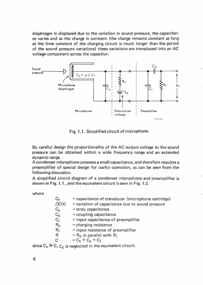
When
the
5

diaphragm
is
displaced due
to
the variation in sound pressure, the capacitan-
ce
varies and
as
the
charge
is
constant (the charge remains constant
as
long
as
the
time
constant
of
the charging
circuit
is
much longer than the period
of
the sound pressure variations) these variations are transduced
into
an
AC
voltage component across
the
capacitor.
Sound I\.
pressur_e
___
____,V
Ct+
6C(t)
(~======1
Microphone
diaphragm
Microphone
I
I
I
I
I
Cs:
Polari
zation
1
voltage
Preamplifier
17oo5~
Fig. 1.1. Simplified
circuit
of
microphone.
By careful design
the
proportionality
of
the AC
output
voltage
to
the sound
pressure can
be
obtained
within
a wide frequency range and
an
extended
dynamicrange.
A condenser microphone
posesses
asmall capacitance, and therefore requires a
preamplifier
of
special design
for
useful operation,
as
can
be
seen
from
the
following
discussion.
A simplified
circuit
diagram
of
a condenser microphone and preamplifier
is
shown in Fig. 1.1., and the equivalent
circuit
is
seen
in Fig. 1.2.
where Ct =capacitance
of
transducer (microphone cartridge)
.6.C(t)
=variation
of
capacitance due
to
sound pressure
Cs
= stray capacitance
Cc
=coupling
capacitance
Ci
=input
capacitance
of
preamplifier
Rc
=charging resistance
Ri
=input
resistance
of
preamplifier
R =
Rc
in parallel
with
Ri
C =
Ct
+Cs
+Ci
since
Cc
~C,
Cc
is
neglected in the equivalent circuit.
6

From Fig.1.2.
it
can
be
seen
that
the
output
voltage V0
is
6C(t)Eo
Ct
Vo
=
~c
(t)
C
Eo
j w R C
1+jwRC
R
17oo7'J
Fig. 1.2. Microphoneequivalentcircuit.
It
can
be
seen
from
the equation
that
the sensitivity
is
proportional
to
the
polarization voltage
but
inversely proportional
to
the
total
capacitance'
C.
Any
capacitance additional
to
the transducer capacitance
e.g.
thecapacitance
of
a preamplifier,
would
load the transducer and decrease
the
output
voltage
V0. This
means
that
the
total
capacitance in
circuit
should
not
exceed Ct
of
the
transducer more than absolutely necessary. Hence
the
need
for
integral
construction
of
thecartridge and preamplifier (impedance converter).
1.3. Definition
of
Free-field,
Pressure
and Diffuse Field
Response
The sensitivity
of
a transducer
for
different
frequencies
is
normallyexpressed
as
the
ratio
of
its electrical
output
to
its mechanical
input
and
is,
ingeneral, a
function
of
frequency,being constant in a broad frequency
range.
When the
sound pressure
is
uniformly
applied over
the
surface
of
the diaphragm,
the
ratio
of
the
RMS
output
voltage,
e,
to
the
RMS
sound pressure, P1,
is
called
the Pressure Response, Mp,
of
a microphone at a given single frequency and
written
7

Relating
to
a reference response, Mr which equals
(1
-:-:r:¥-or
1
Vm
2
puar
N
apressure response level
can
be
defined
as:
or
1 Vcm2
dyne
20 log10
~
(dB)
Mr
The so-called Free-field Response
Mt,
is
defined
as
the ratio
of
the
RMS
output
voltage,
e,
to
the RMS sound pressure, P
0, existing in the sound field
before the microphone
is
placed in position, i.e.
e
Mf
=-
atagiven single frequency.
The diffuse-field response level relative
to
reference response, Mr,
can
be
defined
as:
Mf
Rf
=
2Q-Iog1
o
Mr
(dB)
The definitions
of
Free field and
Pressure
Response are illustrated in Fig. 1.3.
Free-Field Response=
~o
Pressure
Response=
;,
vo~ts
_
f"J
~-M
i
-crop-hone~
CZ~~--~
Wavelength
Sound pr
essure
P
0
___
_
_______
_
0°
incidence
f6
2f
60
Fig. 1.3. Definitions
of
Free field and
Pressure
Response.
8

The
two
definitions
are
identical
for
a microphone having negligible dimen-
sions compared
to
the
sound wavelength.
If
the wavelength becomes compar-
able
to
the
front
of
the microphonethe transducer's
body
acts
as
areflector in;
the sound field and producesalocal change inthe resulting sound pressure
and.
causes
an
increase in pressure onthediaphragm which means
an
increase
of
the
output
voltage.
The reflection dependsonthe angle
of
incidence
of
the sound,
as
shown in Fig.
1.4.
90°Parallel to plane of diaphragm
Fig. 1.4.
Definition
of
angle
of
incidence.
In
the
case
of
the B & K half-inch microphone Type 4148, the free-field and
pressure responses begin
to
diverge
at
about
2000Hz,where the wavelength
is
10timesthe diameter
of
the microphone.
The free-field response
of
a microphone
is
of
interest when the transducer
is
operated in
an
open
space,
many wavelengths removed
from
a sound source
or
any reflecting boundaries. In closed cavities, couplers, and artificial
ears
the pressure response
is
important.
Furthermore, in some instancesthe pressure response
is
agood approx1mat1on
to
the
characteristics
of
the
transducer when sound
is
incident upon
it
from
random directions.
If
the sound energy density
is
uniform
and the
time
average
of
the
mean-square sound pressure
is
the
same
in all directions,this sound field
is
called adiffusefield.
The ratio
of
the
RMS
output
voltage,
e,
to
the
RMS
diffuse-field sound
pressure, Pd,
for
all angles
of
incidence
of
the sound wave
is
called
the
Diffuse-Field Response
at
a given single frequency and defined
as:
Md
=-L
Pd
9

The diffuse-field response level relative
to
reference response, Mr,
can be defined
as:
Rd =
20
log 10·
~~
(dB)
The sound
field
inveryreverberant roomscan
be
considered
as
adiffuse
sou
rid
field
•.
10

2. Description
2.1. General
A complete condenser microphone consists
of
a microphone cartridge
type
4148
and an impedanceconvertersuch as
the
preamplifier 2619.
Since for
free~field
measurements
the
microphone should be placed remote
from
the
measuring instruments a microphone stand and different types
of
extension cablesare available, see Accessories.
2.2. Description
of
the
Cartridge Type
4148
The microphone cartridge Type
4148
meets
USA
standard
XL
but has been
designed primarily for
the
B & K 2206 which requires 28 V polarization but'
can work with up
to
the
range
of
100
V.
This means
that
the
cartridge
is
a
precision measuring microphone,
but
may, of course, be used
as
a studio
microphone
as
well.
Oiaphra
Back
plate
Hole for
static
pressure
equalization
Fig.
2.-1.
Schematicconstruction ofa condenser microphone cartridge.
Furthermore,
the
microphone
is
mechanically and electrically stable and can
operate over a wide range
of
ambienttemperature, static pressure and humidi-
ty
conditions.
The schematic construction
of
the
condenser microphone cartridge
is
shown
in
Fig.2.1., and consists basically
of
a 2
)Jm
thick nickel diaphragm which
is
11

stretched over
the
edge
of
the
housing and
is
mounted
at
a distance
of
about
20
JJm
from
the
back plate. The back plate
is
made
of
high nickel alloy and
fixed
to
the
silicone treated quartz insulator, where
the
silicone increases
the
moisture resistivity. Good design, careful choice
of
materials, and a
complete artificial ageing process give excellent long term stability.
To ensure perfect electrical
contact
the
surface
of
the
output
terminal
is
gold
plated.
Thedimensions
of
the
microphonecartridge are given
in
Fig. 2.2.
Fig. 2.2.
4148
dimensions.
The holes
in
the
backplate control
the
damping
of
the
diaphragm resonance.
The damping
is
also controlled
by
adjusting
the
spacing between diaphragm
and backplate. The
4148
is
overdamped
in
order
to
obtain afree field response
which
is
as flat as possible. The holes
for
pressure equalization are situated
in
front
of
the
grid- and coupler-mounting thread and allow air
to
leakfrom
the
internal volume
to
outside
to
equalize changes
in
staticair pressure.
Therefore, pressure equalization
is
also obtained with closed cavity measure·
ments. The equalization rate determines
the
low-frequency acoustic cut-off,
and therefore
the
microphone's sensitivity
to
fluctuations
in
ambient pres·
sure.
12

The equalization
is
controlled by a
20
pm
wide slot
in
the
spacer ring
between
the
quartz insulator and housing. The slot resistance determines
the
acoustic cut-off
at
the
lower limiting frequency. The time constant
of
the
pressure equalization
is
around 0.1 sec.
13

3. Characteristics and Calibration Chart
The characteristics
of
the
4148,
e.g. sensitivity, frequency response, cartridge
capacity and summarized specifications as well as
the
conditionsofcalibration
test
are individually recorded for each cartridge. Atypical cartridge calibration
chart
is
shown
in
Fig. 3.1 .
---
.,__
__
~
T)ttoe4
1
..
.........
,(~,.~
.
..
-==..:=w:-,.-M;
.
--•v
~.~':;::r'O:.'.!O~~~~'t':~
..t.;.lt....
IIIV
J
-w::
.
.lUI..•rt
.
1
Vf
~
..
tldl
....•
vfw.,or.;
.
l!
,1
....
...
,v
jw_.
!:":~~.c!'TIII,..,._..._
c - ..l.f
,.f
...... ,
•)c...-,-
.....
cn-.ouftd_,...,,no
onl
..
llllll-~11>-lnY/NI
...
-
-»
..
o.u fw•.
:=i:;::=::.,"
...
~
-
I..V/-
-
-·-re.IY
/
~
.
.........
,......,....,._
:J
0 0 0 0 0 0 0 0 0 0 0 0 0 0 0 0 0 0 0 0 0 0 0 0 0 0 0 0 0 0 0 0 0 0 0 0 0 0
-==--
@((!*
~-:~~~cu~p=::..--
..
-1
T_
.........
.:t.t
...... •o
...._
_ _
?.f.f
...... -
...
~~
-
...
~1.
.....
..
DUo
••
f.:f.:U..... .......... ...
:~.,l·
......
- 1000 --
10000
Fig. 3.1. Typical cartridgecalibration chart.
-
,_A
ICI,.oo.
"'
3.1. Sensitivity, Frequency Response
The microphone cartridge has a nominal
open
circuit sensitivity
of
12~5
mV
per N/m2
or
-38 dB re 1V per N/m2 (i.e. 1.25 mV/)Jbar
=-58
dB
re
1V/]Jbar)
when used with a polarization voltage
of
28
V.
The
microphonecartridge may,
however, be
operated
with
any
polarization voltage
up
to
120
volts.
The
resultantchange
in
sensitivity can be seen
in
Fig. 3.2. The
output
voltage
of
the
transducer
is
approximately proportional
to
the
polarization voltage. Using
up
to
120
V polarization voltage
the
sensitivity can be increased
to
60
mVI per
N/m2• The frequency response for various polarization voltages
is
illustrated
in
Fig. 3.3.
The
4148
has a frequency response which
is
corrected for free-field measure-
ments,
so
that
it gives an
output
which represents
the
free-field sound pressure.
The normal incidence free-field response with protecting grid
is
constant
within
±2
dB from
4Hz
to
16 kHz with preamplifier
Type
2619,asshown in
the
top
curve
of
Fig. 3.1.
14

+15
+10
al
-o+5
c
!:"
0
-
~
-~-
5
Q)
V)
-10
~
~
~
~
--
~
,.,..,.
~
v
~
_/
v
,
10
20
30
40
50
60
70
80
90
100
110
120
Polarization
in Volts
Fig.3.2. Sensitivity as a function
of
polarization voltage.
The diaphragm of
the
microphone has a natural resonance
at
about
11
kHz,
which
is
controlled by
the
compliance and mass
of
the
diaphragm itself, and
the
inside volume
of
the
microphone. This resonance
is
damped very carefully,
by air friction
in
the
strictly controlled air gap between
the
diaphragm and
the
O
OOO
OO
O
OODOODOOO
O O
DDODODDDOODOOODOOOOOOOODOOOOOOO
......
__
_
-- -
.,.
__
'"'
"
--
~-"-"
-
--
·
·
LU..
F
"--
'-
---
w•.
~
--
-~
-
~F-.Iouolo~
·
-
0010
OP1123
10
SdB
Fig. 3.3. Frequency response
at
different polarizationvoltages.
15

back plate. Thus a frequency response which
is
flat
to
higher frequencies
than
the
resonance
is
obtained.
The low frequency response
is
determined either
by
the
acoustic cut-off
of
the
microphone,
or
by
the
electrical low frequency cut-off
of
the
preampli-
fier, whichever
is
the
greater. The acoustic cut-off
is
below
2.0
Hz
{-3
dB
point) and
is
determined by
the
pressure equalization hole.
The electrical low-frequency cut-off
{-3
dB)
is
determined by
the
preampli-
fier
input
resistance and
the
total capacitance
in
the
input
circuit,
as
can be
seen from
the
equation in Section 1.2.
Thisfrequency
is
where
and R
c
27T
RC
=input
resistance
of
preamplifier
= cartridge capacity +
input
capacitance
of
preamplifier
Typical values for
Rand
Cwhen
the
preamplifier
is
Type
2619
are:
giving
+3
co
""'0
0
c
=4GQ
= 18 pF
=3Hz
......
-
;~
~
....
::I
Q.
Acoustical
Response
_..
•
~~':····
.,..--
..
···
~
~
-;
-3
0
-6
0.5
/
,,
·•
~!--System
Response
""
.·
/
.··
~~--->--
1
EIL),;LI
1
Response
, •"""""''f-
~"".·····
,
.··
~
I Ill I
2 5
10
20
50
Frequency
in
Hz
-f'lDo
58
Fig.3.4. Upper Limit of Low Frequency Response
16

Note
that
R should be as large as possible for a good low frequency respon-
se, hence
the
use
of
field-effect transistors
in
the
2619
and
UA
0208. Large
input
C,
however, reduces
the
sensitivity and loads
the
transducer, although
the
low frequency response would benefit.
3.2. Free-Field Corrections
The pressure increase which
is
caused by
the
reflections
of
free-field sound
waves on
the
microphone diaphragm becomes appreciable above
2000
Hz.
The corresponding correction curves are shown
in
Fig.3.5. a and b.
By
adding
the
free-field correction
to
the
pressure response
the
frequency
response for
the
various angles of incidence
is
obtained.
(A
definition of
angle of incidence
is
shown
in
Fig.1.4.) The free-field corrections are
less
dependent on
the
angle
of
incidence if a Nose Cone
is
screwed
onto
the
microphone cartridge (see: Accessories).
10
Free field
corrections
for
type
414S /
-without
protecting
grid
--+-~+--+----~V-...,£.--l
dB
/
~--~--~-~-4--+-~~-~-----~~-~~
v/v
I
1soo\
§
'Cki
··-
•••!i!!i!!!i!!i!!~'i!!l'""'!li"lit~~~o•rncidence
-5
I I I I I I I I
2 3 4 5 6 7 8 9
10
kHz
15
20
Fig.3.5.a. Free Field Corrections when Pressure Characteristics
are Determined by Electrostatic Actuator Method.
(Without Protecting Grid).
17

The random incidence corrections, S, are calculated according
to
the
formula
given in
the
recommendation
of
the
I
EC
for
Sound
Level Meters (I
EC
23
Para. 8.2):
S2::;:
0.018
· S20 +
0.129
· S2
30
+
0.224
· S2
60
+
0.258
·
S2
90 +
0.224
·
S2120
+0.129
· S2150
+0.018
·S21ao
So, S3o, ....
S1so
=free field corrections
at
the
respective angles
of
incidence.
18
10
dB
5
0
-5
Free
field
corr~ctio~s
fo~
type
4148 /
with
protecting
grid
v/
/
o/'
/ v
i/
/Joo
/
fL_60°
v~
"
/V::/
I
,--~~~Q2~-~
--::::::::
.::;:::::.[..../
~--
Vi/'
/o
~
c:::::--
......
180°
1
.-Y~
·
~_;f:\
~~
I
--
-....
§C
I I
2 3 4
-
~.2d
0
~9(
-
,..._
~
--
......
~:--!--
/
1f'
'\
180"
150,
( I
J.}~O"incidence
'\
I I I I I I
5 6 7 B 9
10
kHz
15
20
Fig.3.5.b. Free Field Corrections when Pressure Characteristics
are Determined by Electrostatic
Actuator
Method.
(With Protecting Grid).
Table of contents
Other BRUEL & KJAER Microphone manuals

BRUEL & KJAER
BRUEL & KJAER 4964 Guide

BRUEL & KJAER
BRUEL & KJAER 4117 User guide

BRUEL & KJAER
BRUEL & KJAER 4184-A Guide

BRUEL & KJAER
BRUEL & KJAER 4111 User guide

BRUEL & KJAER
BRUEL & KJAER 4952 Quick start guide

BRUEL & KJAER
BRUEL & KJAER 4138 User guide

BRUEL & KJAER
BRUEL & KJAER 4188 User manual

BRUEL & KJAER
BRUEL & KJAER 5935 Guide