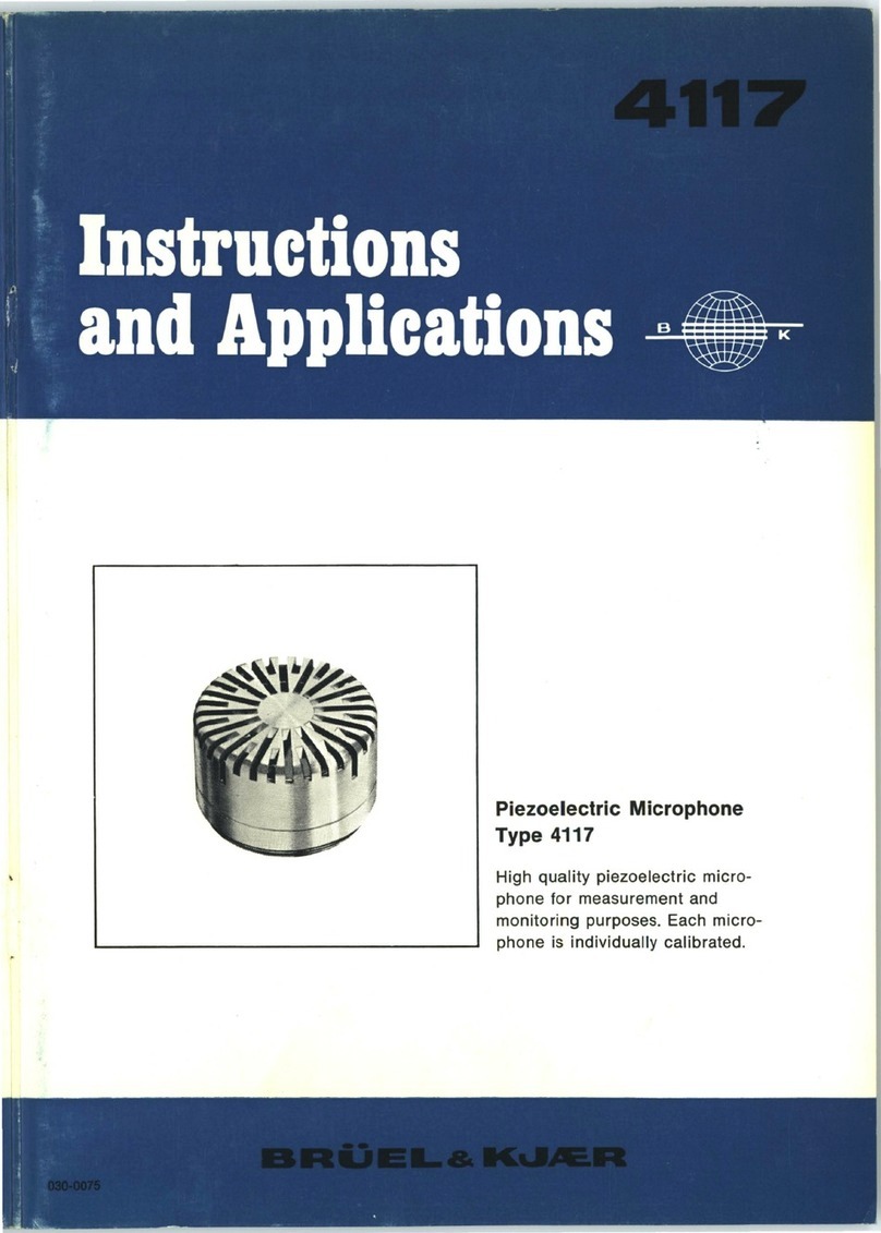
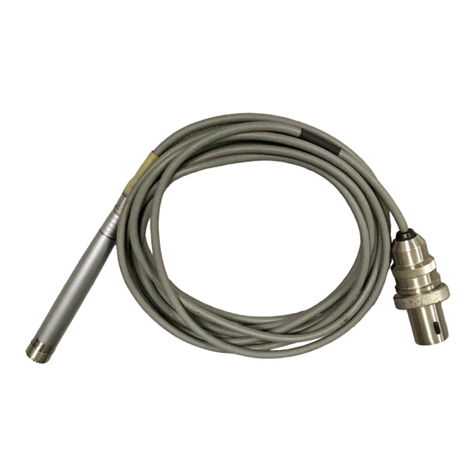
BRUEL & KJAER 4138 User guide

Eighth-inch Condenser Microphone
Microphone Cartridge Type 4138
Cathode Follower Type 2615
with Adaptor UA 0036
Precision
condenser
microphone
for
special
measurement
purpose
. Each
microphone
is
individually
calibrated.
Frequency-range
of
calibration
:
30
Hz -
140
kHz.
Dynamic
range:
76-184
dB
.
BRUEL&
IK'-'AC.R
NA:.RUM,
DENMARK
. Teleph.:
80
05 00
. Cable:
BRUKJA
. Telex:
5316
. COPENHAGEN
B B
4138
- 0300011


Eighth-inch
CONDENSER MICROPHONES
September
1967

Contents
0.
Introduction
Definitions of Free-field and Pressure Response . . . . . . . . . . . . . . . . . . . . . 3
Random
Incidence
Response (Diffuse Field Response) . . . . . . . . . . . . . . . 4
1.
Description
General
Description
of
the
Equipment
. . . . . . . . . . . . . . . . . . . . . . . . . . . . . . 5
Eighth-inch
Condenser
Microphone
Cartridges . . . . . . . . . . . .. . . . . . . . . . 6
Cleansing of the
Microphone
Diaphragm . . . . . . . . . . . . . . . . . . . . . . . . . . . . 8
Associated Cathode
Follower
Type 2615 + UA 0036 . . . . . . . . . . . . . . . . . . 8
Characteristics
of
the
Eighth-inch
Microphones
......................
12
1. Sensitivity . . . . . . . . . . . . . . . . . . . . . . . . . . . . . . . . . . . . . . . . . .. . . . . . . . . . 12
2. Frequency Response
...
...
...................
.......
........
..
12
3.
Free Field
Corrections
........................................
14
4.
Directional
Characteristics
.....................................
14
5. Dynamic Range (Noise and Distortion)
..........................
15
6. Equivalent
Air
Volume
.........................................
16
7.
Influence
of
the Polarization Voltage
............................
16
8.
Temperature
Characteristics
...................................
16
9.
Influence
of
Ambient
Pressure
......................
.....
.......
16
10. Influence
of
Humidity
..........................................
17
11. Influence
of
Vibrations
........................................
18
12. Sensitivity to
Magnetic
Fields
..................................
18
2.
Accessories
Microphone
Stand UA 0049
........................................
19
Extension Cables AO 0027-28-29, AR
0001
..........................
19
Mechanical
Adaptor
DB 0900
.......................................
20
Probe
Microphone
Kit
UA 0040
....................................
21
Two-Channel
Selector
4408
........................................
22
Microphone
Power
Supply
2801
....................................
23
Two-Channel
Power
Supply
Type 2803
..............................
24
Appendix
Principle
of
the
Condenser
Microphone
..............................
25
Microphone
Calibration
............................................
26
Pistonphone 4220
.................................................
27
Electrostatic
Actuator
UA 0033
.....................................
28
The Range
of
B & K
Condenser
Microphones
........................
30
Specifications
Survey
of
Accessories
.............................................
33
Comparative
specifications
........................................
34
0.
Introduction
Definitions.
Free-field and Pressure Response.
The Free-field Response
of
a
microphone
is
the
ratio
of
the
RMS
output
voltage to the RMS sound pressure existing in
the
free
field
at
the
microphone
location
with the microphone removed from the sound
field
.
The Pressure Response
of
a microphone is
the
ratio
of
the RMS
output
voltage to the RMS sound pressure,
uniformly
applied
over
the
diaphragm.
The
two
definitions
coincide
for
a
microphone
having
negligible
dimensions
with
respect to the sound wavelength.
At
higher
frequencies
the
diffractions
of
the sound waves on the
microphone
produce
an
appreciable
change in the resulting sound
pressure
acting
on
the
microphone
diaphragm
as illustrated in Fig. 0.1. The
difference
P
1-
po,
called
free-field
correction,
depends on the
orientation
of
the
microphone
with
respect to the
direction
of
propagation
of
the
sound and on the external
dimensions
of
the microphone (in
particular
those
of
the
front
and
of
fitted
protective
grids
or
"nose
cones").
The free-field behaviour
of
a
microphone
is thus
described
by means
of
a
set
of
free-field
correction
curves
for
various
incidences,
which
should
be
added to
the
pressure frequency curve
of
the
microphone
in each
particular
case.
For
microphones
intended
for
free-field
work
it is
possible
to
give
the
diaphragm
resonance such a damping that
the
normal
incidence
free-field
corrections
are compensated
for
up to
frequencies
well
above
the resonance
frequency, in
order
to obtain the flattest possible
frequency
response.
Free-Field Response=
~o
Pressure
Response=
;,
vo~ts
-------;rv
L__M_icroph-one
_r:::::I
S::::::::--~
-~~
Wavelength
Sound
pressure
p
0
-------~-
00incidence
f62f60
Fig. 0.1. Definitions
of
Free-field
and
Pressure
response
.
3

Random Incidence Response (Diffuse Field Response).
The random
incidence
response
of
a
microphone
for
a given
frequency
is
the RMS value
of
the
free
field
sensitivity
for
all angles
of
incidence
of
the
sound wave. It
corresponds
to the
diffuse
field sensitivity
of
the microphone,
the
diffuse
.field being a sound field in
which
the sound energy density is
uniform and the mean
acoustic
power
per
unit area is the same in all
directions.
The
International
Electrotechnical
Commission (publication no. 123,
§ 8.2) has given a
practical
rule
for
the
calculation
of
the random
incidence
sensitivity from the
free-field
sensitivities
at definite angles, with
coefficients
proportional
to the relative
solid
angles.*)
When
the
spectral
distribution
of
the sound varies with the angle
of
incidence,
correct
integration
is
only
possible
in
the
range where the
microphone
is both
linear
and
omnidirectional
(practically
up to
30
kHz with the eighth-inch
microphones).
Omnidirectional
microphones
are also necessary in the case
of
rapidly
moving sound
sources
(aeroplanes, motorcars, etc.).
*)
So, S3
o,
S
6o
----
S1so
being
the
sensitivity
of
the
microphone
at angles
of
incidence
of
oo,
30°, 60°,
----
180°,
the
random
incidence
· (diffuse field) response S
is
given by the
formula
:
S2 = 0.
018
(So2 + S
1so
2) + 0.
129
(S
3o2
+ S
1so
2) +
0.224
(S
60
2 +
S1
20
2)
+
0.258
S
902
4

1. Description
G·eneral Description of the Equipment.
A
complete
microphone
consists
of
a
microphone
cartridge
and a
cathode
follower
for
impedance
conversion, allowing long cables and relatively
low
input
impedance
amplifiers to be used between the
microphone
and
the
measuring instrument. The
microphone
cartridge
is
screwed
onto
the
housing
of
the
cathode
follower
by means
of
an
adaptor
making
a small, rugged unit.
Fig. 1.1.
2615
~
---
-+69
.
3--
--
_.,14
UA0036 4138
Fig. 1.1. Eighth-inch
microphone
with
outer
dimensions
in
mm
(1
mm
= 0.03937 inch).
The
microphone
may be
directly
connected to
the
different
B & K measuring
instruments
which
are provided with a CONDENSER MICROPHONE
input
socket
fitting the microphone connecting plug. Stabilized plate and heater
voltages
for
the
cathode
follower
and polarization voltage
for
the
cartridge
are
available on this seven-pin socket. The
microphones
may also be used with
other
equipment when operated from a Two-Channel
Microphone
Power
Supply
Type 2803
or
a
Microphone
Power
Supply
Type
2801
which
provide
the necessary voltages in the same
conditions
as the B & K measuring in-
struments (see Accessories).
For free-field and room-acoustic measurements, the
microphones
should be
placed
remote from the measuring instruments,
since
these
would
often
disturb
the sound field because
of
their
non-negligible
dimensions.
Different
types
of
microphone
stands and extension
cables
are
available
for
this
purpose, see Accessories. The length
of
cable, however, has a
significant
influence on the response above
40
kHz as will be seen in
the
description
of
the
cathode
follower.
5

Microphone
Ampl.
4138
2615
Level
Recorder
UA0036
2804
Fig. 1.2.
Typical
B &K
measuring
equipment. Both
amplifier
and
level
recorder
are
linear
up to 200 kHz. A
filter
set
(Type 1612) is also available
tor
automatic
plotting
of
spectrograms
in the range
22
Hz-45 kH
z.
Eighth-inch Condenser Microphone Cartridges.
This
B & K
microphone
cartridge
is
specially
designed
for
prec1s1on
sound
pressure measurements in
the
frequency
range
of
30 Hz to 140 kHz. This very
wide
frequency
range is
obtained
by
reducing the mechanical
dimensions
to
a minimum. For
this
very
reason,
however
, the sensitivity is quite
low
and the
microphone
is
not
well
suited
for
measuring sound pressure levels
below
76
dB
re. 0.0002
,u
bar. On
the
other
hand a dynamic range up
to
184
dB
re.
0.0002
,u
bar
and an exce-llent response to sharp pulses, because
of
the
wide
frequency
range, makes the
cartridge
well suited
for
measuring all kinds
of
noise at high pressure levels (e. g.
missile
exhaust noise etc.).
Excellent
long term
stability
under
a
great
range
of
environmental
conditions
and
especially
insensitivity
to
temperature
variations ensures
that
even
for
field measurements
the
accuracy
of
calibration
matches laboratory standard
requirements.
-70
dB
re.1V/)Jbor
- 8
0
- 9
0
-
10
0
-
11
0
-1
20,0
001
20
0.1
Type
4138 +
UA
0036+2615
0.
01
50
100
200
0.1 500 1000 2
000
5000 10000
20
000
Hz
50000 100000 200000 0.001
1
10
kHz
100
167
0 4 2
Fig. 1.3.
Most
significant
pressure
response
of
the eighth-inch
microphone
.
6

The
characteristic
of
the
Microphone
Cartridge
Type 4138 is
illustrated
in
Fig.
1.3
. It is based on
an
extremely accurate
mechanical
construction.
Fig. 1.4
shows a
cross
section
of
the
microphone
cartridge.
The
thickness
of
the
diaphragm (approximately 2 fl
),
the shape
of
the
back
plate
and
the
distance
(12
-
13
fl) between membrane and
back
plate is
determined
so
that
a
critical
damping
of
the diapragm resonance is achieved. In
this
way the
widest
possible
flat
frequency range
of
the pressure response is
obtained
.
The pressure increase with the
protection
grid
mounted is
appreciably
higher
and at high frequencies it is rather
dependent
on
how
tightly
the
grid
is
screwed onto the cartridge. Measurements involving
ultrasonic
frequencies
should
therefore
be carried out with the
protection
grid
removed.
Towards
the
low
frequencies the response
of
the
cartridges
is
only
affected
by the
influence
of
the pressure
equalizing
arrangement.
This
arrangement
Oiaphrogm
eac\1-
p\.ate
167132.
Fig. 1.4.
Exploded
view
of
a 1/8"
microphone
cartridge.
J.
Smm
Fig. 1.5. Dimensions
of
the 1/
8"
microphone
cartridge
Type 4138.
7

consists
of
a
capillary
leakage
hole
through
which
the equalization
of
the
static
air
pressure on both
sides
of
the d·iaphragm is obtained
at
a suitable
rate. The
influence
of
ambient
pressure (or altitude) variations on the
micro-
phone sensitivity has been
practically
eliminated by
proper
design
of
the
pressure equalization hole. The
time
constant
of
the pressure equalization
of
the eighth-inch
cartridges
corresponds
to a - 3 dB cut-off frequency
of
30 Hz
and
will
not
influence
the measurements, since the - 3 dB low frequency
cut-off
of
the
complete
microphone
is >5
Hz.
The
choice
of
the
materials
and
the
design
of
the suspensions of the
different
parts
are made
principally
in
order
to obtain the best possible long-term
stability
and
temperature
independency
of
the sensitivity.
In
particular
, the
diaphragm
is
not
clamped but electro-deposited onto the
tensioning ring,
forming
one
mechanical
piece. The tension
of
the diaphragm
is thereby
unaffected
by
temperature
variations. The
cartridges
are also
subjected
to a
complete
artificial
aging process during manufacture consisting
of
controlled
temperature
variations
over at least two weeks. The basic parts
are made
of
high
nickel
alloy
(K-Monel). The insulator used is
silicone
treated
quartz
and
for
guaranteeing
a
disturbance
-free connection to the
cathode
fo·llower,
gold-plated
contacts
are
used.
The diaphagm is mounted
at
a
distance
of
12-13
fl
from the
back
plate. The
polarized
cartridge
capacity
is
of
the
order
of
3.5 pF. The insulation is verified
as
higher
than 105 MQ.
Cleansing of the Microphone Diaphragm.
CAUTION. On no
account
should
the diaphragm come into
contact
with
fingers
or
other
objects.
The
protecting
grid
should
only
be removed when
absolutely necessary.
Should
the
diaphragm
become
contaminated
by
liquids
or
dust
it
may
be
dried
off
with
cottonwool
or
a very
soft
paint-brush, using
great
care,
and
if
necessary
a
proper
solvent. The diaphragm
will
not
normally
corrode
,
but
any
appreciable
added
mass
will
change the frequency response.
Associated Cathode Follower Type 2615 + UA 0036.
The
eighth-inch
microphone
cartridges
Type 4138 are intended to be used
with
the
cathode
follower
Type
2615 provided with an
adaptor
Type UA 0036.
The
"goose-neck"
cathode
follower
Type 2614 may be used instead
of
the
2615
but
it
is then
necessary
in
order
to
obtain identical results above 40 kHz
to
load the
output
of
the
2614
with
a
capacitance
of
600 pF (e.g. the 10 m long
cable
Type AO 0028).
Note: On no
account
should
it be attempted to bend the Adaptor UA 0036.
A
photograph
of
the 2615 is seen in Fig. 1.6 and the basic diagram is given
in Fig. 1.
7.
The
electrical
components
have been divided into
two
groups.
Those belonging to the
high
impedance
input
circuit
are mounted in the
main housing
containing
the
vacuum tube,
while
all parts on the
low
im-
pedance
side
are
located
in
the
connecting
plug. A
two-meter
long
multicore
cable
is inserted between housing and plug. The dimensions of the housing
8

are thus reduced to a mmtmum:
diameter
12.7 mm (1/2"), length approx.
7
em
(2%").
See also Fig. 1.1. The components,
which
are
compactly
mounted
on a teflon base, have been
carefully
selected in
order
to
ensure high
operating
stability
under the most severe environments.
Fig. 1.6. The Cathode
Followers
Type 2614
and
2615
with
included
input
adaptor
JJ
2614.
Components in
7-
poled plug
I
I
I
I
I
I
I
Cable
·-·-o
Microph~
Cartridge
~-
-----------------------1
~-----
----
--~~~sj~ll._
__
...J
t6oso7
Fig. 1.7.
Basic
diagram
of
the
cathode-follower
showing
the
principle
of
the
guard
ring
system.
9

Before
mounting
each
tube
is
tested
for
sensitivity to
shock
according
to
the
Mii-EIC
specifications
. In
addition,
during
the final
test
the
cathode
followers
are
exposed
to
a
sound
pressure
of
130
dB
where
their
microphonics
are
checked
to
be
smaller
than
8
mV
throughout
the
frequency
range
20
-20000 Hz
(Fig. 1.8).
The
input
circuitry
is
internally
screened
by means
of
a
"guard
ring"
which
is
connected
to
the
cathode
of
the
tube
. In
this
way the input
capacity
is
reduced
to
an
absolute
minimum.
The
guard ring is extended to the top
of
the
cathode
follower
which
allows
the
use
of
low
capacity
extension
con-
nectors
such as UA 0036
between
microphone
cartridge
and
cathode
follower.
The
capacitive
load
due
to
the
three
signal
conductors
of
the
multi-core
cable
causes,
through
the
guard
ring
circuit
, the
input
capacity
to
increase
with
frequency. When
adjusting
the
frequency
response
of
the
cartridge
this
loss is
taken
into
account
in
order
to
provide
a flat
frequency
response
of
the
complete
microphone.
The
power
supplies
necessary
to
operate
the
cathode
followers
are
provided
by
the
B & K
measuring
amplifiers,
or
the Two-Channel
Microphone
Power
Supply
Type 2803
or
the
Microphone
Power
Supply Type 2801 , via
the
multi
pin-
socket
at
the
front
panel as
shown
in Fig. 1.10.
I=
0 max. allowable : Level : 40dB
---.----
.
---
==
40
t1me : 1.6sec.
==
Shock
==
~
db
- -
1sec
.
t<1
.
6sec
-
==
~
==
20
---
~
10
- 0
goo B -
-----l=t=
R=
0
senes
A
ser1es
8
162167
____._
I!-
~
BmV 2615
p130 dB
acoustic
test
!=
!=
O.BmV
-
f-
o.osmv
1 1
200
500
1000
~15i'r
5000
10000 '
"'
"
100
1000 C/5
10000
liC
S0
9
Fig. 1.
8.
(a) Test
of
a tube EF 731.
Microphonics
are
excited
by
means
of
two series
of
lateral
shocks
and
recorded
whereby
the
amplitude
and
duration
of
transi-
ents
are
closely
checked.
(b)
Hecording
of
the
output
from a 1/
2"
cathode
follower
loaded
by
a 6
pF
dummy
ca
rtridge
,
exposed
to a
sound
field
of
130 dB
at
varying frequency.
10

100V
dB
> 35
..
"'
~
g 30
::>
a.
::>
~
25
~
10V
2o
15
10
dB
1V
0
- 5
-
10
I
Rt>1Mfl
~
~Rt=SOkQ
""'-r-..
""'
" ' "
~
~~
~
'-.
Rt
=10k Q
"-
~
""'
~
~
~
~
~K'
~
~'
input output
r-
J I
~+
~~
.....
,
2615
......
,
\
~
' "
~
"""
" "
"~
"""
""
"...c-
'~
~~J
~
"'
"
.;
i:?~
""~
r"\"...c-
:.O...c-
~
~
--·
~
~'
"'
~
~1?
~
'-'~-<'
~'
~
'-.',
'\
.....
,
,~,,('-
'
""''
~''~
' '
1?o
\
'',~
~'',,
~~
~
~'-,~·
,,
"~,('-
1\
r--.
..
\ ' \
1\
"-,
',
' '
' ' 3
573
0.2 0.5
10
20
kH~
50
,.
100
200
Fig. 1.9. Upper
limit
of
the dynamic range
of
the
cathode
follower. The
limit
given
by
this graph is the
peak
output
voltage
corresponding
to a
distortion
of
4 % as a function
of
frequency
and
loading. The
dashed
lines
show
the
cor-
responding
input
voltage (minus 0.9 dB).
Ground
Polarization
Voltage
200V
DC
Cathode
~
Filament
6.3V
DC
200mA
(max. ripple 2 mVolt)
Plate
150V
DC
2mA
(max. ripple
GO;.!Volt)
Connecti
on
for
4408
f
592
f6
Fig.
1.1
0.
Plug connection
of
the cathode
follower
(viewed
externally).
The cathode followers can be used separately whenever a high input impe-
dance amplifier is needed for voltage measurements at the
output
of
small
transducers etc. An input adaptor
JJ
2614
is supplied
for
this purpose with
each cathode follower, as seen in Fig.
1.6.
This
adaptor
can be screwed
onto the cathode follower housing instead
of
the UA 0036 and contains a
capacitor
of
a few thousand pF for blocking the 200 V DC polarization
11

voltage. The
adaptor
provides
a
standard
14 mm coaxial socket fitting the
B &K
JP
0018 plug.
Specifications.
Input
Impedance:
700
MQ
in
parallel
with
3 ± 0.5 pF.
Below
10 Hz and above 2 Hz: more than
200
MQ in parallel
with
3 ± 0.5 pF).
Output
Impedance:
Approximately
750
Q.
Transmission Loss:
Voltage
gain
= - 0.9
dB
± 0.2 dB.
Self-generated
Noise Level:
Approximately
80
p,
V at cathode
follower
output
,
with the
input
loaded
by a
capacitor
of
8 pF
(20
Hz-
200
kHz).
Distortion:
4%
distortion
occurs
with
input
voltages
higher
than
20
volts
RMS
at
1 kHz. (See Fig. 1.10
for
higher
frequencies).
Tube: 5899 (EF31),
specially
tested
for
low
microphonics
.
Characteristics
of
the
Eighth-inch Microphones.
1. Sensitivity.
The nominal
sensitivity
of
the
eighth-inch
microphone
is
50
p,
V/tt
bar
(-
86
dB
re 1 V
/p,
bar).
However
,
the
cartridges
are
individually calibrated and the actual
sensitivities may
lie
between
± 3
dB
of
the nominal values.
On the
calibration
chart
(Fig. 1.11)
which
is delivered with each
cartridge
is also given the
cartridge
open
circuit
sensitivity (about 5 dB
higher
than
the sensitivity
of
the
complete
microphone
depending on the
cartridge
capacity) and a
factor
K equal to
the
difference
between the
microphone
sensitivity to
which
the
sound level
graduation
of
the B & K instruments is
referred and the
particular
microphone
sensitivity.
s.;"!l:~':IJ:na.~....,~~
1
760
"'"'
Hf,
o
nd
with
tOO
Y
lll,.
...
.,...,otu\IIOd•loUoworou\put'J
•
...
92, c I'VII'l>O•
···-~
B~
7 .
dl
••
• I
V//'bU
Tomporoturo
22
__
"(:
lloromotr
lc
Pr
o
""""
7
60
-·
"'"'fll
"OIOtl•oHum
i<IIV
~
0
.• 0/o
~~=
-
IJDOOOOODOOOOOOODOODDOODOODODDOOOOOO
DD
OO
DD
_
Sign_
,
___
"-
--
,_
,
__
z-~..o.~
=---
OWtol<h - • o.12ft
ln~h
{S.1JB
"'"'\wltho"t
~
~
~
-=-
:::
.
:~::=::
;~~:~~~
"~""
0 .
0001
CM
1,
'":~'::".:!:.":.:':~.,.,
.....
n
-&O
o
nd+eo'C•
-
!1
-
~~f.~~~::::~:.:::::~
•
•::::c'!"::':o~~=~::~:
•
l.eao
U.on
o.l
dB,In
U..
-
10
Open
Circuit
Pres
~
ure
Respo
~~
~
::=:=
p;~
ssure
Response
Cbtoined
~
-
~-
With
2615
+
UA
0036
:tJ =
(
The
dott
ed
cu
rv
e
®e
or
so
n
th
elowerchort)
==!:'.=
--
•
Fig. 1.11.
Calibration
charts
supplied
with each
microphone
cartridge. The
pressure response is
automatically
plotted
by
a
process
having an
accuracy
of
± 0.2
dB
up
to
10
kHz
and
± 0.5
dB
up to
200kHz.
2.
Frequency
Response.
The
frequency
characteristics
given in Fig. 1.
11
are
the
open
circuit
pressure
response,
which
is
defined
as the ratio
of
the RMS
output
voltage
to
the RMS
Sound pressure,
uniformly
applied
over
the diaphragm, and the pressure
response
curve
obtained
on 2615 + UA 0036.
12

v..-
r-,,
00 -
/ -
~oo\'-
10
5
I I _I I
.1
J/
'\ \
1----
Free
Field Corrections
V;
\ I
1----
For Type 4138 I
f----
With Protecting Grid
_;:v
I I
/
'/
'·
I
1--
60
o I
~
/'
y I
dB
~
//
\ I I
~'/"
/ I \ I
~V"
~
I
\I
-
~
90°
I
\'
['.. I
,,
0
\ \\
I \ 'I '
..
I
-5
\ I
fil&
(
,-,
Ill
::~
~
0°
Incidence I
9
I>-
I
dB
/ I
I
-10
2kHz
3 5 7
10
15
20
30 40 50 70 100kHz
150
200
10
-
F~ee
Fi~ld
C~rre
1
cti~ns
00
-
For
Type
4138 v
~
Vlf!thout
Protectina kid /
/-
t---1'...30°
"r-...
dB v /
""
-..........
v v
"'
/ v
-~---
-r-...
60°
~
/~
v K
~
_......
v \
0
--
\
1'---
\
'I
1\
'\
goo
\
\
'\._
'\
\ \
-5
EO?&
(
(-,
I.
t
0°
Incidence \
~
1\
\
dB
-10 l
2kHz 3 4 7
10
15
20 30 40 50 70 100kHz
150
200
16115Z
Fig. 1.12. Free field corrections for the eighth-inch
microphone.
13

3.
Free-field corrections.
The free-field
correction
curves
for
incidences from 0° to 180° are given
in Fig. 1.12. They are
only
well defined
for
the microphone without protecting
grid at high frequencies because the wavelength being only a few millimeters
interfers with the
dimensions
and position of the grid slots. (The wavelength
in
air
is 1.6 mm at 200 kHz).
4.
Directional Characteristics.
From Figs 1.12 to 1.13 is seen
that
the eighth-inch microphones are omni-
directional within ± 3 dB up
to
60 kHz.
Fig.
1.13.
Directional
patterns
of
the eighth-inch microphones.
14

5.
Dynamic Range (Noise and Distortion).
The
lowe1
limit
of
the dynamic range is set by the
thermal
noise
level
of
the
cathode
follower
with input loaded by the
cartridge
capacitance.
This
noise level is less than
60
,u.V
when filtered
by
a
standard
weighting
curve A,
and about 80
p,V
when considering the maximum range 20 Hz to 200 kHz.
The
corresponding
sound level limits are 76
dB
for
a 4138 with sensitivity
50 p,V/p,bar. When
taking
measurements through
third-octave
filters
for
analysis
with B & K instruments Types 1612/2112/2211 /2212,
the
noise
level is
rejected
so as to be less than 7
p,V.
The
upper
limit
of
the
dynamic range is set by the
harmonic
distortion
which
appears both in the
cartridge
and the
cathode
follower
when the
output
voltage attains
10-20
volts (less above 40 kHz as seen
from
Fig. 1.9).
The
corresponding
sound pressure level is 185 dB.
The
level at
which
the
contact
between diaphragm and
back
plate is
possible
is
only
a
few
dB
15

above these values, and the
cartridges
should not be exposed to levels
exceeding
185 dB.
6. Equivalent Air Volume.
At
frequencies
up to 110 kHz
where
the motion
of
the microphone
diaphragm
is
controlled
only
by
stiffness, the acoustical impedance
of
the
microphone
is capacitive. In
dealing
with
closed
cavity
measurements (coupler measure-
ments) in
this
frequency
region
it
is therefore convenient to express the
impedance
in terms
of
an
equivalent
volume V.:
yP
v. = J w z.
where y = ratio
of
specific
heats (1.41) P = ambient pressure and z. =
acoustical
impedance
of
the
microphone.
The equivalent volume
of
the eighth-
inch
microphones
being, however,
smaller
than
0.0001
cm3 it will be
negligible
in the
greater
majority
of
cases.
7.
Influence of the Polarization Voltage.
The
condenser
microphone
cartridges
have been designed to operate with a
polarization voltage
of
200 volts.
The
polarization
voltage
supplied
from the instrument to which the
condenser
microphone
is
connected
should be adjusted to
200
volts before measure-
ments are taken.
Adjustment
instructions
will be found in the respective
manuals.
If
the
eighth-inch
cartridges
are operated with
other
polarization voltages
(from 150 to
250
volts)
the
sensitivity
is modified proportionally. The shape
of
the
frequency
response
curve
remains
practically
unchanged (within ± 0.2
dB). The
cartridges
are
not
tested above 250 volts.
8.
Temperature Characteristics.
As mentioned in the
description,
special
care has been taken
during
the
development
and
subsequent
manufacture
of
the microphone
cartridges
to
obtain
a
characteristic
which
to
a high degree is independent of temperature.
The
cartridges
and
adaptor
UA 0036 stand temperatures
of
up to
150°C
(300°
F)
continuously
and up to
250°C
in
short
periods
(10
min.). However, the insula-
tion
material used in
the
connecting
cables
of
the cathode
followers
2615
should
not
be
exposed to
higher
temperatures than 100°C (212°F).
Note:
Subjecting
the
eighth-inch
cartridges
to temperatures around 200°C
during
more
than 10
minutes
will
not
damage the microphones
but
will
produce
a
permanent
change
in
characteristics.
9.
Influence of Ambient Pressure.
The
microphone
sensitivity
will
vary less than
-0.1
%
for
+
10%
variations
in
ambient
pressure.
For
important
changes in ambient pressure the
fre-
quency
response
of
the
microphone
will be modified, especially
towards
16

B•Uei&Kjao• •
Meo..n.,.Objoc<
,
~
B•U
e
i&K
jao
•
oooooo
oo
ooooooooooooooooooooooooooooooooooooooooooo
~
Roa.d
•
no
No.
,
s;,n.
, J Jensen
Do•
'
12
4
67
p_ ,
__l5_dB__
z~
~.o.o~
,
b--
-1-
F-
-f-
1--
·-
1--
r,---
-1-
1--
-
2 H•
P1141
1\,t.Ronge:
Br
Uel
&
Kjc:Br
-j--
1--
-
-j--
-I-
---
-
r--
-I-
-1--
-
dB
Rectifier
.:
-
1- -
1
--
- -
--
1
-~
1000
2000
lowerllm.Fr.q.:
Hz
Writing
SpMd
:
~
1-
1--
1--
5000 10000
rrm
Hg
.
40
65
1-
235
1-
465-
·-
565
-1-
665·
:-::-c
765
-
-==
-
f- -
-
- ,.
..
-
50000
100000
mJfljs.C.
. Poper Speed:
mmf>O<
. N'll/'7
BrUel & Kjatr
ooooooooooooooooooooooooooo
o
ooooooooooooooooooooooo
~
,_
RO<oodlng
No,,
Sign
,, J. Jensen
Do
..
,
12
.4
67
z~
l~"
'
1'-
-·-
==
·- _._
.__
-
r--
-I-
-
--
--
1
-1--
-I-
'---
- -
--
--
--
-1---
--·-
-1--
-
1--
-
--1- 1
-l
--
-1--
-r-
- 1-
·-
-,
1-
-1---
-1--
-1-
-
-
-I-
-
2
Hz
S
50000
100000
[
QP1141
ll>t
.
Ranoo
'
~''"'
·
16714/J
Fig. 1.14. Influence
of
the static ambient pressure
on
the frequency response
of
the eighth-inch
microphone.
the
higher
frequencies because of the change in mechanical damping. The
frequency response at different ambient pressures is given in Fig. 1.14. The
influence
of
varying altitude is very small: a rate
of
climb
of
10 km/sec at
ground level affects the sensitivity less than 1 dB.
10. Influence of Humidity.
Large variations
of
ambient temperature may in some cases cause moisture
condensation to take place between the diaphragm and the
electrode
of the
cartridges. There is then a temporary risk
of
electrical
noise and cracking.
When stable ambient conditions are regained,
the
condensed
water
will
evaporate within less than 15 minutes through
the
pressure equalization
aperture. A complete description
of
these phenomena
will
be found in the
17

B & K Technical Review No. 1-1960, p. 12-15. A fully protected
microphone
system
for
permanent exposure
outdoors
is available in the half-inch range
(Type 2615 + 4133 + UA 0056).
In
the
absence
of
condensation,
the
relative humidity percentage has
practically
no influence on
the
microphone
sensitivity.
N.B.
The
use
of
dessicators
during
storage is not recommended.
11. Influence
of
Vibrations.
The influence
of
a
vibration
will depend on the direction in which
it
is
applied
to
the
microphone. When the
force
is acting in a direction which
is parallel
to
the
axis
of
symmetry (i.e. at right angles to the diaphragm)
the sensitivity to
vibration
is
mainly
determined by the mass
of
the diaphragm
and
of
the
air
column
on both
sides
of
it. The microphone will be most
sensitive
to
vibration
acting
in
this
direction, but due to the low diaphragm
mass,
the
signal
produced
from
vibrations
having an acceleration
of
1 g
is a
low
as an equivalent sound pressure level
of
approximately 90 dB. The
sensitivity
to
vibrations
acting
at
right
angles to the axis of symmetry (parallel
to
the
diaphragm) is
determined
by
the
electrodes
of
the cathode
follower
tube.
12.
Sensitivity
to
Magnetic Fields.
The sensitivity
to
magnetic
fields
is extremely low. Even with a very intense
field
of
50
oersted at 50 Hz having
the
most unfavorable orientation,
the
induced
output
does
not
exceeded
0.1
mV fundamental and 0.3 mV second
harmonic
(100 Hz).
18
Table of contents
Other BRUEL & KJAER Microphone manuals

BRUEL & KJAER
BRUEL & KJAER 4117 User guide

BRUEL & KJAER
BRUEL & KJAER 4188 User manual

BRUEL & KJAER
BRUEL & KJAER 4952 Quick start guide

BRUEL & KJAER
BRUEL & KJAER 4964 Guide

BRUEL & KJAER
BRUEL & KJAER 4111 User guide

BRUEL & KJAER
BRUEL & KJAER 4148 User guide

BRUEL & KJAER
BRUEL & KJAER 4184-A Guide

BRUEL & KJAER
BRUEL & KJAER 5935 Guide
Popular Microphone manuals by other brands

Potter
Potter EVAX EVX-RM installation manual

Beyerdynamic
Beyerdynamic Classis BM 32 Features & specifications

Lightspeed
Lightspeed Flexmike DAILY OPERATION INSTRUCTIONS

Behringer
Behringer DUAL DIAPHRAGM CONDENSER MICROPHONE B-2 PRO Specifications

Neumann.Berlin
Neumann.Berlin U 87 Ai operating instructions

Gembird
Gembird EMIC-PRO user manual