BRUEL & KJAER 5935 Guide

nical Documentation · Technical Documenta
tion · Technical Documentation · Techn
Documentation · Technical Docum
· Technical Documentation · T
mentation · Technical D
hnical Documentat
tation · Techni
l Docum
Technical
Documenation
t
BE1300−12
Brüel&Kjær
BK
7/6-'89
Dual Microphone Supply
Type 5935


BE1300−12 Dual Microphone Supply Type 5935 Brüel&Kjær
User Guide
November 1998
Dual Microphone Supply
Type 5935
Valid from serial number 1628016

Copyright © 1993, 1998 Brüel&Kjær A/S
All rights reserved. No part of this publication may be reproduced or distributed in
any form, or by any means, without prior consent in writing from Brüel & Kjær
A/S, Nærum, Denmark.
Safety Considerations
This apparatus has been designed and tested in accordance with IEC Publi-
cation 348, Safety Requirements for Electronic Measuring Apparatus (see
specifications), and has been supplied in safe condition. This User Guide
contains information and warnings which must be followed by the user to
ensure safe operation and to retain the apparatus in safe condition. Special
note should be made of the following:
Safety Symbols
The apparatus will be marked with this symbol when it is important that the
user refers to the associated warning statements given in the User Guide.
Chassis terminal Safety earth terminal Hazardous voltage
Warnings
• Whenever it is likely that the correct function or operating safety of the appara-
tus has been impaired, it must be made inoperative and be secured against
unintended operation.
• Any adjustment maintenance and repair of the open apparatus under voltage
must be avoided as far as possible and, if unavoidable, must be carried out only
by trained service personnel.
!

Dual Microphone Supply Type 5935
User Guide
BE1300−12 0−3
Contents
1. Functional Description................................................................................................. 5
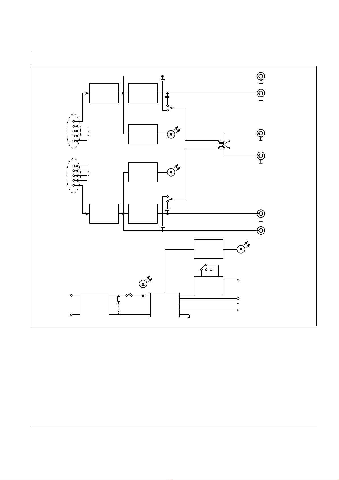
1.1 Overview ........................................................................................................................... 6
1.2 Power Source .................................................................................................................... 6
1.3 DC/DC Converter ............................................................................................................. 6
1.4 Channel Amplifier and Weighting Filter........................................................................ 8
1.5 Output Sockets ................................................................................................................. 8
2. Controls and Connections.......................................................................................... 9
2.1 Front Panel ..................................................................................................................... 10
Warning Indicators.................................................................................................... 10
Switches ..................................................................................................................... 11
Gain Adjustment ....................................................................................................... 11
Signal Connectors...................................................................................................... 11
2.2 Rear Panel ...................................................................................................................... 12
Battery Cover............................................................................................................. 12
Power Input Sockets.................................................................................................. 12
Output Sockets .......................................................................................................... 13
2.3 Bottom Panel .................................................................................................................. 13
3. Operation................................................................................................................................ 15
3.1 Applying Power .............................................................................................................. 16
Power Sources............................................................................................................ 16
Fitting Internal Batteries ......................................................................................... 16
External Supply......................................................................................................... 17
3.2 Grounding Considerations............................................................................................. 18
3.3 Polarization Voltage....................................................................................................... 18
3.4 Output Connection ......................................................................................................... 18
3.5 Input Connection............................................................................................................ 19
3.6 Setting the Gain ............................................................................................................. 20
3.7 Overload.......................................................................................................................... 21
4. Specifications ...................................................................................................................... 23
4.1 Amplifier Stages ............................................................................................................. 24
4.2 Power Supply.................................................................................................................. 25
5. Service and Repair ....................................................................................................... 5–1

Dual Microphone Supply Type 5935
User Guide Brüel & Kjær
0−4
Contents

BE1300–12 Dual Microphone Supply Type 5935 1–1
User Guide
Chapter 1
Functional Description

1–2 Dual Microphone Supply Type 5935 Brüel&Kjær
User Guide
Chapter 1 — Functional Description
Overview
1.1 Overview
The Dual Microphone Supply Type 5935 has two main functions. Firstly, the unit
supplies the necessary power requirements to attached microphone preamplifiers.
Secondly, active circuitry makes it possible to amplify the output of the preamplifi-
ers by up to +55 dB and to apply an A-weighting filter network.
These two functions apply to both channels, which operate entirely independently.
The two channels are however electrically identical, giving excellent phase charac-
teristics and minimal cross-channel differential gain.
These two functions and the two channels are shown schematically in the block
diagram, Fig.1.1. This diagram should also be referred to whilst reading the follow-
ing sections.
1.2 Power Source
In all cases, the source of power for the Type 5395 is single-polarity low-voltage DC.
This source can take several forms:
●Internal rechargeable batteries
●Internal non-rechargeable batteries
●External 12V battery
●External AC/DC converter (8–16V output)
Externally connected supplies are fed to a voltage regulator before being applied
across the internal battery terminals and, via a switch, to the input of the DC/DC
converter. This arrangement means that an external supply can be used to charge
internal rechargeable batteries, if fitted, even when the On/Off switch is off.
Warning: An external supply must never be applied when non-rechargeable batter-
ies are fitted.
The internal batteries feed the DC/DC converter, via the switch. They are protected
by a 1A fuse.
1.3 DC/DC Converter
This is the main element of the power supply section. The incoming stabilized
power from the batteries or external source is converted to a 150kHz signal, trans-
formed into the required voltages and finally rectified and smoothed. The outputs of
the converter are 0V, ±11 V, +24 V and the switchable polarization voltage of 0, 28
or 200V.
!

Chapter 1 — Functional Description
DC/DC Converter
BE1300–12 Dual Microphone Supply Type 5935 1–3
User Guide
Note: Because of the switched mode of operation, the output 0V is not referenced
to the negative terminal of the internal batteries or external source. This is to
reduce noise within the system. See section 3.2.
Fig.1.1 Block diagram of Type 5935
921798e
Overload
Output Ch. 1
(front panel)
Output Ch.2
(front panel)
Output
Swap Switch
Front Panel
Input Socket
LIN
(rear panel)
A-weighting
(rear panel)
0 - 50 dB
10 dB Steps
Heater
+ 24 V
Polarization
Voltage
A/LIN
Switch
Heater
+ 24 V
Polarization
Voltage
0 - 50 dB
10 dB Steps
Front Panel
Input Socket
A/LIN
Switch
LIN
(rear panel)
A-weighting
(rear panel)
DC/DC
Converter
Voltage
Regulator
Voltage
Divider
028200
200 V
Battery
Low
Polarization
Voltage
+ 24 V
– 11 V
+ 11 V
On/Off
Fuse
+ ve
– ve
External
Supply
Input
(8V - 16 VDC)
A Weighting
Filter
Variable Gain
Buffer Amplifier
Overload
Detector
Overload
Detector
Detector
Internal
Battery
Channel 1
Channel 2
Overload
Power On
Variable Gain
Buffer Amplifier A Weighting
Filter

1–4 Dual Microphone Supply Type 5935 Brüel&Kjær
User Guide
Chapter 1 — Functional Description
Channel Amplifier and Weighting Filter
1.4 Channel Amplifier and Weighting Filter
The output of an attached microphone preamplifier passes through an amplifier
stage before being sent either to the A-weighting filter or directly to the output
sockets. This amplifier stage, identical for each channel, has a high input imped-
ance and a very low output impedance, ideal for buffering microphone preamplifi-
ers, particularly when long microphone cables are used.
The amplifiers have switchable gain from 0dB to 50dB in 10dB steps. There is
also a front-panel screwdriver adjustment which has a range of ±5dB. This ar-
rangement, together with the switched gain stage, allows you to set up the opti-
mum input level for the next piece of equipment in the signal chain. The front-
panel screwdriver adjustment is fine enough to exactly balance the output of two
microphone preamplifiers when precise level matching is needed.
An overload detector is fed from each channel to warn when the signal passing
through the unit is approaching maximum level.
An active A-weighting filter comes after the amplifier stage. This filter has IEC
Type 0 characteristics.
The Lin. (un-weighted) outputs of the channels are closely phase matched.
1.5 Output Sockets
There are two output sockets on the front panel and four on the rear panel. The
signals appearing on these sockets come from different parts of the active circuitry
and are a combination of un-weighted signals and A-weighted signals, either AC- or
DC- coupled.
The front panel sockets are AC-coupled and are fed either with the un-weighted
amplifier signal or the A-weighted signal, depending upon the position of the A/Lin.
switch. Furthermore, there is a switch arrangement to allow the sockets to swap
channels, so that, for example, channel 1’s output appears on channel 2’s front-
panel output socket.
The LIN and A-weighted output sockets on the rear panel are DC coupled, and
cannot be swapped.

BE1300–12 Dual Microphone Supply Type 5935 2–1
User Guide
Chapter 2
Controls and Connections

2–2 Dual Microphone Supply Type 5935 Brüel&Kjær
User Guide
Chapter 2 — Controls and Connections
Front Panel
2.1 Front Panel
The front panel of the Type 5935 is shown in Fig.2.1.
2.1.1 Warning Indicators
There are three type of warning indicator on the front panel of the Type 5935:
Fig.2.1 Front panel
Power On:indicating that power from either internal or external sources is
reaching the power supply section.
Batt. Low:indicating that the supply to the DC/DC converter, from either the
batteries or external supply, has fallen below 2.7V.
Overload:indicating that the signal level in the amplifier chain is reaching
clipping point.

Chapter 2 — Controls and Connections
Front Panel
BE1300– 12 Dual Microphone Supply Type 5935 2–3
User Guide
2.1.2 Switches
2.1.3 Gain Adjustment
2.1.4 Signal Connectors
On/Off:applies power to the unit from the power-supply input section of the
unit. It should be noted that the switch comes after the external supply
voltage regulator. This means it is possible to recharge the batteries
whilst the unit is apparently off.
swaps the output sockets on the front panel with the channel outputs
inside the unit. When in the cross position, the output of channel 1 is
sent to the Ch.2 front panel output socket, and the output of channel
2 is sent to the Ch.1 front panel output socket. The rear-panel sockets
remain unaffected.
A/Lin.: sends either the A-weighted signal (A) or the un-weighted signal (Lin.)
from the amplifier AC-coupled output to the front-panel output socket.
The rear- panel sockets remain unaffected.
Gain dB:this knob selects the channel gain in steps of 10 dB from 0 dB to +50 dB.
Sens. Adj.: this screwdriver adjustment allows the gain of the channel to be
continuously varied over a range of ±5 dB.
Input: a standard Brüel & Kjær 7-pin preamplifier socket is provided for each
channel. When plugged in, the preamplifier receives its drive voltage,
the microphone-capsule polarization voltage, and the microphone
heater voltage (if applied on rear panel) from the Type 5935 power
supply. The preamplifier output signal also passes into the unit’s
amplifiers through this connector.
Output:the AC-coupled output of each channel appears on unbalanced BNC
sockets. The source of the signal, Ch.1 or Ch.2, depends upon the
position of the changeover switch. The type of signal, Lin. or A-
weighted, depends upon the position of the A/Lin. switch.

2–4 Dual Microphone Supply Type 5935 Brüel&Kjær
User Guide
Chapter 2 — Controls and Connections
Rear Panel
2.2 Rear Panel
The rear panel of the Type 5935 is shown in Fig.2.2.
2.2.1 Battery Cover
The knurled knob at the top of the rear panel gives access to the battery compart-
ment, which lies under the top panel.
2.2.2 Power Input Sockets
Note that it is not recommended to use the same supply for the heater and the
external supply. See section 3.2 for more details.
Fig.2.2 Rear Panel

Chapter 2 — Controls and Connections
Bottom Panel
BE1300– 12 Dual Microphone Supply Type 5935 2–5
User Guide
2.2.3 Output Sockets
There are four output sockets on the rear panel, two for each channel. The signals
appearing on these sockets are independent of the front panel changeover switch
arrangement. The descriptions below apply to both channels.
2.3 Bottom Panel
The bottom panel gives access to the microphone polarization voltage switch and
the battery fuse. The slotted fitting at the bottom of the front panel is turned anti-
clockwise and the bottom panel is slid out. The polarization switch is on the right of
the printed circuit board. The battery fuse, 1A, is located on the bottom of the
battery holder.
Note: On no account should any of the trim potentiometers now accessible be
touched. Changing them causes the unit to be mis-aligned and not be within speci-
fication. Re-alignment to specification can only be carried out by Brüel&Kjær repre-
sentatives.
External
Supply:this 7-pin DIN-standard socket allows you to connect an external power
supply. The supply should give between 8VDC and 16 VDC, and be
capable of supplying up to 200 mA. The supply need not be smoothed,
as the internal circuitry in the unit provides the necessary voltage
stabilization.
This symbol by the side of the external supply socket is a warning that external
supplies must never be applied when using non-rechargeable batteries. There is a
risk of explosion.
Heater
Input:the two 4mm “banana” sockets allow you to connect a 12VDC supply
to feed the heater element in some microphones. The sockets are
marked with + to represent the positive connection to the heater supply
and ⊥to represent the earth or ground connection.
Lin. this is the low impedance un-weighted output of the channel amplifier.
The output is DC-coupled.
Athis is the low impedance IEC Type 0 A-weighted output. The output
is DC-coupled.
!

2–6 Dual Microphone Supply Type 5935 Brüel&Kjær
User Guide
Chapter 2 — Controls and Connections
Bottom Panel

BE1300–12 Dual Microphone Supply Type 5935 3–1
User Guide
Chapter 3
Operation

3–2 Dual Microphone Supply Type 5935 Brüel&Kjær
User Guide
Chapter 3 — Operation
Applying Power
3.1 Applying Power
3.1.1 Power Sources
There are four main sources of power for the Type 5935:
●Internal rechargeable batteries
●Internal non-rechargeable batteries
●External 12V battery
●External AC/DC converter (8–16 V output).
When any of these sources is connected correctly and the On/Off switch is in the On
position, the Power On LED lights. If internal batteries are being used and the
LED does not light, first check the battery orientation and then the fuse. The 1A
fuse is located on the bottom of the battery holder and can be accessed after remov-
ing the bottom cover.
3.1.2 Fitting Internal Batteries
The internal batteries are housed in a compartment under the top cover of the unit.
To gain access to the compartment, the knurled knob on the rear panel is un-
screwed anticlockwise and the instrument’s top cover slid out. Batteries can then be
inserted or replaced, taking care to use the correct orientation. The orientation is
shown pictorially on the inside barrels of the battery holders. (See Fig.3.1).
Fig.3.1 Internal view from top, showing battery holders

Chapter 3 — Operation
Applying Power
BE1300–12 Dual Microphone Supply Type 5935 3–3
User Guide
The Type 5935 uses three IEC LR20/D size batteries. Rechargeable batteries
(Brüel&Kjær QB 0008), when fully charged, give approximately 25 hours of contin-
uous use. When using non-rechargeable alkaline batteries (Brüel&Kjær QB 0004),
this figure is increased to 70 hours.
3.1.3 External Supply
An external supply connected to the Type 5935 should have a DC output voltage in
the range 8V to 16V, and be capable of supplying up to 200mA. These criteria can
be fulfilled in a number of ways, for example:
●Brüel & Kjær Power Supply ZG 0113
●Brüel & Kjær Power Supply ZG 0283
●12 V car battery for mobile installations
●Variable DC bench power supply
In all cases the power is applied via the 7-pin DIN external supply connector on the
rear panel. Fig.3.2 shows the connections required.
Note – there is no fuse protection in the external supply circuitry in the Type
5935.
Warning: An external supply must never be applied when non-rechargeable batter-
ies are fitted. The external supply circuitry is always connected to the battery ter-
minals via a charging circuit. There is a danger of explosion if non-rechargeable
batteries are “charged” in this way.
When an external supply is connected and there are rechargeable batteries in the
Type 5935, the batteries receive a charge current. If the On/Off switch is in the On
position, the charge current is limited to 60mA.
Fig.3.2 External supply connections (internal view)
921883e
7
3
524
1
6
Negative
Positive
(8V to 16V DC)
!

3–4 Dual Microphone Supply Type 5935 Brüel&Kjær
User Guide
Chapter 3 — Operation
Grounding Considerations
Caution – there is no indication that the batteries are being charged when the
On/Off switch is in the Off position and an external supply is connected.
3.2 Grounding Considerations
The signal path in the Type 5935 is referenced to the chassis of the unit. The
output connectors, the ground for the preamplifiers and the heater input also use
this reference ground. However, the negative terminal of the external supply, pin 2,
is isolated from this ground. This arrangement is used to reduce the noise level in
the signal path. The DC/DC converter uses the switched mode principle with a
switching frequency of 150 kHz. It is not desirable to have harmonic components of
the switching frequency in the signal chain, as this would add unwanted noise, so
the external supply circuitry is kept separate from the amplifier circuitry.
Under certain circumstances it may be required to link the external supply ground
and the signal ground. This is not dangerous, but may result in the noise levels
being out of specification. An example where this linking may be used is in a
mobile situation, where the same 12 VDC battery is used to feed both the heater
supply and the external supply.
3.3 Polarization Voltage
The Type 5935 provides the necessary polarization voltages necessary for all the
Brüel& Kjær range of microphones. The microphone receives this voltage via the
preamplifier. It is important to set the correct polarization voltage for the micro-
phone capsule being used. This is done with the polarization switch found by re-
moving the bottom cover. Fig. 3.3 shows the position of the switch.
The polarization voltage switch has three positions, 0 V, 28V and 200 V. Choice of
polarization voltage depends upon the microphone used. Refer to the microphone’s
calibration chart to find the correct polarization voltage to be used.
Note that, due to high impedances giving slower charge flow, it takes at least one
minute for the microphone capsule and polarization power supply to become stable.
Therefore it is necessary to allow the system to rest after power is applied or after
the preamplifier is attached.
The same polarization voltage is applied to both channels simultaneously. It is not
possible to have capsules with different polarization voltages working at the same
time.
3.4 Output Connection
All the outputs from the Type 5935 appear on unbalanced BNC connectors. The
outputs are all very low impedance and are designed to drive into the input circuit-
Table of contents
Other BRUEL & KJAER Microphone manuals

BRUEL & KJAER
BRUEL & KJAER 4117 User guide

BRUEL & KJAER
BRUEL & KJAER 4952 Quick start guide

BRUEL & KJAER
BRUEL & KJAER 4964 Guide

BRUEL & KJAER
BRUEL & KJAER 4184-A Guide

BRUEL & KJAER
BRUEL & KJAER 4111 User guide

BRUEL & KJAER
BRUEL & KJAER 4138 User guide

BRUEL & KJAER
BRUEL & KJAER 4148 User guide

BRUEL & KJAER
BRUEL & KJAER 4188 User manual