BRUEL & KJAER 4111 User guide

4111
INSTRUCTIONS
AND
APPLICATIONS
Condenser
Microphone
Type
4111
Specially
designed
for
measurement
and
calibration
applications,
this
Condenser
Microphone
features
very
high
stabilit
y, a
high
linea
r
frequency
response
together
with
small
dimension
s.
BHUEL
&
KJJEK
Naerum,
Denmark
.
Phone
Naerum
500.
Telegrams:
BRUKJA,
Copenhagen
Beat frequency oscillators
Low frequency oscillators
Deviation
test
bridges
Strain gauge apparatus
Frequency measuring bridges
Distortion measuring bridges
Heterodyne voltmeters
Audio
f~uency
spectrometers
Frequency analyzers
Level
recorders. a. c. and d. c.
Automatic frequency response
recorders
Automatic
A.
F.
spectographs
Logarithmic potentiometers
Noise level potentiometers
Recording paper
Polar diagram recorders
Vacuum tube voltmeters
Wide range vacuum tube
voltmeters
Diode voltmeters
D.
C.
voltmeters
Megohmmeters
~icrophone
amplifiers
Impact sound generators
Acoustic standing
wa.,.
apparatus
Artificial ears
Condenser microphones
Microphone calibration
apparatus
Vibration pick-ups
Integration networks
Rotary selectors
Universal selectors
Freqllency response tracers
Conductivity meters
Electronic counters
Counting
rate
meters
Impulse generators
Portable dose
rate
meters
Portable counting
rate
meters
G.
M.
tubes·& accessories
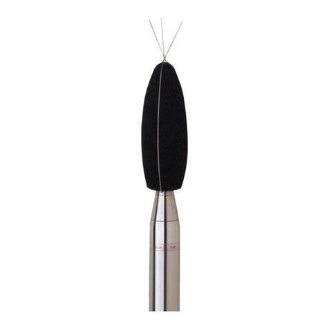
CONTENTS
Page
Description
Connections
9
Measurements
of
Sound
Pres
sure
Level
. . . . . . . . . . . . . . . . . .
13
Noise
Measurements
. . . . . . . . . . . . . . . . . . . . . . . . . . . . . . . • . • • .
20
Control
of
Frequency
Response
and
Sensitivity
of
Condenser
Microphone
4111................
23
Calculation
of
Sensitivity
. . • . . . . . . . . . . . . . . . . • . . . . . . . . . . .
29

DESCRIPTION
The
Condenser
Microphone
type
4111
is
particularly
designed
for
mea-
surement
applications
and
has
therefore
a
very
high
stability
and
com-
paratively
small
dimensions.
It
is
built
up
of
a
cartridge
directly
con-
nected
with
a
cathode
follower
tube,
making
it
possible
without
any
dif-
ficulty
to
use
long
cables
between
the
microphone
and
the
following
amplifier.
The
polarization,
anode
and
filament
voltages
to
the
ca-
thode
follower
and
cartridge
are
all
taken
from
the
amplifier,
which
is
why
only
Microphone
Amplifier
type
2601
and
Frequency
Analyzer
type
2105
or
2109
can
be
used.
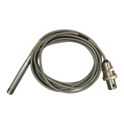
Fig.
1.
Photo
of
Condenser
Microphone
type
4111.
All
the
above
mentioned
apparatus
is
proviC::.ed
with
a
special
built-in
rectifier,
w
hich
delivers
d.
c.
current
for
filament
to
the
cathode
fol-
lo
wer
in or
der
to
retain
a
low
hum
level.
T he
cartridge
is
mounted
in
the
end
of
a
tube
(diameter
36
mm,
length
9u
mm),
which
also
contains
the
cathode
follower
with
componeq.ts.

2
Fig.
2
shows
an
exploded
view
of
the
instrument.
The
other
end
o.
the
tube
tapers
and
continues
as
a
self-supporting
goose
neck
with
a
length
of
400
mm.
This
terminates
in
a
7-pin
plug,
directly
fit-
ting
the
socket
marked
"Condenser
Microphone"
on
the
amplifier
or
analyzer.
It
is
thus
possible
to
mount
the
microphone
directly
on
the
above
mentioned
3
pieces
of
apparatus.
By
bending
the
goose
neck
the
microphone
can
then
be
placed
in
any
desired
position.
Fig.
2.
Explodea
view
of
Condenser
Microphone
type
4111.
The
sensitivity
of
the
microphone,
about
2
mV
per
fbar,
is
compara-
tively
high,
particularly
when
taking
into
acc..ount
its
small
dimens-
ions
and
high
re~onance
frequency.
The
accurate
sensitivity
of
each
individual
microphone
as
well
as
the
total
frequency
response
charac-
teristic
are
shown
on
a
recording
in
the
back
cover,
made
individually
for
each
r."licrophone
delivered.
Fig.
3
shows
an
arbitrary
example
of
such
a
calibration
curve.
Both
the
sensitivity
(ex,pressed
in
mV/fbar
(==dynes/
em
2)
or
decibels
below
1
volt/fbar)
and
the
frequency
response
are
valid
for
the
sound
waves
of
a
free
sound
·
field
impinging
normal-

3
ly
on
the
microphone
membrane,
with
the
protective
grid
removed.
(A
correction
for
the
influence
of
this
grid,
which
under
routine
mea-
surements
should
be
employed
in
all
cases,
follows
on
p.
5 ).
The
straight
curve
from
15
to
20.
ooo
c/s
is
the
response
of
the
cathode
follower
alone
(with
a
capacity
of
5.
ooo
pF
across
the
input).
The
factor
k
is
the
distance
of
the
membrane
above
the
edge
of
the
car-
tridge,
which
is
a
necessary
datum
when
checking
the
sensitivity
by
:neans
of
the
Electrostatic
Actuator
type
4113
(see
p.
24).
11
..
w,_
;
,......_,.
,.......
.,.
IIP4_,.
c
adlo4e
t.ll
--
~h
lctl
utr
l
4te
It
c.ca4
.
*···
·
-
~
.
~
~~~.::~:f!J;:r
;
;;~yr.:.~
;
~
:
.~~
:
-~;;
~
M.
POCMt
!.mettor:
l$4!.
DM•
11
1:6 •
$S
SI
I"·
...
Ief8
.
Fig.
3.
Example
of
an
individual
calibration
·
curve
for
the
microphone
fitted
with
a
specified
cartridge
and
with
a
specified
polarization
voltage.
The
microphone
is
adjusted
so
that
its
frequency
response
characte-
ristic
is
as
flat
as
possible
for
zero
angle
of
incidence.
The
fre-
quency
range
is
from
20
c/s
to
16.ooo
c/s,
of
which
the
range
30
c/s
to
10
kc/s
is
linear
to
within
±2
db.
The
f.i
rst
resonance
fre-
quency
is
about
11
kc/s.
When
a m i
crophone
is
placed
in
a
free
sound
f~~ld,
a
pressure
in-
crease
on
the
microphone
membrane
is
got,
co¢pared
with
the
sound

4
pressure
of
the
free
travelling
sound
wave,
on
account
of
the
scat-
tering
effect
of
the
microphone
at
higher
frequencies,
dependent
on
the
wave
length
of
the
sound
and
the
dimensions
of
the
microphone.
This
pressure
increase
for
normally
impinging
sound
waves
is
given
in
db
in
fig.
4.
In
order
to
obtain
a
flat
response
in
a
free
sound
field,
i.e.
a
constant
electrical
output
of
the
microphone
versus
fre-
quency,
for
a
constant
free
field
sound
pressure
prior
to
the
intro-
duction
of
the
microphone
in
the
field,
the
frequency
characteristic
of
the
microphone
measured
under
constant
pressure
conditions,
where
a
constant
sound
pressure
is
applied
to
the
diaphragm,
must
decrease
for
frequencies
higher
than
Z.ooo
c/s.
d6
1D
s
0
-s
-10
0 50
100
200
1000
ell
2k
5k
IOk
Fig.
4.
Pressure
increase
on
microphone
diaphragm
due
to
diffraction
around
a
Condenser
Microphone
type
4111
mounted
in
a
free
sound
field
{with
protective
gricJ
removed
and
with
the
sound
wa
v
es
i
mpinging
normally).
The
actuator
measurement
as
described
on
page
24
for
the
determi-
nation
of
the
frequency
characteristic
simulates
such
constant
pres-
sure
conditions.
Therefore,
if
that
measuring
procedure
should
be
employed
for
checking
the
microphone,
fig.4
should
be
added
alge-
braically
to
the
resulting
recorded
curve
in
order
to
obtain
the
free

5
field
response
of
the
microphone.
-
-----
- - - -- -
--
--
--
-
J 0
()
0
()
()
0 u
()
()
u 0 0 0 0 0 0 0 0 0 0 0 0 0 0 0 0 0 0 c
~
-f-
-
-
·-
db~
=
=\
:_
..
-
-
--!
- - . -
_-,- _
__:
_
~
-10
'b·/
-15 0 50
100
200 500
1000
CIS
2k 5k
10k
15k
20
'J 0 0 0 0 0 0 0 0 0 0 0 0 0 0 0 0 0 0 0 0 0 0 0 0 0 0 0 0 0 c
Fig.
5.
Corrections
to
be
added
to
the
calibration
curve
of
fig.
3
to
find
the
sensitivity
and
frequency
response
under
a)
free
field
measurements,
l)
degree
(normal)
incidence
with
protective
grid,
b)
free
field
measurements,
90°
(grazing)
inc
ide
nee,
with
protective
grid,
c)
free
field
measurements,
random
incidence,
with
protec-
tive
grid.
The
frequency
response
of
fig.
3
was
valid
in
a
free
sound
field
with
normally
impinging
sound
and
protective
grid
removed.
Fig.
5,
a,
b
and
c
show
three
corrections
which
should
be
algebraically
added
to
this
curve
or
to
the
corresponding
curve
valid
for
the
microphone
de-
livered,
and
placed
in
the
back
cover
.
in
order
to
get
the
right
ca-
libration
curve
under
the
following
measuring
procedures:
1)
Free
field
measurements,
0
degree
incidence
with
protective
grid.
Fig.
5a
indicates
the
diffe
renee
in
sensitivity
for
the
microphone
with
and
without
grid.

6
2)
Free
field
measurements,
90
degrees
incidence
with
protective
grid.
Fig.
Sb
indicates
.the
difference
in
sensitivity
for
the
micro-
phone
with
grid
under
90
degrees
incidence
and
without
grid
for
nor-
mal
incidence.
3)
Measurements
in
diffuse
sound
fields
with
random
incidence.
Fig.
Sc
indicates
the
difference
in
sensitivity
for
random
incidence
with
grid,
compared
with
0
degree
incidence
without
grid.
These
coJ.·rections
are
only
dependent
on
the
geometrical
form
of
the
microphone,
and
may
therefore
be
assumed
constant,
and
used
for
finding
the
corresponding
sensitivity
for
any
microphone
delivered,
for
which
the
free
field
0
degree
incidence
frequency
response
is
given.
"
'J
0 Cl 0 0 0 0 0
lJ
0 r l 0
()
0 0 0 0 0 0 0 0 0 U
rJ
0
Cl
D
()
()
0
t-1-t--
dbr
-H
- - -
-
r-
- - I
.:1
I I
-
t--t
--
0o 50
100
200 50(1
1000
CIS
u u u 0 0 0 0 0 0 0 0 0 0 0 0 0 2k
0 0
l
l
ll..I""""""~.LU,;l--1~
~.
•.
CI,
l
It
li
5k
10k
15k
20
0 u 0 u 0
()
(I (I
l 1 U
()
l'
Fig.
6.
The
corrections
of
fig.
5,
a,
b,
c,
performed
on
the
arbitrary
example
of
a
calibration
curve
of
fig.
3.
The
result
of
these
three
corrections
carried
out
on
the
curve
of
fig.
3
is
shown
in
fig.
6,
where
curve
a
represents
the
free
field
0°
incidence
sensitivity
as
a
function
of
frequency,
curve
b
the
free
field

7
90°
incidence
sensitivity,
curve
c
the
random
sensitivity.
The
directional
characteristics
(as
recorded
with
the
aid
of
the
Polar
Diagram
Recorder
type
2370)
of
Condenser
Microphone
4111
are
given
in
fig.
7
for
frequencies
up
to
9
kc/s.
Once
again,
the
geometrical
form
of
the
microphone
determines
the
shape
of
these
curves
principal-
ly,
so
that
they
can
be
used
for
any
type
4111
microphone.
The
curves
are
taken
with
the
protective
grid
mounted
on
the
cartridge.
Fig.
7.
Di
'
rectional
characteristics
of
Condenser
Microphone
type
4111
with
protective
grid
mounted.
The
sensitivity
s
mV/fbar
as
indicated
on
the
graph
in
the
back
cover
is
the
electrical
output
.after
the
cathode
follower
for
a
free
sound
wave
of
pressure
level
l
fbar,
impinging
perpendicularly
on
the
dia-
phragm.
This
output
results
initially
from
the
voltage
as
generated
by
the
cart
ridge,
which
is
attenuat<::d
in
two
ways.
First
there
is
a
loss
of
sensitivity
owing
to
the
input
capacity
of
the
cathode.
fol-

8
lower.
This
capacity
(
Cf)
is
about
10-15
pF
and
the
cartridge
capa-
city
(C
)
is
around
50
pF.
c
The
added
capacity
of
the
cathode
follower
will
decrease
the
sensitivity
·
by
the
ratio
of
Cc
to
Cc
+
Cf"
The
sen-
sitivity
loss
owing
to
this
capacity
in
the
cathode
follower
is
around
1 1I 2 - 2
db.
Secondly,
the
cathode
follower
will
cause
the
drop
A/
A + 1
where
A
represents
the
amplification
obtainable
without
feed-
back;
this
drop
amounts
to
o.
5
db.
The
sensitivity
is
measured
with
a
polarization
voltage
as
indicated
on
the
calibration
curve
of
the
cartridge.
If
the
microphone
is
attached
to
an
analyzer
the
polarization
of
which
is
different
from
that
with
which
the
microphone
has
been
measured,
a
correction
for
the
difference
in
polarization
voltage
must
be
made,
the
sensitivity
being
directly
proportional
to
the
polarization
voltage.
The
polarization
voltage
given
by
the
Analyzer
type
2105
should
be
measured
with
a
precision
voltmeter
with
max.
50
fA
current
con-
sumption.
When
this
is
done
one
e
for
all,
the
polarization
voltage
should
be
marked
on
the
condenser
microphone's
sensitivity
curve,
and
the
condenser
microphone's
absolute
sensitivity
should
be
corrected
to
the
right
polarization
voltage.
If
the
analyzer's
voltage
regulator
tube
V6
is
replaced
for
any
reason
the
polarization
voltage
must
once
again
be
measured.
For
practical
reasons,
the
sensitivity
is
given
as
defined
above,
in-
stead
of
the
open
circuit
voltage
of
the
microphone
cartridge
when
working
into
an
infinite
impedance,
as
required
by
the
American
Stan-
dard
Z
24.
4.
With
the
microphone
used
in
combination
with
Micro-

9
phone
Amplifier
2601
or
Analyzer
2105
or
2109,
a
reference
voltage
can
be
put
on
the
input
of
one
of
the
last
instruments.
The
cathode
follower'
s
output
is
then
compared
with
this
reference
voltage
and
gives
at
once
the
applied
sound
pressure
with
the
aid
of
the
micro-
phone
sensitivity
as
defined.
The
temperature
coefficient
for
the
whole
microphone
4111
is
less
than
o.
o2
db
per
degree
centigrade
in
the
range
-20
to
+60°
C,
while
the
change
in
sensitivity
caused
by
a
variation
in
humidity
is
negligible.
The
response
is
linear
up
to
a
voltage
output
of
20
volts,
and
the
dis-
tortion
is
less
than
1
o/o
for
sound
pressure
levels
up
to
120
db
above
-4
the
reference
value
2.
10
fbar,
and
less
than
411/o
for
sound
pressure
levels
up
to
140-160
db.
Higher
sound
levels
will
damage
the
micro-
phone
diaphragm.
CONNECTIONS
Microphone
Amplifier
2601:
The
socket
.
for
the
condenser
microphone
is
here
placed
on
the
top
of
the
apparatus,
so
that
the
amplifier
can
act
as
a
stand
for
the
microphone.
In
order
to
secure
a
solid
con-
nection
between
the
microphone
plug
and
socket,
the
plug
is
provided
with
a
union
nut
for
screwing
over
the
socket.
An
input
switch
selects
either
this
condenser
microphone
or
the
single
pole
input
on
the
front
side
of
the
apparatus.
Analyzers
2105
and
2109:
The
condenser
microphone
socket
is
here
placed
on
the
front
side
of
the
instruments.
In
this
case
the
input

..
10
4111
a
c
.::.
.
~
d
e .
..
.
Fig.8.
Accessories
for
Condenser
Microphone
type
4111.
a)
Floor
Stand
type
4122,
b)
Extension
Cable
type
4114,
c)
Spare
Condenser
Microphone
Cartridge
MK
0001,
d)
Electrostatic
Actuator
type
4113,
e)
Extension
Rod
type
4115,
f)
Support
type
4116.
switch
sele
.
cts
one
of
three
possible
connections:
"Condenser
Micro-
phone",
"Direct
Input"
-
where
the
coaxial
input
is
directly
connected
to
the
grid
of
the
first
tube
in
the
apparatus
-
and
"Potentiometer''•
where
a
potentiometer
is
inserted
in
this
last
connection.
Both
in-
struments
are
equipped
with
an
indicator
allowing
reading
both
in
volts,
decibels
or
phons.
To
extend
the
distance
between
the
measuring
site
and
observer
or
condenser
microphone
to
the
indicating
instrument,
the
following
ac-
ces
sories
are
available
(see
figs.
8,
9
and
l 0 ).

11
Fig.
9.
Microphone
.Ainplifier
type
2601
connected
to
Condenser
Mi-
crophone
type
41
11
via
a)
Floor
Stand
type
4122,
b)
Extension
Rod
type
4115,
c)
Extension
Cable
type
4114.
Floor
Stand
type
4122,
consisting
of
two
telescopic
steel
tubes,
the
lower
one
mounted
on
a
solid
cast
iron
foot,
the
movable
upper
part
provided
with
a
ring
for
fixing
the
plug
housing
of
Extension
Cable
4114
in
which
the
microphone
is
to
be
placed.
The
height
from
ring
to
ground
can
be
adjusted
between
110
and
200
em.
With
the
micro-
phone
stretched
upwards
this
corresponds
with
a
height
between
160
-
210
em.

12
Fig.
10.
The
same
as
fig.
9
for
the
combination
Analyzer
2105
and
Con-
denser
Microphone
type
4111.
The
arrow
shows
the
Support
type
4116.
Extension
Cable
type
.
4114
of
10
metres
length,
for
those
applications
where
the
microphone
is
held
in
the
hands
(for
example,
in
the
case
of
vibration
difficulties),
suspended
or
mounted
in
Floor
Stand
type
4122.
This
extension
cable
has
proved
to
be
extremely
valuable
in
many
ap-
plications.
Extension
Rod
4115
an~port
4116.
The
rod
is
provided
with
a
toggle
joint
movabl
e
through
90
degrees,
and
can
be
used
either
on
Anal
y
zers
2105
and
..:.
109
o;
on
the
Microphone
Amplifier
2601.
The

13
Support
4116
is
used
on
the
analyzers
simply
for
keeping
the
rod
in
position.
Figs.
9
and
10
show
complete
set-ups
for
both
Microphone
Amplifier
2601
and
Analyzer
2105,
together
with
the
accessories
men-
tioned.
The
arrow
in
fig.
10
indicates
the
support
4116.
The
Condenser
Microphone
4111
is
usually
delivered
in
a
case
with
place
for
both
microphone
and
extension
rod.
MEASUREMENTS
OF
SOUND
PRESSURE
LEVEL
With
precision
measurements
of
sound
pressure,
care
must
be
taken
that
the
microphone
is
placed
in
the
sound
field
remote
from
any
dis-
turbing
reflecting
objects,
and
the
microphone
membrane
should
be
directed
towards
the
sound
source,
as
its
adjustment
curve
is
based
on
the
sound
waves
striking
the
membrane
perpendicularly.
If
it
is
believed
that
the
microphone
amplifier
or
analyzer
itself
has
a
dis-
turbing
effect
on
the
sound
field,
it
is
recommended
to
use
the
Micro-
phone
Stand
type
4112
or
the
Extension
Cable
4114,
with
a
length
of
10
metres.
The
Microphone
Amplifier
2601
is
primarily
meant
as
an
amplifier
for
the
High
Speed
Level
Recorder
2304
for
recording
noise
levels,
frequency
characteristics,
measurement
of
sound
insulation,
rever-
beration
time,
etc.
The
instrument
is
therefore
not
equipped
with
an
indicating
meter,
although
a
VT
Voltme~er,
e.
g.
type
2407,
can
be
used
for
this
purpose
by
connecting
it
to
the
output.
The
dynamic
range
of
the
microphone
amplifier
is
kept
high
for
these
measurements
by
having
the
amplifier
tubes
d.
c.
heated.
Sound
levels
can
be
recorded

14
both
in·
decibels
and
phons,
as
the
instrument
also
includes
the
three
antisonoric
frequency
curves
for
0-30,
3\J-
60
and
60-130
phons,
con-
structed
according
to
the
standards
DIN
5045
and
ASA
Z
24.
3,
which
are
ve
.
ry
close
to
each
other.
(See
p.
?.1).
~60f
@
®
•
Fig.
11.
Recording
of
sound
pressure
level
or
noise
level
on
Level
Recorder
2304
and
direct
adjustment
of
the
combination
Microphone
Amplifier
2601
-
Level
Recorder
23\J4
to
obtain
calibrated
ordinate
values
on
the
recording
paper.
When
the
condenser
microphone
is
employed
together
with
the
Micro-
phone
Amplifier
2601
and
the
Level
Recorder
2304,
and
a
recording
of
any
kind
of
sounc;l
or
noise
is
wanted,
together
with
the
absolute
values
of
the
sounr
pressure
or
noise
level,
the
method
of
fig.
11
can
be
used.
The
10
j
mV
reference
voltage
of
the
level
recorder,
which
I .
value
should
be
c~ecked
accurately
w1th
a
VT
voltmeter,
is
led
from
the
jack
below
the
\
potentiometer
on
the
instrument
(
1)
to
the
micro-
\
phone
amplifier
inpu
t (
2)
via
a
screened
cable
(remember
to
ground

15
the
connection
between
the
two
instruments),
the
input
selector
of
the
amplifier
being
on
11
Direct
11
•
(3).
If
the
same
input
had
been
applied
c>-:oustically
via
the
condenser
microphone,
the
sound
pressure
would
have
been
.
lO/sfbar,
in
which
sis
the
sensitivity
in
mV/fbar.
This
is
equal
to
(20-20.log
s)
db
above
lfbar,
or
(94-20.log
s)
db
above
the
standardized
11
zero
11
point
of
the
sound
pressure
level
scale,
2.
10-
4
If
the
sensitivity
is
expressed
in
-5
db
re
1
volt/fbar
(this
value
is
also
given
on
the
recording
in
the
back
cover),
the
reference
-4
value
of
the
sound
pressure
level
would
be
(34
+
5)
db
re
2.
10
fbar.
This
reference
value
can
be
set
on
any
appropriate
line
of
the
record-
ing
paper
by
adjusting
the
input
potentiometer
of
the
level
recorder
(4)
or
the
attenuators
of
the
amplifier
(5,
6),
which
are
calibrated
i~
10
db
and
1
db
steps.
For
example,
if
s
were
2 m V
//ubar,
the
reference
-4
value
would
be
88
db
above
2.
10
fbar.
Set
on
the
48
mm
line
of
the
recording
paper,
and
using
a
50
db
potentiometer
on
the
level
re-
corder,
the
ordinate
values
from
0-50
mm
on
the
recording
paper
cor-
-4
respond
to
sound
levels
between
40
and
90
db
above
2.
10
fbar.
It
is
advisable
to
set
the
amplifier
gain
on
60
db
and
adjust
the
stylus
deflection
to
48
mm
with
the
recorder's
potentiometer.
With
un-
changed
attenuator
setting,
the
ordinate
values
correspond
to
the
range
-4
40-90
db
re
2.
10
fbar,
while
a 20
db
increase
in
gain,
which
is
available
of
the
total
gain
of
80
db
for
Amplifier
2601
extends
this
range
downwards
to
20-70
db.
The
11
Zero
Adjustment"
knob
on
the
recorder
is
adjusted
in
the
normal
way
with
this
direct
calibrat-
ion
amplifier-level
recorder.
For
the
adjustment,
the
Frequency
Curve
Selector
of
type
2601
(7)
should
be
on
linear.
As
the
measurements
are
being
carried
out
with
type
2601
as
linear
amplifier,
the
ordinate
values
wi.ll
indicate
sound
pressure
levels
in
db
re
2.
10-
4
fbar.
Using

16
one
of
the
three
weighting
networks,
automatically
transforms
the
read-
ing
s
into
phons
.
Depending
on
the
prevailing
noise
level,
the
corres-
ponding
weighting
network
should
be
chosen
{see
also
p.
23
).
Using
one
of
the
Analyzers
2105
or
2109,
the
voltage
sensitivity
of
the
analyzer
is
adjusted
in
both
cases
by
means
of
the
built-in
refer-
ence
source.
The
reading
of
the
meter
will
then
be
correct,
and
the
measurement
can
begin.
For
sound
pressure
measurements
of
the
total
signal
over
the
whole
frequency
range,
the
linear
frequency
cha-
racteristic
range
is
again
used.
As
the
analyzer
meter
scale
is
gra-
duated
to
show
r.
m.
s.
values
of
the
voltage,
the
sound
pressures
ob-
tained
will
also
be
r.
m.
s.
values.
The
total
sound
pressure
level
can
-4
lJe
read
off
directly
in
db
above
the
refe
renee
value
2.
10
?bar
from
the
meter's
db
scale,
adding
to
this
a)
the
phon
index
of
the
"Voltage
Range"
and
b)
a
factor
K
::::
20
log
5/s,
in
which
s
is
again
the
sensitivity
expressed
in
m V
/f"bar.
K
is
about
8
db
for
most
microphones.
Some
kind
of
factor
has
to
be
included,
as
the
microphone
sensitivity
is
_
different
for
each
individual
micro-
phone.
With
a
microphone
whose
sensitivity
is
exactly
5 m V
'lubar,
a
-4
soundpressure
of
200f"bar
{i.e.,
a
level
of
120
db
over
2.10
f"bar)
will
give
an
input
voltage
of
1
volt
;
to
which
corresponds
a
scale
read-
ing
of
0
db
and
an
index
value
of
120
phons.
For
microphone
sensiti-
vities
less
than
5
mV/;ubar,
a
positive
factor
equal
to
K
must
be
ad-
ded
to
the
scale
readi::1g
to
account
for
the
smaller
deflection
with
the
same
sound
pressure.
N.B.
At
the
met~
r
range
knob
the
index
used

17
to
determine
the
sound
pressure
level
in
db
re
-4
2.
10
fbar
is
the
same
as
the
one
used
with
noise
measurements
to
find
the
noise
level
in
phons
above
the
hearing
threshold
(see
also
p.
20),
and
therefore
ex-
pressed
in
phons.
These
phon
values
should
be
used,
and
not
the
db
indications
which
express
only
the
input
voltage
in
db
re
1
volt.
When
the
analyzer
is
used
as
a
selective
instrument,
sound
levels
-4
down
to
8
db
over
2.
10
fbar
can
be
detected.
If,
in
these
mea-
surements,
the
exact
mic
r?phone
sensitivity,
which
varies
with
fre-
quency,
is
to
be
used,
it
is
easier
to
fill
in
the
corresponding
K
factors,
which
will
also
vary,
in
table
1.
In
this
table
the
standard
frequencies
which
lie
1I 3
octave
apart,
are
used:
20
-
25
-
31.
5 -
40
-
50
-
63
-
80
-
100
-
125
-
160
-
200
-
etc.
up
to
16ooo.
With
the
sensitivity
a
db
less
at
a
certain
frequency
compared
with
the
sensitivity
at
400
cIs,
(at
which
frequency
the
sensitivity
is
measured
as
indicated
on
the
calibration
curve),
the
K
factor
at
that
frequency
is
(K
400
+
a)
db.
Fig.
12
indicates
how
to
record
sound
levels
with
the
aid
of
Level
Re-
corder
2304
and
Analyzer
2105
or
2109,
and
how
to
obtain
ordinate
values
on
the
recording
paper
strip
corresponding
to
whole
ten-folds
of
db.
With
the
output
selector
(1)
in
mid
position
on
type
2105,
or
"Meter"
on
type
2109
the
range
switch
(2)
is
set
on
"Ref.",
the
fre-
quency
selector
on
"Linear"
(3
),
and
with
the
sensitivity
adjustment
the
meter
deflection
is
adjusted
to
the
red
line
(the
"Range
Multiplier"
knob
(4)
of
type
2109
should
be
on
"x
1").
The
indication
is
then
10
db,
or
expressed
as
a
sound
level
(10
+
range
index
+
K)
db,
depend-
ing
on
which
range
will
be
used
during
the
real
measurement.
This
output
is
then
set
to
the
level
recorder
input
(5
).
(The
output
selector
Table of contents
Other BRUEL & KJAER Microphone manuals

BRUEL & KJAER
BRUEL & KJAER 5935 Guide

BRUEL & KJAER
BRUEL & KJAER 4964 Guide

BRUEL & KJAER
BRUEL & KJAER 4188 User manual

BRUEL & KJAER
BRUEL & KJAER 4138 User guide

BRUEL & KJAER
BRUEL & KJAER 4952 Quick start guide

BRUEL & KJAER
BRUEL & KJAER 4148 User guide

BRUEL & KJAER
BRUEL & KJAER 4184-A Guide

BRUEL & KJAER
BRUEL & KJAER 4117 User guide
Popular Microphone manuals by other brands

Philips
Philips SpeechMike Premium Touch SMP3700 manual

The Singing Machine
The Singing Machine ISM2040 instruction manual

RODE Microphones
RODE Microphones NTG4+ quick start guide

Toa
Toa EM-380-AM instruction manual

Point Source Audio
Point Source Audio 8 Series owner's manual

Wharfedale Pro
Wharfedale Pro KM-1 Operating manual and user guide