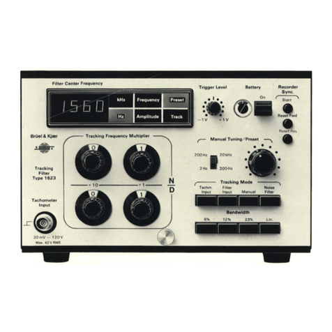
BRUEL & KJAER 1618 User manual

Artisan Technology Group is your source for quality
new and certied-used/pre-owned equipment
• FAST SHIPPING AND
DELIVERY
• TENS OF THOUSANDS OF
IN-STOCK ITEMS
• EQUIPMENT DEMOS
• HUNDREDS OF
MANUFACTURERS
SUPPORTED
• LEASING/MONTHLY
RENTALS
• ITAR CERTIFIED
SECURE ASSET SOLUTIONS
SERVICE CENTER REPAIRS
Experienced engineers and technicians on staff
at our full-service, in-house repair center
WE BUY USED EQUIPMENT
Sell your excess, underutilized, and idle used equipment
We also offer credit for buy-backs and trade-ins
www.artisantg.com/WeBuyEquipment
REMOTE INSPECTION
Remotely inspect equipment before purchasing with
our interactive website at www.instraview.com
LOOKING FOR MORE INFORMATION?
Visit us on the web at www.artisantg.com for more
information on price quotations, drivers, technical
specications, manuals, and documentation
Contact us: (888) 88-SOURCE | sales@artisantg.com | www.artisantg.com
SM
View
Instra

BAND PASS FILTER
TYPE 1618
Valid from serial no. 725507
Revision April 1 979

4
This apparatus has been designed and tested according to Class II of IEC Publication
348, Safety Requirements for Electronic Measuring Apparatus, and has been supplied in
safe condition. The present instruction manual contains information and warnings which
should be followed by the user to ensure safe operation and to retain the apparatus in
safe condition.

CONTENTS
1. INTRODUCTION AND SPECIFICATIONS (PRODUCT DATA) 1
2. CONTROLS 9
2.1. FRONT PANEL 9
2.2. REAR PANEL 10
3. OPERATION 12
3.1. PRELIMINARY ADJUSTMENTS 12
Selection of Mains Voltage 12
Mains Fuse Checks and Replacement 12
Mains Connections 12
Grounding Considerations 12
3.2. USE WITH MEASURING AMPLIFIER 13
3.3. USE WITH SOUND LEVEL AND VIBRATION METERS 14
4. RECORDING OF FREQUENCY ANALYSES 16
4.1. USE WITH LEVEL RECORDERS TYPE 2306 AND 2309 16
4.2. USE WITH LEVEL RECORDER TYPE 2307 19
5. SPECIAL CONSIDERATIONS IN FREQUENCY ANALYSIS 23
5.1. FILTER DEFINITIONS 23
TheIdeal Filter 23
Bandwidth 23
Octaves and Third Octave 24
Specified Filter Frequencies 24
5.2. RMS MEASUREMENT AND STATISTICAL ACCURACY 25
5.3. PRACTICAL ANALYSIS OF STATIONARY SIGNALS 26
AveragingTime 26
DCor AC Recording 27
Writing Speed 27
PaperSpeed 28
6. SERVICE AND REPAIR 29

types 1617 and 1618
Third-Octave and
Octave Band Pass Filters
GENERAL FEATURES:
•41 third-octave filter
bands, centre frequencies
2 Hz to 20 kHz
•41 overlapping octave
filter bands, centre
frequencies 2 Hz to 20 kHz
•Third-octave and octave
filters in accordance with
IEC 225 - 1966, DIN
45 651 and 45 652, and
ANSI S1.11-1966
•Digital display of selected
centre frequency and
bandwidth
•Built-in A-weighting
network
•Electronic control of filter
switching
•Manual or Level Recorder
controlled filter scanning
•Selectable scan start
position to save time,
eliminates low frequencies
when required
•Input overload warning
circuit
•Floating or grounded
signal input
11111 1 6 1 8
ADDITIONAL FEATURES
TYPE 1617:
•9 third-octave filter bands,
centre frequencies 25 kHz
to 160 kHz
•Built-in B, C, D-weighting
networks
•Comprehensive connection
facilities for use with other
instruments
•Operation of front panel
controls via built-in IEC
Interface
•Selection and control of
averaging time program for
the measuring instrument
INN
USES:
(With suitable Measuring
Amplifiers)
•Third-octave and octave
frequency analysis of
sound and vibration
•Measurement of frequency
response
•Measurement of sound
transmission loss
im Measurement of vibration
isolation
• Testing acoustic materials
•Recording of spectrograms
with constant confidence
level (1617)
19-029

The Third-Octave and Octave
Band Pass Filters Type 1617 and
Type 1618 are key links in any in-
strumentation chain for measure-
ment and recording of the fre-
quency spectra of sound, vibration,
and electro-acoustic signals. Sev-
eral novel features have been in-
corporated, including electronic fil-
ter switching and digital indication
of the selected filter, The Band Pass
Filter Type 1618 is the basic instru-
ment, while the Type 1617 com-
bines an extended frequency range
with comprehensive control and syn-
chronisation facilities for use with
other instruments.
The Type 1618 has filter band
centre frequencies from • 2 Hz to
20 kHz that can be divided into 41
third-octave bands, or 41 overlap-
ping octave bands covering the 14
octave frequency range. It has a
built-in A-weighting network, and
there is indication given when the
level of the signal being analyzed
overloads the input section. The
Band Pass Filter has provision for fil-
ter scanning controlled by B & K Le-
vel Recorders.
The Type 1617 has filter band
centre frequencies from 2 Hz to
160 kHz that can be divided into 50
third-octave bands. It has 41 over-
lapping octave bands covering 14
octaves from 2 Hz to 20 kHz. In addi-
tion to the A-weighting, it includes
B, C, and D-weighting networks,
and there is also an input overload
indicator lamp. Filter scanning can
be controlled by a Level Recorder,
and there is a built-in interface to
the proposed IEC Digital Bus Stand-
ard to permit direct control by other
instruments and systems using this
standard. A DC ramp output can
control the X-axis of an X-Y Recor-
der, and a control circuit is included
to select averaging time programs
for use by the measuring instru-
ment.
Both Band Pass Filters will gener-
ally be used with one of the Measur-
ing Amplifiers Type 2606, Type
2607, or Type 2608, but other in-
struments such as the Frequency
Analyzer Type 2120 and the Hetero-
dyne Analyzer Type 2010 can be
employed. Connected to a B & K
Condenser Microphone, these mea-
suring instruments all form a sound
measurement system that satisfies
IEC 179 for precision sound level
meters, while Type 2606, Type
2607, and Type 2120 satisfy IEC
179A for Impulse measurement.
All three Measuring Amplifiers
can be employed with either Band
Pass Filter, so that selection of
which Measuring Amplifier to use
will largely depend on the particular
measurement application. Table 1
shows the various combinations
available, together with brief specifi-
cations, and the type of measure-
ment and analysis possible. The ba-
sic system of Type 1618 and Type
2608 is for RMS measurement in
the audio frequency range, with fil-
ter selection by Level Recorder. Opti-
mum utilisation of all measuring
modes and control possibilities is ob-
tained with a combination of Type
1617 and Type 2607, which gives
the ability to measure and analyze
in the frequency range from 2 Hz to
160 kHz, obtaining RMS and Peak
values from all commonly encoun-
tered random, quasi-random, peri-
odic, and complex waveforms. This
combination can be used together
with an Recorder such as Type
2308.
Measuring Amplifiers Band Pass Filter Type 1618 Bend Pass Filter Type 1617
General:
Freq. Range: 2 Hz — 200 kHz
Dyn. Range: 10pV — 300V
Fast and Slow averaging
Input overload warning
General:
Freq. Range: 1.4 Hz — 22 kHz
41 third-oct. bands
41 overlapping octave bands
A-weighting filter
General:
Freq. Range. 1,4 Hz — 180 kHz
50 third-oct. bands
41 overlapping octave bands
A, B. C, D-weighting filters
Averaging time programs
Control via built-in IEC interface
DC ramp for X-Y Recorder control
Type 2608 and 2121
RMS measurement
Crest factors up to 5
AC output to Level Recorders
A-weighting network
RMS measurement
20 Hz — 22 kHz
(Audio frequencies)
20 Hz— 180 kHz
Manual or remote control of filter scanning
Digital bus control of filter
scanning
Measurements can be made at lower frequencies if the
averaging ability of a Level Recorder 2307 is used
Type 2606
RMS and Peak measurement
Impulse and Hold modes
Crest factors up to 40
AC or DC outputs to Recorders
A, 8, C, D-weighting networks
Range settings shown on
meter scale
Comprehensive RMS measurement at high crest factors
20 Hz— 22 kHz
(Audio frequencies)
20Hz — 180 kHz
Manual or remote control of filter scanning
Digital bus control of filter
scanning
Measurement in Peak or Impulse Modes
1,4 Hz— 22 kHz 1.4 Hz— 180 kHz
RMS measurements can be made at lower frequencies if the
averaging ability of a Level Recorder 2307 is used
Type 2010 IRMS only),
2607, & 2120
RMS and Peak measurement
Impulse and Hold modes
Crest factors up to 5
AC or DC outputs to Recorders
50 dB logarithmic DC output
proportional to RMS Level
A, B, C, D-weighting networks
Range settings shown on meter'
scale
Measurement of RMS and Peak values of all commonly encount-
ered random, quasi-random, periodic. and complex waveforms
1.4Hz — 22 kHz 1,4 Hz— 180 kHz
Manual or remote control of filter scanning
Manual control of averaging time for 2607, 2120, or 2010
Digital bus control of filter
scanning and averaging times
for 2607 and 2120
This combination gives optimum
use of all measurement and
control facilities, including
X-Y recording (not 20101
Table 1. Band Pass Filter and Measuring Amplifier Combinations
2

Description
Both Band Pass Filters are de-
signed to operate on the signals ob-
tained from the External Filter termi-
nals of the Measuring Amplifiers,
but any input signal of approxi-
mately 1V RMS with a crest factor
less than 5 can be accepted (the
higher crest factor capability of the
Type 2606 can be used at lower sig-
nal levels). Input and output are via
coaxial B & K sockets on the front
panel, paralled by BNC terminals on
the rear.
Filter I Filter II
Centre , Centre
Frequency Frequency
Hz Hz
1/3 Octave
Bandwidth
at 3,7 dB
Hz Approx.
2
3,15
5
8
12,5
20
31.5
50
80
126
200
315
500
BOO
1250
2000
3150
5000
8000
12500
20000
25000
31500
40000
50000
63000
80000
100000
125000
160000
2.5
4
6,3
10
16
25
40
63
100
160
250
400
630
1000
1600
2500
4000
6300
10000
16000
Additional
1/3-octave
filters
in 1617
0,46
0,50
0.73
0,92
1.16
1,45
1,83
2,30
2,90
3,70
4,60
5,8
7,3
9.2
11,6
14,5
16,3
23
29
37
46
58
73
92
116
145
183
230
290
370
460
580
730
920
1160
1450
1830
2300
2900
3700
4600
5800
7300
9200
11600
14500
18300
23000
29000
37000
Table 2. Filter centre frequencies in pre•
(erred series. Heavy type denotes
preferred series for full-octaves
C) Input
Overload
Warning
Input
Amplifier
8
2Hz -
20 kHz
1/1-1/3 oct
Filter I
is)
0I
Low Pass
ss./C
2,5 Hz -
16 kHz
1/1-1/3 oct
Filter II
4..425 kHz
4-131,5 kHz/
4:40 kHz
Front
Paver
Controls
:50 kHz
:.:i!63 kHz-
480 kHz/
100 kHz
125 kHz
160 kHz
Filter':;;:.
Selector
Filter
Selector II
V
Digital
Controller
Amplifier
Low Pass
Filter
Output
Amplifier
Output
Interlace
....•• ,•
Digital
Averaging Time;::
,?.:•..,•••••
X-Y Recorder:.
Level Recorder
Control
76,0391
Fig.1. Block diagram of the Band Pass Filters Type 1617 and Type 1618
Fig.1 is a block diagram valid for
both versions of Band Pass Filter,
where shaded areas represent fea-
tures found only in the Type 1617.
Third-Octave Band Pass Filters
The active Filter sections consist
of a matched pair of variable fre-
quency six-pole Butterworth filters
which can be electronically
switched to yield third-octave or full-
octave bandwidths. Between them
the two Filters cover the frequency
range from 2 Hz to 20 kHz centre
frequencies, with each Filter being
switched to alternate third-octave
centre frequencies in the preferred
series (see Table 2)
In the Band Pass Filter Type
1617 there is an additional set of
third-octave Filters with centre fre-
quencies between 25 kHz and
160 kHz, to extend the high fre-
quency range of the instrument.
these instruments fulfil the require-
ments of IEC 225 — 1966, DIN
45652, and ANSI S1.11-1966
Class III, which are the most rigor-
EC
Typical 8 & K
1/3 Octave Filter
\ ANSI Class III
,f0IN 45652)
0,2 0,5 2 4
Frequency relative to centre frequency f/fm „0,03j
dividual third-octave Filters used in Fig,2. Typical third-octave filter response
The filter characteristics of the in-
3

ous standards applying to third-
octave filters. The response curve for
atypical third-octave filter is shown
in Fig.2, and the top of the curve in
the enlarged view in Fig 3. The IEC,
DIN, and ANSI limitations are also
indicated in both Figures. Peak-to-
valley ripple in the pass band is less
than 0,5 dB with attenuation within
f: 0,5dB. Attenuation of frequencies
outside 5x and 1/5 of the band
centre frequency is better than
75 dB.
Octave Band Pass Filters
Octave Filters are formed in both
Band Pass Filters by electronically
altering the components and charac-
teristics of the Filter circuits. This ar-
rangement gives a flat crest to the
characteristic curve, and low peak-
to-valley ripple. The octave Filters
cover the frequency range from
2Hz to 20 kHz centre frequencies,
selectable at third-octaves in the
preferred series. There is no provi-
sion for connection of full-octave fil-
ters at higher frequencies in either
Filter Set.
All octave Filters contained in the
Type 1617 and Type 1618 conform
to IEC 225 — 1966. DIN 45651,
and ANSI S1.11-1966 Class II,
which are the strictest standards for
octave filters. Fig.4 shows the top
of a typical octave filter characteris-
tic, attenuation outside 8x and 1/8
of the band centre frequency is bet-
ter than 60dB. Peak-to-valley ripple
is less than 0,5dB, while attenua-
tion in the pass band is within
±0,5 dB.
The total integrated random
(white) noise power passed by the
practical octave and third-octave Fil-
5
0
-10
-15
-20
-25
-30
00
O
..
-2
0
4
6
8
10
12
14
16
18
20
22
0.4
Max. Ripple
(peak-to-valley)
0,5 dB
IEC
(DIN 45 652)
ANSI Class III
Typical B & K
1/3 Octave
Filter
0,6 0,8 9'0 1,4 1,8 2,5
0,5 0,7 0 9 ,2 1,6 2,0
Frequency relative to centre frequency fillm
110124/I
Fig.3. Top of a third-octave filter characteris-
tic
ters in the Type 1617 and Type
1618 is equal to that which would
be passed by an ideal octave or
third-octave filter.
Weighting Networks
In addition to the Linear re-
sponse, and A-weighting network in-
cluded in the Type 1618, the Type
1617 contains B- and C-weighting
networks, plus the D-weighting net-
work specified in IEC 537 for meas-
urement of aircraft noise. The fre-
quency responses of the four
weighting networks are shown in
Fig.5. The Figure also indicates the
Linear range 1 Hz to 200 kHz obtain-
able from the Type 1617, and the
Linear range 1 Hz to 40 kHz from
the Type 1618.
Filter Selection and
Scanning Ranges
Filter switching is accomplished
electronically by FET switches in
the Filter Selectors that are regu-
CO -2
go
12
19
20
22 04 05 06 07 cia 00 10
Max Ripple
(peak-to-valley)
0,5 dB
IEC
ANSI
Class II
Typical
AB & K
octave
Filter
12 IA lb 18 20 25
Frequency relative to centre frequency f/fm
7101250
Fig.4. Top of a typical octave filter charac-
teristic
lated by the Digital Controller acting
on instructions from internal or re-
mote control settings. Bandwidth of
the Filter in use is selected by the
three position Selectivity switch, giv-
ing a choice of third-octave band-
width scanning in third-octave
steps, octave bandwidth scanning
in third-octave steps (with adjacent
bands partially overlapping), or oc-
tave bandwidth scanning in full-
octave steps.
Manual selection of any particular
Filter band is made by turning the
Manual Filter Selector control to the
required position. On the Band Pass
Filter Type 1618 the Manual Filter
Selector has a scale graduated in
third-octave centre frequencies
from 2 Hz to 20 kHz, plus the two
positions "A-weighting" and "Lin-
ear". There are two measuring
ranges on the Band Pass Filter Type
1617, selected by the Range
switch, and hence two frequency
Typical Frequency Characteristics .88181111....
MI I 11■
Linear 1 Hz 200 kHz
Ailehl MI•11111 MIS
to Ilk. Linear 1 Hz to 200 kHz ME
1111111111111.1111191111•PPA
8+`��,111e 11618) 11
-rnmirnor 11115111k
0.2 05 210 100 200 500 1 k 2k 5k 10 k20k.
Fig.5. Weighting networks and Linear functions
50 k 100 k 200 k 500 k
'0 os
4

scales. One covers the full fre-
quency range with graduations in
third-octaves with centre frequen-
cies from 2 Hz to 160 kHz. The
other range covers third-octave cen-
tre frequencies between 2 Hz and
40 kHz, and includes A-, B-, C-, 0-
weighting, and a Linear position.
Both models have a "Linear" mode
available on the Range switch,
which permits a Linear output to be
obtained at any point in a scan,
without moving the Manual Filter
Selector.
The centre frequency of the se-
lected Filter band is indicated on a
half-inch digital display that also
shows whether the Filter is function-
ing as a third-octave or as an oc-
tave filter, or whether a weighting
network has been selected.
Filter Scanning
In addition to its control of the Fil-
ter switching as directed by the
Manual Filter Selector, the Digital
Controller can operate the Filter
scan on the commands of an exter-
nal source. Control by a Level Recor-
der Type 2306, Type 2307 or Type
2309 is possible with both Band
Pass Filters. On the Type 1617 con-
trol can also be exercised via the
built-in IEC Interface, or an X-Y Re-
corder such as Type 2308 can be
operated in synchronism with Filter
scanning (possible with Type 2607
Measuring Amplifier or equivalent).
Selection of manual or recorder
control is made by the Filter Control
Mode Manual/Recorder switch,
while the Stop/Run switch enables
the Recorder in use to be controlled
from the Band Pass Filter. This con-
trol facility is blocked when "Man-
ual" is selected, or when the Type
1617 is being controlled via the In-
terface.
When operating in any remote
control mode, the progress of the
scan can be followed on the Digital
Display, as the Manual Filter Selec-
tor does not rotate during an auto-
matic scan. The Filter frequency
sweep always starts from the band
in which the Manual Filter Selector
is standing, it sweeps through the
selected range, and being internally
actuated, it returns instantly to its
starting point. This saves analysis
time when low frequencies (with
correspondingly long averaging
times) will not be required while
operating the Type 1617 with an X-
YRecorder, or under digital control
via the Interface bus. Similarly,
when recording sound on a Level
Recorder, unwanted low frequency
bands can be excluded from the
trace to yield a clear audio fre-
quency spectrogram.
1618
oil
Oro. .00.." *0,4 3 23.13.- • 30*.
Connections for synchronisation
with a Level Recorder Type 2307 is
made via a 7-pin DIN socket on the
rear panel (see Fig.6). Connection
to a Level Recorder Type 2306 is
achieved via an 8-pin DIN socket,
which with the Type 1617 is also
used for X-Y recording.
11111111111111111111111111111111111111
rzail Ic,
EZ3 • •
III irazai 111111
MIL
I•
cfm,
11111111iiiinniiiiiim11111m11111
Fig.6. Rear panels of the Band Pass Filters
,
°
Fast Random/1 f MGM /
•El
eto
12
Frequency
ac
M.;
C.:22.301 Aar 2002
Fig.7. Conditions where longer averaging times are required for high frequency signals. The
lower curve was made with too short averaging time, while for the upper curve, averag•
ing was correct
5

Averaging Time Control
This ability, allows the Type 1617
to vary the averaging time of the
Measuring Amplifier Type 2607 or
the Narrow Band Analyzer Type
2120 during the course of the fre-
quency scan. The advantage is that
the averaging time can be kept as
short as possible to maintain an ac-
ceptable analysis time, while being
long enough at lower frequencies to
achieve optimum measuring accu-
racy, i.e. to maintain a good confi-
dence level. The best analysis condi-
tions are obtained when the product
of bandwidth B (in Hz) and averag-
ing time T (in s) is held constant
throughout the scan. Therefore the
Type 1617 is equipped with averag-
ing time programs which can be se-
lected according to test conditions
to maintain the BT product as near
constant as possible and give a con-
stant confidence level.
At higher frequencies, if a con-
stant BT product is to be main-
tained, the averaging time becomes
so short that the writing speed of
the Recorder will be the practical li-
mitation on the speed of the analy-
sis. Therefore the shortest averag-
ing time that can be selected by the
programs in the Type 1617 is
0,1 s. However, some high fre-
quency signals like the noise or vi-
bration from a slowly rotating ma-
chine may have a low repetition fre-
quency that causes low frequency
modulation as shown in Fig.7,
where 0,1 s averaging time is too
short. To allow satisfactory averag-
ing times to be selected for this
type of signal, a choice of three min-
imum times (0,1 s, 1,0 s, and 10 s)
is provided on the Type 1617. Fig.8
is a chart indicating the averaging
times and change-over frequencies
in the nine programs available, to-
gether with the minimum and maxi-
mum averaging times.
When operating with variable av-
eraging times, selection of the re-
quired program is made with the
two Averaging Control switches on
the front panel, and the Recorder
Averaging Time switch on the rear
panel must also be set to "Variable
Averaging Time". Table 3 shows
how the programs can be selected
by suitable combination of the Pro-
gram and Minimum Time switch po-
sitions. The programs are obtained
Averaging Time
(s)
100
30 -
10
3
1
0,3
0,1
C,F,J Slow Random
B,E,H Fast
Random
1;1
A,D Sine
1
its
A
G,H,J
1,0 5
B
D,E,F
0,1 s
A,B,C
510 20 50 100 200 500 1 k 2k 5k 10k 20k
Switchover Frequency tHz1
Fig.8. Averaging times and changeover frequencies
Minimum Av. Time(s) 0.1 ,o 10
Slow Random
Fast Random
Sine
E
(G)
Table 3. Selection of the required averaging
time program
via the 15 lead AVERAGING TIME
CONTROL socket on the rear panel.
With a Level Recorder, automatic
averaging time control functions as
follows. The scan starts with the Re-
corder being held for a period of
five times the programmed averag-
ing time for the band, during which
time the pen comes up to the cor-
rectly averaged level. Then a long
averaging time is selected that
keeps the output constant while the
Recorder draws the trace by advan-
cing the paper at high speed to the
next frequency band. The Filter
steps to the next band in the se-
quence, and the programmed aver-
aging time is selected, after which
the Recorder hold period begins
again.
161041
Using an X-Y Recorder, where
the X-axis is controlled by the DC
ramp output from the Type 1617,
the Recorder pauses for five times
the averaging time, and then takes
eight steps through each third-
octave band.
Figs.9, 10, and 11 show analysis
of the same input signal recorded
using three different methods to il-
lustrate their relative merits.
Built-in IEC Interface
The Type 1617 is fully program-
mable via a built-in interface that sat-
isfies the requirements of the pro-
posed IEC Standard Digital Interface
for Programmable Instrumentation.
This permits the filter frequency
bandwidths, and averaging time to
be varied in an arbitary sequence,
and recording initiated to suit any
particular measuring program. It
also permits on-line changes to be
made to accomodate new events as
they occur.
W130iel IS Naar B,uel6 6per eruel 6 Km,
Itpinocioop000ciouoD000n000rioacr000000naocici0000nou000cc
BrOel&Kjaar Polentionanel Ra•04:—W-01) Recur.. ilai-Lowee Lin Greg _Vim, 611, Speed.- 119.—carn,sec Paper eel -nlark sec
Afro- - - 1075
Icop..h., 60 2
c111 dB
Ali 401' 40 20
Meseunna Obj
Fined
Acerag.ng-
7,n. —3° t5
1/3 XLDVE— -
Time used 250
-24) 30
25 Hz - 40 kHz, --
0. A, 0. C, Lin
....•....••
OP 1124
50
40
10 20 = 60 100
Mull ply Frequency Seale by
16.
200 SOO 1000 2000 6000 0000 20000 400000 5 B C
2roL vol
dB
512"2112 A 15 C 765042
Fig.9 Frequency analysis with Level Recorder and fixed averaging time
6

The following interface functions
are available on the Type 1 61 7:
Acceptor Handshake (AH1)
Listener Function (L2)
Remote Local Function (RL2)
Parallel Poll Function (PP2)
Busy is indicated via NRFD (not
ready for data) hold method when
the Band Pass Filter is feeding a Re-
corder.
AListen Address switch on t.
rear panel allows the instrument
Listener address to be set for use
with remote digital control. There is
a PPR Selector for setting the Paral-
lel Poll Response, used here to re-
port whether there has been an
overload in the Input Amplifier
since the previous interrogation.
This is used to assess the validity of
the levels measured in the filter
bands.
Connection to the digital bus is
made via the 25-lead plug on the
rear panel of the instrument.
Operation with other
instruments
Fig.1 2 shows the connection pos-
sibilities with other Bruel & in-
struments, including the cables re-
quired.
The Band Pass Filters can also be
employed as external filters for
B& K Sound Level Meters and Vi-
bration Meters.
0::11:1071:
enrol e Niir
oID a 0 o o un000 o Dacca lb c.ie"o. 03. .lco:a'::0000. 00i71.0 0 O.
81'0018i Kim Potentiom411t Ranee: 46 Aectobar. 13-1...,or Um. top .He . Sp444 nsm/mc Parsee Speed 10 mm. sac.
co......en 50 2
de ..
42050
141442.onn0 Obi
V44able-_
Ar1,40A5
Time - • In
ii
1/3 *cu.— F i— .
Fur ninsonve, s..... EFI
25 Time usedHz - 40 kH ..
90 si
210 im
—Hi
DA (a C 1..n ,
.
20' IIIMIll
'
&MP
11t4c_
.0.04
10 20 111 50 100
1CIP 1124
;
M.MIply Frequamy Scala by
r--
200 SOO 1000
Zero Leve1
2000 6000
.60
C
ab
30
10000 20000 400000 A e C 0
1612/2112 A 5 C 76 04
Fig.10. Frequency analysis with Level Recorder and variable averaging times
Variable Averaging Time
1/3 octave
Fast Random/0,1 s
25 — 40 kHz— D A IC Lin
Time Used 180 s
mm nesgitlf 1 e.kader .
Fig.1 1. Frequency analysis with X-Y Recorder and variable averaging times
AG, 541
—
dl
_IV;
2-.C2 I
gct
.1
FI
CI
141
;I
<I
Input
Input
1..vd1 • ..;"_
Control Cable AO 0034
Band Pass Filter 1617
o•_
Ba▪nd Pass Filter 1618
\Digital Connection
to IEC Interface bus
AO 0129
Measuring Amplifier 260▪8
;•
Input
•41
2306 with 8 pin Control
Socket: AO 0034
2306 with 7 • pin Control
Socket: AO 0182
1to
1Q
-I
I•E•
I
Ig
Ice
Signal Output. B& K to BNC Connect on Cable AO 0064 AO 0064
777
Level Recorder 2306
Signal output, B & K Connection Cable
-_ AO 0014
Measuring Amplifier 2606
•-I- :04-If 7§1:4 '•
•___,...M.'
w—
Measuring Amplifier 2607 Level Recorder 2307
2308
KY Recorder
Tap e Recorder 7003 or 7004
761040
Fig.1 2. Connection possibilities with other 13 &K instrumentation
7

Specifications 1617 and 1618
Band Pass Filters:
In accordance with IEC 225 1966. DIN
45651 and 45652, and ANSI S1.11-
1966 best classes
The total integrated random white noise
power passed by the filters in these in-
struments is equal to that which would
be passed by an ideal filter
Centre Frequencies 1617:
1/3 oct: 2 Hz to 160 kHz (50 bands)
1/1 oct: 2Hz to 20 kHz (41 overlapping
bands at 1/3 octave intervals covering
14 octaves)
Centre Frequencies 1618:
1/3 oct: 2Hz to 20 kHz (41 bands)
1/1 oct: 2Hz to 20 kHz (41 overlapping
bands at 1/3 octave intervals covering
14 octaves▶
Attenuation Outside Pass Band:
1/3 oct: >75 dB at 5. and 1/5 cen-
tre frequency
1/1 oct: > 60 dB at 8. and 1/8 centre
frequency
Attenuation at Centre Frequency (fm):
1/3 oct and 1/1 oct: 0 c18 ± 0,5 dB
Maximum Peak-to-Valley Ripple:
1/3 oct: 0.5dB
1/1 oct: 0.5dB
Overall Selective Frequency Range:
1617: 1,4Hz to 180 kHz
1618: 1,4Hz to 22 kHz
Linear Pass Band (Available from Range
switch or Manual Filter Selector):
1617:
1,6Hz to 160 kHz attenuation is 0d8
±0,3 dB
1Hz to 200 kHz attenuation is 0dB
±0,5d)3
1618:
1,6 Hz to 31,5 kHz attenuation is 0dB
±0,3 dB
1Hz to 40 kHz attenuation is 0dB
±0,5 dB
Filter Selection:
Type 1617:
2Hz to 160 kHz
2Hz to 40 kHz, D. A, B, C, Linear
Type 1618:
2 Hz to 20 kHz, A, Linear
Switching control:
Manual: from -Manual Filter Selector"
Automatic: from a Level Recorder
Automatic: to control an X-Y Recorder
(1617 only)
(When scanning octave filters, either full-
octave or third-octave stepping can be se-
lected)
Automatic: via the IEC interface bus
(1617 only)
Weighting Networks:
Curves A, B. and C are in accordance
with IEC 179 for precision sound level
meters (1618 has A-weighting only)
Curve D is in accordance with IEC 537
Averaging Time Programmes (1617 only):
Used with Measuring Amplifiers that fea-
ture remote controlled averaging times
(Type 2607)
Programmes Available:
See Table 3 and Fig,8
Input:
Via B & K coaxial socket on front panel,
paralleled by 8NC socket on rear
Impedance:
1M011 100 pr
Voltage:
1V RMS nominal
5 V peak maximum
5,6V (± 0,3 V) overload warning lamp
lights
Distortion:
Band Pass Filters:
<0,1% with 1V signal level
<0.3% with 3,6 V signal level
Linear Range:
<0,1% with 1V signal level
<0,3% with 3,6V signal level
Noise:
<150pV (typ. 100) Band Pass Filters
<110pV (typ. 80) A, 8, and C-weighting
networks
<250pV (typ. 180) D-weighting net-
work
<100pV (typ 80) Linear range
Output:
Via 8 & K coaxial socket on front panel,
paralleled by BNC socket on rear
Impedance:
<500
Minimum Load Impedance:
5 MI ll 1 nF for less than ± 0,2% reading
error
DC Ramp Output (1617 only):
Used for controlling the X-axis of an X-Y
Recorder
0 V at the starting frequency
0,208 V per 1/3 octave increase rate
10,4 V maximum output
Load impedance > 10 kr1
Digital Bus Interface (1617 only):
Conforms with the proposed IEC Stand-
ard Digital interface for Programmable In-
strumentation
Contains the following functions
Acceptor Handshake (AH 1)
Listener Function (L2)
Remote Local Function (RL2)
Parallel Poll Function (PP2)
Environmental Conditions:
Operating Temperature Range:
5°C to 40°C (41°F to 104°F)
Storage Temperature:
—25°C to + 70°C (-13°F to + 158°F)
Permitted Humidity Range:
The outputs from the instruments are ac-
curate between 0 and 90% relative hu-
midity. provided there is no condensation
Power Requirements:
100, 115, 127, 200, 220. 240 V AC
±10%
50 to 400 Hz
1617: approx. 37 VA
1618: approx. 30 VA
Comply with IEC 348 Class II
Cabinet:
Supplied as model A (light-weight metal
cabinet), El (model A in a mahogany cab-
inet). or C (as A but with flanges for
standard 19" rack mounting)
Dimensions:
Height: 133 mm (5,25 in)
Width: 430 mm (16,9 in)
Depth: 200 mm (7,9 in)
Weight:
1617: 6,5 kg (14,31b)
1618: 6,3 kg (13.91b)
Accessories Included:
1AN 0010 Power cable
2JB 0002 Banana plug
2JP 0035 BNC plug
2JP 0101 B & K coaxial plug
1JP 0703 7-pin DIN plug
1JP 0802 8-pin DIN plug
2VF 0012 Fuse
Accessories Available:
See Fig 12

2. CONTROLS
2.1. FRONT PANEL
Manual niter Selector
Selected Filter
POWER ON:
770366
Input Selectivity Range Filter Control Mode Output
Ftg.2.1. Front panel controls of the Type 1618
Power On
Power is on with the switch in the up position. Warm-up time is ap-
proximately five seconds.
MANUAL FILTER SELECTOR: A rotary switch that selects the filters and weighting networks when
operating in the "Manual" control mode. The filter selected is shown
on the frequency scale.
SELECTED FILTER: A digital display that shows the centre frequency of the selected filter.
The display also indicates the bandwidth chosen, and whether a linear
or weighted response has been selected.
INPUT:
SELECTIVITY:
Standard B & K coaxial socket, fitting JP 0101 Plugs, paralleled by a
BNC socket on the rear panel. There is an input "Overload" lamp, and
aseparate ground terminal. The maximum input voltage is 5V, and
the impedance is 1 MO in parallel with 100 pF.
Athree-position switch that selects the bandwidth of the filters, and
the centre frequency step length for full-octave scanning. Functions
are as follows:
Upper position: third-octave bandwidth with scanning in third-octave
steps.
Middle position: full-octave bandwidth with scanning in third-octave
steps, with overlapping.
9

Lower position: full-octave bandwidth with automatic scanning in full-
octave steps.
RANGE: Atwo-position switch to select the narrow band range, or "Linear",
for both manual and remote controlled operation. Functions are as fol-
lows:
Upper position: "Linear" range from 1 Hz to 50 kHz, independent of
the position of the MANUAL FILTER SELECTOR.
Lower position: "2 Hz to 20 kHz A-Lin.", filters are selected automati-
cally, or by the MANUAL FILTER SELECTOR.
FILTER CONTROL MODE: Two switches that control how the filters are selected, plus two LED in-
dicators,
OUTPUT:
2.2. REAR PANEL
Fuse
The left-hand switch can select "Manual" so that the filters are
chosen by the MANUAL FILTER SELECTOR or it can select "Recorder"
mode allowing filter selection to be made by external control.
The right-hand switch enables the Recorder in use to be controlled
from the Band Pass Filter. This facility is blocked when "Manual" has
been selected. Two LEDs light to indicate whether "Stop" or "Run" is
selected.
Standard B & K coaxial socket, fitting JP 0101 Plugs, paralleled by a
BNC socket on the rear panel. There is a separate ground terminal. Im-
pedance less than 200, minimum load impedance 5 kf) in parallel
with 1 nF.
Output
111.1171."-I. 11111111111111111111111111111111111111
dine Voltage
t410 ••
Chassis li
Signal Ground
Mains Input -11111111111111111111111111111111111111
Recorder
Control 1
Fig.2.2. Rear panel connections of the Type 1618
Input
Recorder
Control II
770367/1
CHASSIS-SIGNAL-GROUND: A pair of clamping terminals with a shorting strap, permiting the signal
ground to be connected to the instrument chassis. See section 3.1.4.
LINE VOLTAGE: Voltage selector for operation of the 1618 from 100, 115, 127, 200,
220 and 240V (50 to 400 Hz) single phase, AC mains lines. To select
the correct voltage setting see section 3.1.
10

LINE INPUT.
FUSE:
OUTPUT:
INPUT:
RECORDER CONTROL I:
RECORDER CONTROL II:
Input for filter
shift pulses + 32
32 V
to seect
Automatic Stop
—0 V
Not used
Input socket accepting the Power Cable AN 0020 provided, for connec-
tion of an AC mains supply. Before connecting the apparatus to a sup-
ply, the mains voltage setting and fuse checks given in section 3.1
should be carried out.
Fuse holder containing a 200 mA slow blow fuse for operation from
200 to 240V AC mains lines. For 100 to 127V operation, a 400 mA
slow blow fuse should be fitted. See section 3.1.
BNC socket in parallel with front panel output socket.
BNC socket in parallel with front panel input socket.
7-pin DIN socket for remote switching of the filters by a Level Recorder
Type 2307. For connections see Fig.2.3.
8-pin DIN socket for remote switching of the filters by a Level Recorder
Type 2306 or 2309. For connections see Fig.2.4.
+32 V DC from
Recorder (indicates)
Recorder on)
+32 V to
stop Recorder
immediately
+32 V to
select pen lift n0174
Not used
Filter shift
pulses
0 V to select
Automatic Stop
0V to stop
Recorder immediately
Not used
+6 V from
Level Recorder
(indicates recorder
on)
0 V for
pen down 1701102
Fig.2.3. RECORDER CONTROL I viewed from Fig 2.4. RECORDER CONTROL II viewed from
outside the socket outside the socket
Z\ Warning: The 1618 is designed to be operated with its signal ground lines and chassis
always at earth potential. Never let the signal ground terminals, socket screens or chas-
sis float at any other potential, as this will impair the operating safety of the 1 618 and
may damage the instrument.
11

3. OPERATION
3.1. PRELIMINARY ADJUSTMENTS
Before connecting a mains supply the following checks and adjustments should be car-
ried out to ensure safe operation of the apparatus.
3.1.1. Selection of Mains Voltage
The 1618 may be powered from a 100, 115, 127, 200, 220 or 240 V (50 to 400 Hz)
AC mains supply. To select the correct mains voltage setting, use a small coin or wide
blade screwdriver to turn the LINE VOLTAGE selector on the rear panel so that the ap-
propriate voltage indication on the selector faces the arrow marked on the panel.
3.1.2. Mains Fuse Check and Replacement
The mains fuse is contained in the fuse holder just beneath the LINE VOLTAGE selector.
To release the fuse use a screwdriver to turn the centre of the holder. For operation
from 100 to 1 27 V mains supplies the fuse should be an 400 mA slow blow (B & K No.
NF 0039), whilst for 200 to 240V supplies it should be a 200 mA slow blow (B & K No,
VF 001 2). Make sure that only fuses with the required rated current and of the specified
type are used for replacement. The use of mended fuses and the short-circuiting of fuse
holders shall be avoided.
3.1.3. Mains Connections
Once the mains voltage setting and fuse have been checked, the mains supply may be
connected to the LINE INPUT socket of the 1618 using the Power Cable AN 0020 pro-
vided. The LINE INPUT socket is not equipped with a chassis terminal for connection to
the protective ground contact of a mains socket outlet, as the high standard of protective
insulation of the 1 61 8 makes this unnecessary.
3.1.4. Grounding Considerations
When using the 1618 in complex measurement set-ups together with (other) mains op-
erated equipment, mains frequency pickup by ground loops may cause measurement er-
rors. To prevent this without prejudicing the operating safety of the measurement set-
up, the 1618 and other instruments with which it is used must be properly grounded.
To do this proceed as follows:
1. Connect the signal ground lines of all instruments together. This is done automati-
cally through the screens of the input and output cables.
12

If instruments equipped with a mains input chassis terminal are included in the set-
up, then ensure that all have their chassis connected to mains ground and that one
and only one of them has its chassis connected to signal ground.
Measuring Amplifier
2606, 2607, 2608
•• 1 Y- = • • •
Signal •it
*input
If instruments without a mains input chassis terminal are included in the set-up and
these are used free standing without their cabinets touching, then ensure that all of
them have their chassis connected to signal ground.
4. If instruments without a mains input chassis terminal are mounted in a metal instru-
mentation rack, together with one or more instruments that have a mains input
chassis terminal, then ensure that their chassis is disconnected from signal ground.
5. If instruments without a mains input chassis terminal are mounted in a metal instru-
mentation rack without an instrument having a mains input chassis terminal pres-
ent, then ensure that one and only one of them has its chassis connected to signal
ground.
6. Isolate the measurement transducer housing or disconnect the measurement system
signal ground from grounded measurement sources.
The signal ground and chassis of the Type 1618 are normally connected by the metal
strap between the ground terminals on the rear panel. If necessary the strap may be
removed to isolate the signal ground from chassis ground.
3.2. USE WITH MEASURING AMPLIFIER
The 1618 Band Pass Filter may be used with any Measuring Amplifier or Electronic
Voltmeter which is equipped with sockets for connection of an external filter. Suitable
types of Measuring Amplifier available from B & K are indicated in Fig.3.1. These have
an overall frequency range extending from 2 Hz up to 200 kHz and for sound, vibration
and voltage measurements may be connected with a wide range of measurement trans-
ducers and preamplifiers. The 1618 may be connected in series with, or in place of any
internal weighting network of the Measuring Amplifiers, forming a powerful measure-
ment set-up for octave and third octave frequency analysis of signals. The analyzed sig-
nal level can be read directly from built-in meter of the Measuring Amplifier. The basic
operating procedure is as described below.
t'•-• To Ext. Filter Input
To Ext. Filter Output • AO 0014/AO 0064
Band Pass Filter
1618
790099
Fig.3.1. B & K Measuring Amplifiers for use with Band Pass Filter
Type 1618
1. Carry out the necessary preliminary adjustments. See section 3.1 of this Instruction
Manual and the Instruction Manual for the particular Measuring Amplifier em-
ployed.
2. Connect the Filter Set and Measuring Amplifier as indicated in Fig.3.1.
3. On the Filter Set set the Power switch to "On" and the RANGE switch to "Lin".
13

4. With the Measuring Amplifier set to "Ext. Filter" calibrate it for sound, vibration or
voltage measurements as described in its Instruction Manual.
5. Turn the INPUT and OUTPUT SECTION ATTENUATOR knobs of the Measuring Ampli-
fier to their extreme clockwise position and disconnect the reference source.
6. Set Filter Set controls:
SELECTIVITY "Bandwidth" and "Record Step" as required
RANGE "2 Hz — 20 kHz — A — Lin"
FILTER CONTROL MODE "Manual" — "Stop"
MANUAL FILTER CONTROL Required octave, third octave, A weighting or Lin.
frequency band in which measurements are to be
taken.
7. Apply the signal to be measured to the appropriate INPUT socket on the Measuring
Amplifier and step the INPUT SECTION ATTENUATOR knob anti-clockwise to obtain
asuitable meter deflection without the INPUT OVERLOAD lamp flashing on the Mea-
suring Amplifier and Filter Set.
If the deflection is insufficient even when the INPUT SECTION ATTENUATOR is in its
extreme anticlockwise position, then step the OUTPUT SECTION ATTENUATOR knob
until a suitable deflection is obtained without overload.
8. The signal level within the selected frequency band can be read from the meter
where 0 dB or full scale corresponds to the value indicated by the range indicator
lamps and/or the INPUT and OUTPUT ATTENUATOR knob settings of the Instru-
ment. See Instruction Manual for appropriate Measuring Amplifier.
When reporting measured levels it should be stated which octave, third octave,
weighting or linear frequency band has been used.
9. Use the MANUAL FILTER SELECTOR to select other frequency bands for measure-
ments in the same way.
3.3. USE WITH SOUND LEVEL AND VIBRATION METERS
In
To Ext.-140!
Filter V
Precision Sound
Level Meters
2203, 2209
2210, 2218
AO 0007/AO 0116
Vibration Me er
2511 To Ext.
In Filter
Band Pass Filter
1618
0087/AO 0064
790200
Fig.3.2. Use of the 1618 Band Pass Filter with B & K Sound Level
and Vibration Meters
As indicated in Fig.3.2 the 1618 Band Pass Filter may be used for octave and third oc-
tave measurements with a portable Sound Level Meter or Vibration Meter. Operation is
14

similar to that described in the Instruction Manual for the particular Sound Level Meter
or Vibration Meter employed, except that for measurements its external filter mode
should be selected.
Note: For octave and third octave measurements with autoranging instruments, the man-
ual range control mode should be used.
15

4. RECORDING OF FREQUENCY ANALYSES
For fully automatic recording of octave and third octave analyses on frequency graduated
paper, the 1618 may be used with the portable Level Recorders Types 2306 and 2309
or the main operated Level Recorder Type 2307. Switching of the Band Pass Filter cen-
tre frequency is accomplished using the filter shift pulses generated by the Level Recor-
ders. Operation depends on the particular Level Recorder used and is described in the
following sections.
4.1. USE WITH LEVEL RECORDERS TYPES 2306 AND 2309
The instrument arrangement for automatic recording of octave and third octave analyses
with the 2306 and 2309 Level Recorders is shown in Fig.4.1. Also indicated are the ne-
cessary remote control cables for application of the Level Recorder filter shift pulses to
the RECORDER CONTROL II socket of the 1618 Band Pass Filter in the arrangement.
Recorder Control II
Band Pass Filter
1618
nput
AO 0014/AO 0064
V
Ext. Output
Filter
Input
Signal -•f
Measuring
Amplifier
2606, 2607, 2608
AQ 0182
L AO 0034-----_—J
Level Recorder
2306
with common
Remote Control-
Ext. Supply socket
Level Recorder
2306 (or 23091
with separate
Remote Control
Ext. Supply sockets
AO 0064 790201
Fig.4.1. Use of Level Recorders Types 2306 and 2309 for auto-
matic recording of octave and third octave analyses
With 2306 Level Recorders before serial no. 576700 a 3,3 k0 resistor must be sold-
ered to print board XC 1 062 (see Fig.4.2) to permit correct synchronization. For access
to XC 1062, disconnect all power from the Level Recorder and remove the four screws
under the black snap-on caps at each corner of the rear panel. XC 1062 is located be-
hind print boards XC 1059 and 1060 which may be released by unscrewing the two
screws and two spacers at the top of the respective boards. Modification should be per-
formed only by persons qualified in the service and maintenance of electronic measuring
instrumentation.
The procedure for recording an octave or third octave analysis is given below. This is
given with reference to the 2306, however, a similar procedure may be used with the
2309 Level Recorder.
16
This manual suits for next models
1
Table of contents
Other BRUEL & KJAER Water Filtration System manuals
Popular Water Filtration System manuals by other brands

velda
velda Floating Combi Filter 2500 User instructions

Anetsberger Brothers
Anetsberger Brothers GoldenFRY FFM-80 Specifications

CDL
CDL Hobby 81050 Operation procedures

3M
3M CS-340 Series Installation and instruction manual

Parker
Parker Racor 120R-RAC-01 Instruction

Flocell
Flocell XFM 900 Installation & operating manual