Sentinel JetFlush Rapid Owner's manual

1
JetFlush Rapid
EN Operating & Servicing Guidelines 3
FR Manuel d’utilisation et d’entretien 35
IT Guida per l’uso e la manutenzione 69
V1-02-15
Jetflush Rapid Guidelines (19-02-15).indd 1 19/02/2015 12:13

2Jetflush Rapid V1-02-15
Jetflush Rapid Guidelines (19-02-15).indd 2 19/02/2015 12:13

EN
3Jetflush Rapid V1-02-15
Main Contents
Section A – Introduction Page
Technical Data 4
Safety Precautions 5
Contents of each JetFlush Rapid Flushing Kit 6
Section B – Using the JetFlush Rapid pump for Power Flushing Page
Introduction 7
System Inspection and Preparation 7
Location and Connection of the JetFlush Rapid Pump 9
Initial Flushing Procedure (water only) 12
Chemical Flushing Procedure – Sentinel X800 Fast Acting Cleaner 15
Inhibitor and Corrosion Protection 17
Upon Completion 17
Quick Guide to Power Flushing 18
Radiator Valve Settings 19
Power Flushing Survey and Check List 20
Power Flush Monitoring Form 24
Section C – Troubleshooting, Service & Repair Page
Introduction 26
Problem Solving 28
Parts Diagram 29
JetFlush Rapid Spares List 30
Guarantee Registration 33
Jetflush Rapid Guidelines (19-02-15).indd 3 19/02/2015 12:13

EN
4Jetflush Rapid V1- 02-15
Section A – Introduction
TECHNICAL SPECIFICATION
Sentinel JetFlush Rapid™
Pump Type Positive drive centrifugal
Motor 0.50 HP, 220v
Degree of protection IP55
Motor rating Continuous
Temperature range 0°C to 75°C
Dimensions W 390mm, D 440mm, H 690mm
Tank capacity (to filler cap) 39 litres
Weight (without hoses) 17 kg
The unit may be used on a domestic 13 ampere supply. A 5 amp fuse should be
fitted in the plug top. A residual current circuit breaker adaptor should be used.
Jetflush Rapid Guidelines (19-02-15).indd 4 19/02/2015 12:13

EN
5Jetflush Rapid V1- 02-15
Section A – Introduction
SAFETY PRECAUTIONS
WARNING! This JetFlush machine must be used only by qualified plumbing
and heating contractors, installers and service technicians. Read all
instructions, including this manual and all other information shipped with this
JetFlush unit before using and operating. Perform steps in order given. Failure
to comply could result in personal injury or substantial property damage.
• Precautions should be taken to ensure a safe working environment.
• Take care when lifting large or heavy items.
• Regularly check power leads for wear or damage, use with a residual
circuit breaker.
• When handling chemicals always wear suitable protective clothing, gloves
and goggles.
• Use in a well ventilated area.
• PAT test (Portable Appliance Test) the electrics annually.
Jetflush Rapid Guidelines (19-02-15).indd 5 19/02/2015 12:13

EN
6Jetflush Rapid V1-02-1 5
Section A – Introduction
CONTENTS OF EACH JETFLUSH RAPID KIT
Each kit comprises the following:
• JetFlush Rapid power flushing pump
• 2 x 5mtr flow and return hoses (16mm I.D)
• 1 x 8mtr discharge hose (16mm I.D)
• 1 x 3mtr overflow hose
• 1 x 8mtr water inlet hose
• Circulation Pump Head Adaptors
• 2 x ¾" brass nipple
• 2 x ¾" male/female PP elbow
• 2 x 1½" male x ¾" female brass reducing bush
Jetflush Rapid Guidelines (19-02-15).indd 6 19/02/2015 12:13

EN
7Jetflush Rapid V1-02-1 5
Section B – Using the Jetflush Rapid pump for power flushing
INTRODUCTION
JetFlush Rapid pumps are designed to power flush heating systems with
minimal dismantling, by circulating water and flushing chemicals at high
velocity, and then purging the dirty water from the system with a high flow of
fresh, clean, water. Radiators may be individually flushed without removing or
disconnecting them from the system.
Pumps with 220 volt motors are single phase, for use on a standard domestic
supply. A five amp fuse should be fitted in the plug top. We recommend the use
of a residual current circuit breaker plug or adapter for extra protection.
SYSTEM INSPECTION AND PREPARATION
1. Turn on heating system in order to identify problem flow areas, cold
radiators, or those with cold spots, etc. Switch off system.
2. Note how many turns are required to shut off radiator and lock shield valves
so that settings may be re-instated after flushing to avoid system balancing.
Use a copy of the chart provided to record the number of turns. Open all
(both sides of radiator) valves fully.
3. Set any thermostatic radiator valves to the fully open position. Remove the
heads and check that the plunger pin moves freely. Check that diverter or
zone valves are in the fully open position, setting manually if necessary.
4. If an anti-gravity/check valve is present, this must be by-passed or bridged
to allow the flow reversing action to be used. It may be possible to dissemble
the anti-gravity valve, and remove internal components.
5. Tie up the ball cock or turn off the mains water supply by another means.
6. Drain enough water from the system to empty the feed & expansion (F&E)
tank. This can be drained into the JetFlush tank if it has been connected
(connection details are in the next section).
7. With vented systems, it is necessary to cap off, or loop together, the
Jetflush Rapid Guidelines (19-02-15).indd 7 19/02/2015 12:13

EN
8Jetflush Rapid V1-02-1 5
Section B – Using the Jetflush Rapid pump for power flushing
expansion and cold feed pipes in order to avoid the flushing pump filling and
overflowing the expansion tank.
The F&E pipes may be capped with push fit end caps, such as Speedfit,
Prestek, or Hep2O, or a temporary compression fitting gate valve.
Depending on the configuration of the heating system looping the feed and
expansion pipes together may enable these pipes to be flushed during the
cleansing process, which can be beneficial when the cold feed pipe contains
corrosion deposits.
NOTE 1: This will only be effective when the F&E pipes are not close
coupled, or connected via an air separator, and may not remove deposits
which have hardened over a long period of time.
NOTE 2: The looping connection may be made with any sturdy flexible
tubing, but should incorporate a valve in the loop to close the circuit when
flushing individual radiators.
Capping or looping the F&E pipes are only temporary measures, which
must be removed after the flushing process.
ENGINEER’S TIP: Don’t drain water from the system to lower the water
level in the F&E tank until after the flushing pump has been connected into
the system.
Tie up the F&E tank ballcock or otherwise turn off the cold water feed,
and return to the flushing pump. Open both the isolating valves, without
switching on the electric motor. The head of water in the house means that
heating system water will run down the flow and return hoses and into the
tank. Let the water run until the tank is half full, and close both isolating
valves.
You should now have emptied the F&E tank sufficiently to carry out the
necessary valving or capping off of the cold feed.
NOTE: If there is a large amount of sludge or slime present in the F&E tank it
must be cleaned manually and not drained into the system.
Jetflush Rapid Guidelines (19-02-15).indd 8 19/02/2015 12:13

EN
9
LOCATION AND CONNECTION OF THE FLUSHING PUMP
Jetflush Rapid V1-02-15
Section B – Using the Jetflush Rapid pump for power flushing
Circulator
pump
Removing the circulator pump, and
connecting across the fittings, using
the supplied adapter
Using a circulator pump head adapter
Conecting across the flow and return
pipework after removing the boiler
Removing one radiator only, and connecting
JetFlush Rapid flow and return hoses on to
the valve bodies
Breaking into a run of copper pipe and using
push-fit connections
1
2
34
5
1
2
3
4
5
Boiler
Cold
Hot
JetFlush
Rapid
Alternative Jetflush Rapid
connection locations
Water inlet
Dump hose
Flow & return
Tank filler cap
Overflow hose
Jetflush Rapid Guidelines (19-02-15).indd 9 19/02/2015 12:13

EN
10 Jetflush Rapid V1-02-1 5
Section B – Using the Jetflush Rapid pump for power flushing
LOCATION AND CONNECTION
OF THE FLUSHING PUMP
(CONTINUED)
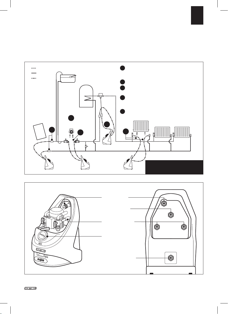
The connection point for the flushing
pump may vary depending on the
system to be cleaned, and the
availability of suitable connection
points.
However the optimum location is via
the central heating circulation pump,
using the special hoses supplied to
connect across the pump unions.
Generally the unit should be located
in a room with a suitable drain point,
and near to a convenient mains
water supply, such as a bathroom or
kitchen. The cold water supply for
a washing machine or dish-washing
machine is a convenient source
when a mixer tap makes connection
of a hose difficult. The normal
precautions during work on any
heating system should be taken, and
it is prudent to place the pump on a
waterproof groundsheet or drip tray.
1. Hose connections to the
flushing pump
1a. Ensure that both valves are in
the closed position (i.e. the valve
handles are horizontal).
1b. The pump has two 5 metre flow
and return hoses, fitted with ¾"
female brass hose connectors on
either end of each hose.
One end of both flow and return
hoses should be screwed onto
the corresponding ¾" brass
nipples on rear of the hose
support plate. The other ends of
these hoses will be connected
into the heating system.
1c. Connect the overflow hose
connector to the ¾" BSP male
overflow fitting on the rear of the
pump tank, and lead to a suitable
drain point.
1d. Connect the 8meter dump hose
to the brass nipple on the reverse
of the hose support plate, and
lead the hose to a toilet pan or
Jetflush Rapid Guidelines (19-02-15).indd 10 19/02/2015 12:13

EN
11Jetflush Rapid V1-02-15
Section B – Using the Jetflush Rapid pump for power flushing
drain pipe gully leading to a foul
sewer.
1e. Connect mains water supply
hose ¾" BSP female hose
connector to the ¾" brass nipple
on the rear of the hose support
plate. Fill the tank with water to
10cm above the minimum liquid
level, and then close the water
inlet valve.
1f. Plug in the pump to a suitable 13
amp electricity supply fitted with
an RCD adapter.
2. Hose connection to the system
Connect the flow and return hoses
of the pump to the system at the
selected point. This may be either:
2a. Across the 1½" BSP unions left
once the circulating pump has
been removed. The circulating
pump isolating valves should
be closed to isolate the flushing
pump from the system until
power flushing is commenced.
When used these are screwed
directly onto the ¾" female brass
hose adaptors of the flow and
return hoses.
2b. Across the “tails” of a
radiator (having drained and
disconnected the radiator)
using appropriate ½"or ¾"
BSP adaptors to connect to
the valves. The radiator valves
should be closed to isolate
the flushing pump from the
Jetflush Rapid Guidelines (19-02-15).indd 11 19/02/2015 12:13

EN
12 Jetflush Rapid V1-02-1 5
Section B – Using the Jetflush Rapid pump for power flushing
system until power flushing is
commenced. This is likely to be
the least effective method due to
the restrictive effect that valves
(particularly thermostatic) may
have on the flow rate.
The above method is generally
used on a combination boiler
system.
2c. Across the flow and return
connections at the boiler,
isolating the boiler itself. This
is the preferred method when
flushing a heating system prior
to installing a new boiler, as
corrosion debris may be purged
from the heating system before
the new boiler is attached. This
is important with all modern
boilers, particularly so if the new
boiler incorporates a plate type
heat exchanger with complex and
narrow water passages.
INITIAL FLUSHING PROCEDURE
(WATER ONLY STAGE, BEFORE
ADDITION OF CHEMICALS)
NOTE: In the following procedure,
the pump is first used to loosen and
mobilise loose silt and debris, before
forcibly expelling it together with
the existing heavily contaminated
system water. This rids the system
of as much debris and sludge at
an early stage, before establishing
full, chemically treated circulation
through the flushing pump.
By removing loose corrosion
products from the system before
addition of any chemical, the full
effect of the chemical is available to
disturb, loosen, and dissolve more
stubborn accumulations of debris.
Valve handle
positions
Dump
Closed
Recirculate
Flow reverser
Labels on the
handles indicate
either Dump or
Recircualte
Indicates direction
of flow
Jetflush Rapid Guidelines (19-02-15).indd 12 19/02/2015 12:13

EN
13Jetflush Rapid V1-02-15
Section B – Using the Jetflush Rapid pump for power flushing
1. Leave the pump tank cap loose,
or on by no more than one turn if
water splashes whilst flushing/
descaling (to allow gas to escape).
2. Until ready to commence
powerflushing ensure that both
valves are closed. When ready to
commence, open both valves and
open the isolating valves between
flushing pump and heating
system and switch on pump
immediately. Ensure that liquid
level in tank remains at least 10cm
above the minimum mark, adding
more water if necessary.
3. Allow the flushing pump to run for
ten minutes, reversing the direction
of flow regularly. If there is sludge
and debris in the system, the water
returning into the tank will be
heavily discoloured as the high flow
rate picks up looser debris.
4. Check all hoses and connections
for leaks.
5. The pump has the ability to dump
dirty water when the flow is in
either direction.
Change the pump into dumping
mode as follows, remembering
that the flow reverser is
constructed so that the direction
in which the lever points also
indicates the direction of flow.
5a. Operate the flow reverser lever so
that the water is flowing through
the heating system in the same
direction as it is during normal
heating operation.
5b. Rotate the valve on the return
side through 180° so that the
dump label is clearly visible.
By doing this, system water is
diverted to waste down the dump
hose, instead of returning back
into the tank. The liquid level in the
tank will immediately begin to fall.
5c. The mains water inlet supply
(orange tap) should now be
turned on and adjusted so that
the volume of incoming water
compensates for that being
forced out of the system to waste.
Continue dumping until the waste
water runs relatively clear. Ensure
that the water level in the tank
remains at least 10cm above the
minimum mark at all times.
Jetflush Rapid Guidelines (19-02-15).indd 13 19/02/2015 12:13

EN
14 Jetflush Rapid V1-02-1 5
NOTE: If the mains water cannot
keep up with the dump speed (i.e.
the unit begins to empty) simply
stop dumping until the tank fills up.
6. Once the water remains
reasonably clear, restore
circulation by rotating the valve
back through 180° into re-
circulation mode.
7. Check that the liquid level in the
tank remains 10cm (4") above the
minimum mark. Add more water
if necessary. Vent all radiators to
ensure that there are no air pockets.
Use a cloth to absorb any liquid
expelled, as the system water may
be discoloured and likely to stain.
8. The flushing chemical may now
be added.
Leave the pump tank cap loose, or
on by no more than one turn, whilst
flushing/descaling.
Section B – Using the Jetflush Rapid pump for power flushing
Position of the JetFlush
Rapid valves during normal
CIRCULATION through
the heating system
Position of the JetFlush
Rapid valves during normal
DUMPING dirty water
to waste
When flow reverser is in direction A,
waste water will be expelled through
valve A, with valve A in dump, and
valve B in recirculation
AA
B
Jetflush Rapid Guidelines (19-02-15).indd 14 19/02/2015 12:13

15Jetflush Rapid V 1-02-15
EN
Section B – Using the Jetflush Rapid pump for power flushing
CHEMICAL FLUSHING
PROCEDURE USING SENTINEL
X800 FAST ACTING CLEANER
1. Switch on the JetFlush pump.
2. Whilst re-circulating water
through the pump and the
heating system, slowly add 1 litre
of Sentinel X800 Fast Acting
Cleaner to the JetFlush Rapid
tank, sufficient for 8 – 10 radiator
(count double radiators as 2)
system, (unless it was added on a
prior visit), and ensure thorough
distribution around the system.
3. Switch on the boiler, if fitted, and
in safe working order. Allow the
system water to reach 50°C, and
then switch boiler off.
NOTE: Even boiler thermostat
setting no.1 could exceed 50°C.
4. Circulate throughout the
complete system for half to one
hour, reversing the flow direction
regularly, and monitoring the
system for leaks.
5. Close off all radiators (one valve
only), and allow the full flow to go
through the coil in the cylinder (if
present in the system).
6. Reverse the flow regularly.
7. Divert the full flow to the radiator
circuit, in preparation to putting
the full flow of the pump through
each radiator in turn.
8. Fully open both valves of the
nearest radiator, on the ground
floor, to the flushing pump.
9. Flush this radiator, reversing
the flow regularly, until all cold
spots have disappeared, and the
temperature across the radiator
is consistent. Close the radiator
valves.
NOTE: If your initial system
check identified cold or partially
blocked radiators, commence
the individual radiator flushing
procedure with the worst
radiator first, progressing to
less problematic radiators.
This ensures that the strongest
concentration of chemical is
directed at the worst areas of the
system.
10. Open the valves on the next
radiator, and repeat the procedure.
Jetflush Rapid Guidelines (19-02-15).indd 15 19/02/2015 12:13

16 Jetflush Rapid V1- 02-15
EN
Section B – Using the Jetflush Rapid pump for power flushing
11. Work through the rest of the
radiators in turn, so that you have
flushed every radiator individually,
including upstairs radiators.
12.When you have flushed the
last radiator, and it has an even
temperature across the surface,
switch the pump into dumping
mode, as previously.
13. With only this radiator open, and
the pump set to dump, run until
the water leaving the dump hose
is completely clear. Now operate
the flow reverser and change the
valves to dump in the opposite
direction until clear. When dump
water is clear, close radiator valve.
14. Go back to the previous radiator
that you had flushed, ensure both
valves are open, and repeat the
dumping procedure on this one
radiator, alternating the direction
of flow in each direction as you
dump. Close radiator valve.
15. Work your way back around the
house in the opposite direction to
previously, until you have carried
out the dumping process on every
radiator individually.
16. Now with the pump still set to dump
direct the flow through the cylinder
coil until it runs clear. Dump in the
other direction until clear.
17. If you have a TDS meter (Total
Dissolved Solids) it is useful to
test the water at this stage.
18.The reading should be compared
with a mains water sample
reading, and the dumping process
continued until both readings are
within 5–10% of each other.
19. Return the flushing pump into
normal re-circulation mode, re-open
all radiator valves, and the cylinder
coil, and move to page 20.
NOTE: When using Sentinel X800
Fast Acting Cleaner, there is no
requirement to neutralise after
the flushing process.
Jetflush Rapid Guidelines (19-02-15).indd 16 19/02/2015 12:13

17Jetflush Rapid V1- 02-15
EN
Section B – Using the Jetflush Rapid pump for power flushing
INHIBITION AND CORROSION
PROTECTION
IMPORTANT
1. The system is now full of fresh,
clean water, and in line with
Building Regulations Part L
Compliance Guide, a good quality
corrosion inhibitor, such as Sentinel
X100 Inhibitor, must be added to
the system water to prevent further
corrosion and scaling.
To comply with Benchmark
documentation, inhibitors must
have passed the Buildcert CIAS
Scheme product performance
standard and can be identified by
this logo on the pack.
UPON COMPLETION
1. Restore system to normal,
restoring radiator balance valves
to original settings, removing any
temporary isolating valves or caps
on the expansion and cold feed
pipes, and restoring non return
valves to normal operation if
necessary.
2. Before re-connecting the feed
& expansion tank, it should be
thoroughly cleaned, removing all
traces of dirty water and sludge,
and disinfected if necessary.
The inhibitor may be added to
the system by using the JetFlush
pump as follows:
3. Briefly open a dump valve to lower
the water level in the tank to just
above the minimum level, close
the dump valve. Add the Sentinel
X100 Inhibitor into the tank. Allow
circulation through the system for
ten minutes, isolate the flushing
pump from the heating system,
and switch off.
4. If the system is vented, the
residual water in the JetFlush
tank, which will contain a small
quantity of inhibitor, may be
poured into a bucket and added to
the F&E tank after this has been
cleaned.
NOTE: In a pressurised system
the inhibitor may be injected into
the system using an injector,
which will avoid wasting any
inhibitor left in the tank.
Jetflush Rapid Guidelines (19-02-15).indd 17 19/02/2015 12:13

18 Jetflush Rapid V1- 02-15
EN
Section B – Using the Jetflush Rapid pump for power flushing
QUICK GUIDE TO POWER FLUSHING WITH A JETFLUSH RAPID PUMP
1 If system is vented, cap off the cold feed and
expansion pipe.
2 Couple JetFlush Rapid pump into system.
Connect dump, water inlet, and overflow hoses to
JetFlush Rapid pump.
3 Open all radiator and lock-shield valves, and set
zone valves to manual position, for full flow
throughout system.
4 Switch on JetFlush Rapid pump, and circulate for
10 minutes, reversing flow regularly.
5 Start dumping. Adjust inlet water to ensure tank
water level remains constant. Allow to run until
dump water is clear.
6 Set JetFlush Rapid into circulation mode, with
full flow through whole system (all radiator
valves open).
7 Pour Sentinel X800 Fast Acting Cleaner flushing
chemical into JetFlush Rapid tank.
8 If possible, switch on boiler to heat water to 50°C.
Don’t leave boiler firing continuously.
9 Continue circulation through wide open system
for 15 minutes, reversing flow regularly.
10 Shut off all radiator valves except for one radiator.
Allow full flow through this one radiator for 5
minutes, reversing flow regularly.
11 Shut off first radiator, and move to second. Work
around system, putting full flow through each
radiator in turn.
12 After circulating through last radiator, switch to
dumping on that one radiator, until water runs
clear.
13 Operate flow reverser and appropriate valves to
dump with water flow in opposite direction, until
water runs clear.
14 Open up previous radiator, and dump on that until
water runs clear. Work around system in reverse,
dumping through each individual radiator in turn.
15 Restore circulation through JetFlush Rapid
pump and complete heating system (all radiator
valves open).
16 Commence final dump procedure, with all
radiators wide open. Allow to run until dump
water is clear.
17 Test that dump water is neutral, with pH paper,
and add Sentinel X100 Inhibitor to JetFlush
Rapid tank.
18 Circulate for 10 minutes before disconnecting
JetFlush Rapid, restoring system to normal
operation, and bleeding radiators.
Jetflush Rapid Guidelines (19-02-15).indd 18 19/02/2015 12:13

19Jetflush Rapid V1-02-15
EN
Section B – Using the Jetflush Rapid pump for power flushing
RADIATOR VALVE SETTINGS
Use a photo-copy of this chart to note the radiator valve settings before
commencing to power flush the system, so that the heating system can easily
be re-instated afterwards, avoiding the need to rebalance the system.
Number of turns of valve to fully closed position
Room Radiator valve Balance/lockshield valve
Hall
Cloakroom
Kitchen
Living room
Dining room
Downstairs hall
Upstairs hall
Bathroom
Bedroom 1
Bedroom 2
Bedroom 3
Bedroom 4
Bathroom 2
Other
Other
Jetflush Rapid Guidelines (19-02-15).indd 19 19/02/2015 12:13

20 Jetflush Rapid V1- 02-15
EN
Section B – Using the Jetflush Rapid pump for power flushing
POWER FLUSHING SURVEY AND CHECK LIST
Date:
Address:
Name of householder/property owner:
Tel:
Why does system need flushing?
Recommendation by
other company
Previous survey New boiler installation
British Gas/other?
Type of system:
Vented Sealed Fully pumped Gravity hot
water
Thermal
store
(Need to
cap off cold
feed and
expansion
pipes)
(Is there a
non return
valve on
return side
of radiator
circuit?) Can
gravity circuit
be closed off?
Need valve to
be fitted?
(Need to
drain down
and loop
out cylinder,
and flush
radiator and
boiler circuits
separately)
Age of system:
Boiler Radiators Pipework
Jetflush Rapid Guidelines (19-02-15).indd 20 19/02/2015 12:13
Table of contents
Languages:
Other Sentinel Water Filtration System manuals
Popular Water Filtration System manuals by other brands

Glacier bay
Glacier bay HDGDUS4 Use and care guide

Grohe
Grohe 40 438 manual

Keating Of Chicago
Keating Of Chicago Safe and Easy Filter owner's guide

Rain Bird
Rain Bird XCZ-LF-100-PRF Installation and operation

Good
Good PT4000T36-GOLD Installation & service guide

Bestway
Bestway Flowclear 58486 owner's manual