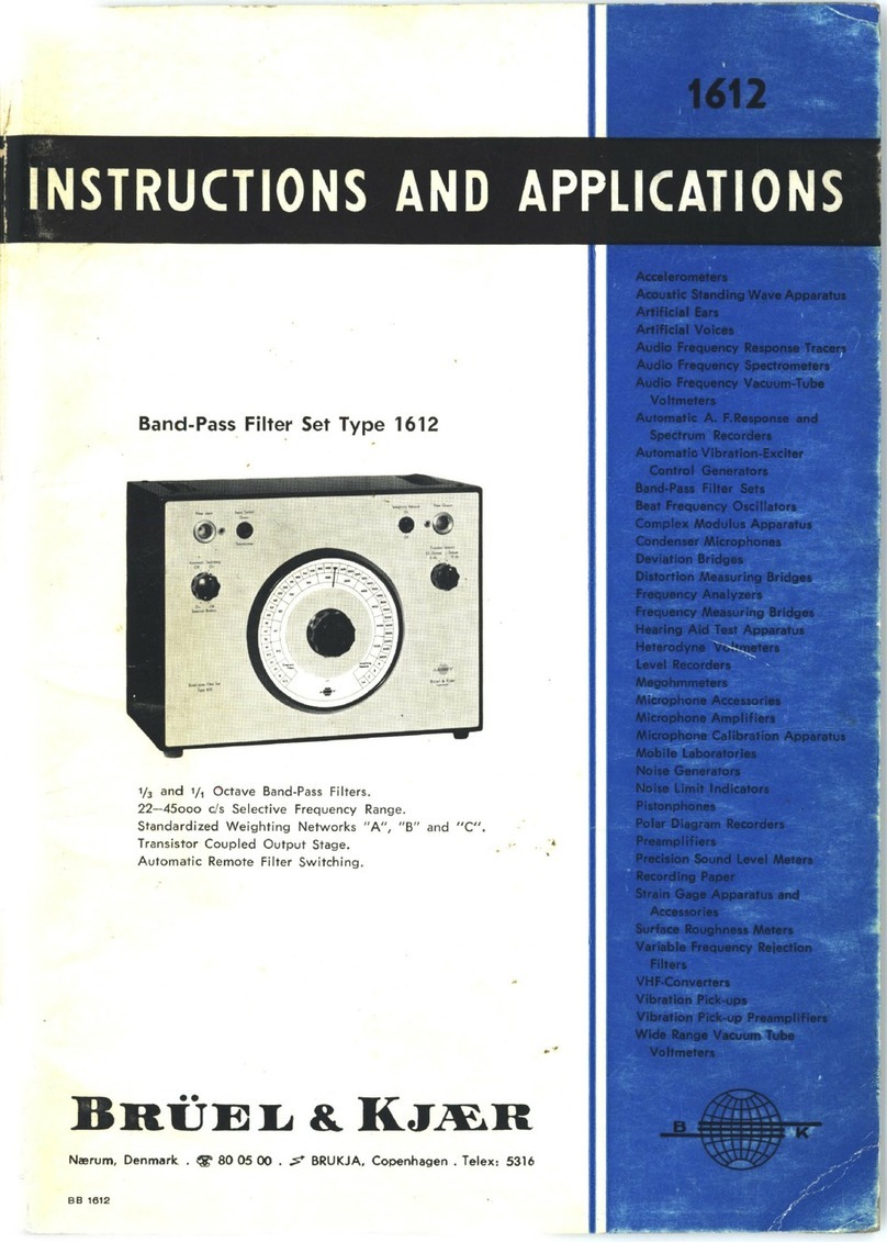
BRUEL & KJAER 1623 User manual

Instruction
Manual
Tracking Filter Type
1623
Filter
Center
Frequency
BrOel&
Kjaer
Tracking
Filter
Type
1623
Tachometer
Input
r
<;)
20mV
- 1
20V
033-0280
Trigger
level
Battery
'
Record
er
Sync
.
• • a • •
. .
.
On~
.
-
1V
+IV
r-
Manual
Tuning
/Preaet
•--,
200Hz
·I
20kHz
2Hz
1
200Hz
,----
Tracking
Mode
-._,
Tachm
. Filter Noise
In
put Input Manual Fiher
-r-1-r---
-.ndwtdth
6%
. 1
2%
23%
I
A small battery operated tracking
filter
which
can be synchronised
with
the funda-
mental frequency
or
any harmonic between
1
/99
and
99/1
of a periodic
tuning
signal.
Combined
with
a vibration meter. sound le-
vel meter,
or
measuring amplifier, the
1
623
allows
signal analysis
with
respect
to
a variable frequency reference signal, for ex-
ample vibration level
as
a function of shaft
speed. Frequency range covered is
2Hz
to
20kHz
with
filter
bandwidths
of
6%, 12%.
and 23%. Tuned frequency synchronisation
signals provided
for
the
Portable Level
Re-
corder Type
2306
and for X-V recorders.
Manual
tuning
of
the
filter
by means
of
a
front
panel
tuning
knob coupled to a
built-in
oscillator.
+ Bri.iel & Kjcer


TRACKING
FILTER
TYPE
1623
Revision
March
1
980


CONTENTS
1.
INTRODUCTION
AND
SPECIFICATIONS
(PRODUCT
DATA)
.................................................
1
2.
CONTROLS
....
........
..
.. .... ........
......
..
..
......
.
..
.....
..
....
........
..
........
.. ..
.. .... ....
....
....
........
..
..
..
..
........ 7
2.1.
FRONT PANEL
.......
.......
..
..
..
....
........
....................................
......
..............
7
2.2
. REAR PANEL
..
..............
..
..
.........
.
..
..........
........
......
............
....
..
........
..
......
10
3.
PRELIMINARY
....................................................................................................................
;
12
3.1. MOUNTING
......................
.
........
.
.............................................................
12
3.2
. POWER SUPPLY
......
....
............................................................................
13
Rechargeable Cells
(8
& K no. QB
0008)
..
.
..
........
..
................
.. ..
......
..
....
..
.
..
. 13
Dry
Cells
1,5
V
.......
.
......................................
.......
......
..................
.
..........
14
External
DC
Supply
6
to
15 V ......
..
....
..
.
..
.
.. .. ..
....
..
..
..
.
.. .. .. ..
.........
..
.
..
...
..
...... 14
Power
Supply
Type
2808
..................
..
...
..
.
.. .. .. .. ..
.....
..
........... .. .... ............. 15
3.3.
CHARGING THE INTERNAL BATIERY FROM
THE
AC
MAINS
........................
15
3.4.
FUSE REPLACEMENT
..............................................................................
16
4.
OPERATION
....................................................................
.
...................................................
17
4.1. USING THE
1623
FILTER
...............................................................
.
.........
17
4.2.
SUITABLE TUNING SIGNALS
....................................................................
17
Photoelectric
Probe MM 001-2 ..............
..
.. .......
..
... .
..
.
..
.......
..
.
..
..... ...
.. .. ..
.... 18
Magnetic
Pickup
MM
0002
..
..
............... .
.. .. ..
....
..
... ...
..
.............
..
...............
18
4.3. SETIING THE TRIGGER LEVEL
.........
..
...............................................
.
..
.....
19
4.4.
MANUALLY
TUNING
THE
FILTER ....
.. ..
.......
.. .. .. .. ..
...
..
... .... .... ......... ..
..
.....
..
.
19
4.5.
SYNCHRONISATION WITH RECORDERS
....................................................
20
Synchronisation
with
the
'Portable Level Recorders Types
2306
and
2309
....
20
Synchronisation
with
an X-Y Recorder
......
..
................................
.....
..
........
22
4.6
. USING
THE
TRACKING FREQUENCY MULTIPLIER
....................................
.
..
23
4.7. USING THE SPECIAL NOISE FILTER ....
......................................................
23
4.8.
FILTER SWEEP RATE LIMITATIONS
...........................................................
24
4.9
. TUNING FROM THE FILTERED OUTPUT SIGNAL
.........................................
25


FEATURES:
•
Battery
operated
• Frequency range 2
Hz
to
20kHz
• Three selectable
filter
bandwidths
6%, 12%,
23%
(1
/3
Octave)
•
Tunable
from
practically
any
periodic
signal
•
Manual
tuning
facility
•
Filter
frequency/tuning
signal
frequency
ratio
adjustable
between
99/1
and
1/99
•
Synchronization
signals
for
level
and
X-Y recorders
•
Wide
dynamic
range,
>60
dB,
with
crest
factor
capability
4
• Large
digital
display
of
filter
centre
frequency
•
Low-pass
noise
filter
for
tuning
signal
USES:
•
Synchronous
vibration
analysis
of
rotating
machinery
•
Harmonic
analysis
of
vibration
and
electroacoustic
signals
•
Filtering
of
response
signals
in
vibration
testing
set-ups
•
Harmonic
distortion
measurements
on
gramophone
pick-ups
19-300
type 1
623
Tracking Filter
Filter Center Frequency Trigger
level
Betterv
- -
~
--
~------~
------
Recorder
Sync.
~
11',:,//
~
L
___
- -
---------
On
Tracking
Filter
Type
1623
Introduction
The
fully
portable,
battery
oper-
ated, Tracking Filter Type 1
623
is a
narrow
bandwidth
filter
whose
cen-
tre
frequency
automatically
locks
onto
and
follows
the
fundamental
frequency,
or a
harmonic,
of
a peri-
odic
tuning
signal
originating
from,
for
example, a
tachometer
or
vibra-
tion
transducer
. Its
small
size and
built-in
battery
power
supply make
it ideal
for
field
operation
with
the
general purpose
Vibration
Meter
Type
2511.
When
combined
with
a sound lev-
el
meter,
vibration
meter,
or mea-
suring
amplifier,
sound,
vibration,
and
other
signals
which
can be con-
verted to electrical
waveforms,
can
be analyzed
as
a
function
of
a vari-
able
frequency
reference signal.
As
a typical example, can be quoted
the
synchronous
vibration
analysis
of
an
engine
being
run
up in speed;
the
vibration
level measured can be
plotted as a
function
of engine
speed, and
the
development
of re-
r Menual Tuning/Preaet '
e
2
00
Hz
20kH
z
2H
z
200H
z
,----
Tracking
Mode
~
Tachm. Filter Nol18
Input Input Manual Filter
sonances excited by
the
fundamen-
tal rotation
frequency
and its var-
ious
harmonics
can
then
be
stud-
ied.
Filters
Both
the
tuning
signal frequency
and
the
filter
frequency
ranges
cover
2Hz
to
20kHz
in one range
with
automatic
tuning.
Three con-
stant
percentage
bandwidth
filters
are provided
with
"white
noise"
bandwidths
of
6%, 12% and
23%
(
1/3
Octave)
of
the
tuned fre-
quency.
Constant
percentage band-
width
filters
give a
constant
resolu-
tion
on a
logarithmic
frequency
scale and are
therefore
able to give
a
relatively
quick
analysis over a
wide
frequency
range.
The
filter,
which
has a dynamic
range
of
about
70
dB, consists of a
digitally
tuned
pair
of two-pole
But-
terworth
filters
that
give good selec-
tivity
with
an
attenuation
of
12
dB/octave.
Characteristic curves
for
the
filters
are
shown
in Fig .1.

Mea
s
uring
Object
:
__
_
DDDDDD
DO
DDDO
D O O
OODOOOOOO
0
dB
Dat
e:
10
dB
20 dB
30dB
40dB
50 dB
100
200
Lower
Lim
. Freq
.:
Potentiomet
er: Zero Lev
% Bandwidth =
12%
Bandwidth =
3%
Bandwidth =
500
1
000
2000
5000
10000
Hz
Writ
ing
Sp
eed:
mm
l s
760855
Fig.1.
Typical
filter
characteristics
of
Track
-
ing
Filter
Type
1623
The
large
digital
display
on
the
front
panel,
showing
the
frequency
to
which
the
filter
is
tuned
, is
easily
readable in
daylight
conditions
.
Filter
Tuning
Practically
any
well
defined
peri-
odic
signal
with
a level
between
20
mV
(noise
free)
and 1
20
V peak-
to-peak
and
a
noise
level less
than
20
mV
peak-to-peak,
is
suitable
for
tuning
the
filter.
The
signal
can,
for
example,
be
obtained
from
a ta-
chometer,
photo-electric
transdu-
cer, eddy
current
probe,
accelerome-
ter,
microphone,
force
transducer,
magnetic
transducer,
capac1t1ve
transducer
etc
.
(with
suitable
pream-
plifier
where
necessary)
which
will
give a
signal
in
synchronization
with
some
periodic
motion
of
the
measuring
object.
A
manually
set
trigger
level en-
ables
the
periodicity
of
the
tuning
signal
to
be
detected
in
the
most
su-
itable
portion
of
the
waveform
;
this
adjustment
together
with
the
hyster
-
esis
effect
exhibited
by
the
trigger,
makes
it
possible
for
a
reliable
con-
trol
pulse
to
be
obtained
from
al-
most
any
periodic
waveform
.
In
addition
to
the
"tachometer"
in-
put
,
two
other
possibilities
exist
for
automatically
tuning
the
filter:
(1)
Where
the
signal
to
be
filtered
has
a
well
defined
periodic
content
it-
self,
this
can
also
provide
the tun
-
ing
signal.
(2) In cases
where
a peri-
odic
component
of
the
signal
to
be
filtered
is
not
clearly
defined,
the
fil-
ter
can be
tuned
through
any
single
decade
using
the
filter
's
own
output
as a
tuning
source.
In
this
case,
the
tracking
frequency
multiplier
facil-
ity,
of
course,
cannot
be used.
One
2
would
normally
expect
this
closed
loop
control
system
to
be
unstable,
but
with
the
un
i
que
digitally
tuned
filter
used in
the
1623,
this
is
not
the
case.
Note
that
for
ordinary
frequency
analysis
work
the
1
623
can be
auto-
matically
tuned
by
the
Sweep
Unit
Type
5555.
Photo-Electric
Transducers
for
"Tachometer
Tracking"
For analyses on
rotating
machin
-
ery, a reliable
method
of
tuning
the
filter
is by
means
of
a
photoelectric
transducer
which
gives a
well
de-
fined
pulse
each
time
a
photo-diode
or
transistor
is
triggered
by an
inter-
rupted
light
source
.
The
B &K
Photoelectric
Tachome-
ter
Probe
MM
0012
is a
combined
infra-red
light
source
and
pickup
de-
vice
built
into
a
common
housing
,
which
is ideal
for
triggering
the
1
623.
It is
positioned
up
to
15
mm
from
a
convenient
rotating
machine
part
so
that
the
light
beam
is
ref-
lected
back
from
a
contrasting
band
attached
to
the
part
. A
white
paper,
or
aluminium
foil
strip
glued
onto
a
black
background
is ideal. The de-
vice is
fitted
with
a red
filter
to
re-
duce
interference
from
mains-oper-
ated
lights.
Power
for
the
MM
001
2 is
derived
directly
from
an
extra
shield
in
the
tachometer
input
socket
(BNC)
of
the
1
623.
Fig.2.
Photoelectric
Tachometer
Probe
MM
0012,
available
as an
accessory
for
the
Tracking
Filter
Type
1623
Manual
Tuning
By
means
of
a
tuning
knob
on
the
front
panel,
the
1
623
can be
manu
-
ally
tuned
and
used as an
ordinary
tunable
bandpass
filter
for
fre
-
quency
analysis
work
in
the
field
.
The
tunable
range
from
2Hz
to
20kHz
is covered
in
this
mode
in
two
ranges
(2Hz
to
200Hz
and
200Hz
to
20kHz)
. The
frequency
tuning
knob
is also used
to
preset
the
filter
centre
frequency
to
the
ap-
proximate
starting
frequency
of
the
tuning
signal.
This
significantly
re-
duces
the
time
taken
for
the
filter
to
automatically
lock
onto
the
tuning
signal
,
especially
at
lower
frequen
-
cies.
Auxiliary
Sweep
Unit
An
alterna-
tive
to
manual
tuning
of
the
1
623
for
ordinary
frequency
analysis
work
is
the
Frequency
Sweep
Unit
Type
5555
available
on
special
order
from
the
B & K
Systems
Engineer-
ing
Group
.
The
5555
connects
to
the
tachometer
input
of
the
1
623
and
facilitates
automatic
frequency
sweep
between
two
preset
frequen-
cies selected on
the
front
panel
of
the
5555.
Start
frequencies
of
2,
20,
200,
and
2000Hz
may
be
chosen
while
the
upper
frequency
may
be set
to
20
,
200
, 2 K, and
10kHz
. Coverage
up
to
20kHz
is
possible
by
using
the
frequency
mul-
tiplier
facility
in
the
1
623
.
It
may
be seen
from
Fig.5
that
for
a
given
filtered
signal
accuracy
the
sweep
speed is
limited
at
high
fre
-
quencies
by
the
writing
speed
of
the
recorders, Types
2306
and
2309
.
At
low
frequencies
the
limit
-
ing
factor
is
the
1
623
filter
settling
time
which
in
turn
depends
on
the
filter
bandwidth
chosen
. These val-
ues are set on
the
front
panel
of
the
5555
so
that
changeover
from
one
limiting
parameter
to
the
other
is au-
tomatic
during
sweep
thus
ensuring
the
shortest
possible
analysis
time
.
The
5555
is
equipped
with
a
built-
in NiCd
battery
which
may
be re-
charged
in-situ
by
battery
charger
ZG
0113
which
is
supplied
as an
accessory
to
the
1623
.
Battery
con-
dition
is
indicated
on a
meter
.
Tracking
Frequency
Multiplier
This
facility
enables
the
filter
to
be
tuned
to
any
ratio
combination
between
1/
99
and
99
/ 1
times
the
tuning
signal
frequency,
thus
allow-
ing
any
harmonic
or
sub-
harmonic
(between
these
limits
and
within
the
frequency
limits
of
the
instru-
ment)
of
the
fundamental
of
the
measured
signal
to
be
examined
.
This
feature
makes
the
vibration
an-

Filter
Bandwidth
6% 12%
23
%
(?(?
(y
G
M
Filter
Input
Amplitude
(oot~o!l'l
Overload
!-
Detector
0 Manual
D
E
Manual
Tuning/
Auto
-Cut-
r---
out
f >
200Hz
200Hz
~
LP
Noise
Fi
lter
6
{ Noise
4~
fFilter
Schmitt
Trigger
Preset/
Digitally
Tuned
Analogue
Filter
Filter
Output
J"\
~Frequency
~
(out
of
range)
Tuning
Range
.__
_________
~
Change Recorder
Logic
Control
/
Range
Changing -
r--------<--1
Synchron-
.-------+---i
isation
-----o
Pulse
a:
Log f
(for
2306)
and 2309
Memory
~-----iTFimej
.,._
_____
,Frequency
requency Display
Logic
~
Battery Charger
-
!---(included)
12 V,
-
400mA
Preset
e---------1
~Preset
Power
Track
~Track
-Supply
0
1--
External Power Supply
Logic -
T
6Vto15VDC(4W)
J
I
t Denomina Numerator
tor
1 1 2 MHz
Tuning
Oscillator 1 1
-to-
Counter 1
to
gg
Reference
1
99
Oscillator
Divider Divider
760851
Fig.3.
Simplified
block
diagram
of
Tracking
Filter
Type
1623
alysis
of
machinery
containing
gear
wheels
and
shafts
rotating
at
differ-
ent
speeds a
relatively
simple
mat-
ter.
The
multiplication
ratio
is se-
lected and
clearly
indicated
by
two
pairs
of
tens
and
units
knobs on
the
front
panel.
Noise
Filter
A special
low-pass
filter
is
built
into
the
tracking
input
circuitry
in
or-
der
to
attenuate
high
frequency
rip-
ple
which
could
cause
false
trigger-
ing
at
low
frequencies
. If
the
noise
filter
is
switched
in,
it
automatically
becomes
inoperative
for
tuning
sig-
nal
frequencies
above
200Hz
.
This
filter
is
particularly
applicable
for
fil-
tering
out
the
1 kHz
synchronization
signal
when
the
1
623
is used
in
conjunction
with
the
Frequency
Re-
sponse
Test
Unit
Type
441
6 and
the
Test
Records
OR
2009
and
OR
2010
.
Principle of Operation
Reference
is
made
to
the
simpli-
fied
block
diagram
shown
in Fig.3 .
The
tuning
signal
is
converted
by
the
Schmitt
trigger
.
into
a
uniform
pulse
form
with
a period
time
equal
to
the
period
of
the
original
input
waveform
.
This
period
time
is
mea-
sured
by
counting
the
number
of
pe-
riods
of
oscillation
of
a 2
MHz
oscil-
lator
between
each
trigger
pulse,
and
this
number
is
then
shifted
into
the
memory
. The
tracking
frequency
multiplier
function
is achieved
by
di-
viding
the
pulse
rate
and/
or
by
di-
viding
the
oscillator
rate (in
effect
multiplying
the
pulse
rate) by
the
fi-
gure
selected
on
the
denominator
and
numerator
knobs,
respectively
.
From
the
memory,
logic
circuits
digitally
control
the
tuning
of
the
main
filter
according
to
the
calcu-
lated
period
time
. The
filter
range
is
one
decade
of
frequency,
but
range
changing
is
automatic
until
the
fre-
quency
limits
are reached,
after
which
the
out-of-range
"frequency"
lamp
lights.
The
filter
is
tuned
over
each
decade
with
a
hyperbolic
sweep
consisting
of
175
discrete
steps
. The
step
width
varies be-
tween
0,8%
and
2%
of
the
tuned
frequency
as
shown
in
Fig.4.
Due
to
the
stepwise
method
of
tuning
the
filter,
the
1623
is
not
suitable
for
use
where
phase
accurate sig-
nals
are
required.
The
memory
also
controls
the
fre-
quency
display
logic
where
the
cal-
culated
period
time
is converted
to
frequency
for
the
digital
display
. So
that
the
specified
filter
gain
accu-
racy is
not
significantly
altered, it is
recommended
that
the
frequency
tuning
is
not
swept
faster
than
indi-
cated
in
Fig.5.
This
chart
is based
on
the
filter
settling
time
. The
exam-
ple
shows
a
sweep
from
10
Hz
to
50
Hz
with
the
1
2%
bandwidth
fil-
ter
which
requires
a
minimum
sweep
time
of
5
s-
1 s = 4 s.
With
a
logarithmic
sweep,
the
sweep
rate
(determined
by
the
lowest
fre-
quency,
10Hz)
will
be 5 decades
per
minute.
The
sweep
rate
could
be
progressively
increased
with
in-
creasing
frequency
to
25
decades-
/
min
at
50
Hz
.
Recorder
Synchronization
Synchronization
signals
are pro-
vided
for
controlling
one of
the
axes
of
a
recorder
in accordance
with
the
tuned
frequency,
so
that
vibration
le-
vel
versus
frequency
or
r.
p.m
. plots
can be
made
.
Two
forms
of
synchro-
nization
signal
are provided: A
pulse
2,01,------
------
-~
1,
6+------::..-------,..--
--
----.,.,c...--1
'*-
0,8
c
0
:~
c
~
Cl
/
/
/
0,2.-""-
___
_...._
___
_.__
____
-::'
2 4 8 20
l------1
decade
of
frequency
•I
760850
Fig.4.
The
filter
is
tuned
through
each de-
cade
of
frequency
in
steps.
The
step
width
and
therefore
the
filter
defini-
tion
varies
between
0,8%
and
2%
of
the
tuned
frequency
as
shown
.
The
definition
of
the
frequency
display
va-
ries
between
0,2%
and 2%, as
traced
by
the
broken
line
3

output
representing
the
tuned
fre-
quency, on a
logarithmic
scale. This
is intended
for
controlling
the
posi-
tion
of
the
recording paper on
the
portable Level Recorder Types
2306
and
2309.
A
switch
on
the
rear
panel of
the
1
623
selects
either
for-
wards and backwards paper move-
ment
or
forwards
(increasing fre-
quency) paper
movement
only
.
Unless
the
Level Recorder Type
2306
is modified
the
recording
paper can
only
be fed in
the
for
-
ward
direction
.
Where
the
tuned
fre-
quency falls, for example due to a
reduction of
machine
r.p.
m.,
the
paper feed
will
stop. The paper feed
will
commence
only
if
that
fre-
quency (or r.p.m.) is reached and ex-
ceeded again.
Modification
Kits
for
the
Level Re-
corder Type
2306
to enable
it
to
run both backwards and
forwards
are: Kit No.
WB
0250
for
2306's
with
serial
No
.
lower
than
718
058.
Kit No.
WB
0329
for
2306's
with
serial No.
718
058
and
higher.
Two-Channel Level Recorder Type
2309
may be run in both
forward
and backward directions
under
con-
trol from
the
1
623.
The second
form
of
synchroniza-
tion signal provided is a
DC
ramp
voltage
which
is
logarithmically
pro-
portional to
the
filter
tuned
fre-
quency. This operates in both direc-
tions and is intended
for
controlling
one of
the
axes of
the
X-Y Recorder
Type
2308
.
Power
Supply
The
internal
power
supply con-
sists of six, 4
Ampere
-
hour
capacity
Nickel Cadmium rechargeable cells.
Their capacity is
sufficient
to cover
a
continuous
operating
time
of 8
hours. The separate battery
charger, Type
ZG
0113,
supplied
can recharge
the
cells
from
a com-
pletely discharged condition in
about
14
hours.
Alternatively, an external
DC
power supply of + 6 V
to
+ 15 V can
be used
to
power
the
instrument.
The external
power
supply and bat-
tery charger are connected
through
a socket on
the
rear panel of
the
1623.
4
0,25
J. I I I
Note: Valid
for
denominator settings D<10
for
D>10,
multiply
Time by
-RJ
I I I
and
multiply
Sweep
Rate
by
~--1-----l
250
500
Frequency (Hz)
760863
/ 1
Fig.5.
Chart
for
determining
the
recommended
maximum
logarithmic
frequency
sweep
rate
and
the
recommended
minimum
frequency
sweep
time
for
filtered
signal
inaccuracy
<-1
dB
(additional
to
specified
filter
gain
accuracy)
:If
CA.UttON
CH
ll.ltGE VOLTAGE
MOS
T ONLY
IE
APPUED
WHEN USING
RECHAIIGEAB
LE
BATTEIIIES
Fig.&. Rear panel
view
of
Tracking
Filter
Type
1623
Photoelectric Tachometer
Probe
MM
0012
Tracking Filter
Vibration Meter
Chart
Synchronisation
----l
I
I
L
__
_,.•..:.'
,.,
..
,.
.....
Level
Recorder 2306 or 2309
or
X-Y Recorder 2308
Filtered
Signal
Fig.7. Typical
instrument
set-
up
for
synchronous
vibration
analysis
760852

Examples of Use
Vibration
Analysis
The
1
623
is a
valuable
accessory
to
the
portable
Vibration
Meter
Type
2511
.
Fig.8
shows
the
two
instru-
ments
mounted
in a
sturdy
carrying
case
to
make
up
a
versatile
vibra-
tion
analysis
system.
With
the
two
instruments
alone,
manually-swept
frequency
analyses
can be
per-
formed;
the
addition
of
a
battery
op-
erated,
portable
Level Recorder
Type
2306
or
2309
will
permit
fre-
quency
analyses
to
be recorded
on
amplitude
and
frequency
calibrated
paper.
The
addition
of
a
tracking
pick-up
will
allow
the
vibration
ana-
lysis
of
fundamental
and
harmonic
components,
as a
function
of
a
ma-
chine
's
running
speed,
to
be
per-
formed
and
recorded. These i
nstru-
ments
combinations
are
shown
in
Fig.7 .
Fig.8
.
The
Portable
Vibration
Meter
Type
2511
combined
with
the
Tracking
Tunable
Filter
Type
1623
mounted
in
a
sturdy,
hard-foam
carrying
case
KA
2000
Monitoring/Measuring
~lerometer
Vibration Exciter
4801
+ 4813
2626
Conditioning
Amplifiers
Measuring
Amplif
i
er
2610
Tracking Filter
1623
l
~
l:
:c
~
:
:l
~l
t®
;;
:
~
:
:
·.
-
·
@
;.;
....._
_____
.....
Power Amplifier
2707
~--~~--~~
Exciter Control
1047
Filter
Tuning
Si
gnal
--,
I
I
I
I
Chart I
Synchronisation I
I
t
I
I
Constant
Level
Output I
-~
Adaptor ZM 0100 I
I I
L
__
_________
_
_j
16
0989
/2
Fig.9
.
Typical
instrument
set
-
up
for
vibration
testing
where
a
Tracking
Filter
Type
1623
is
used
for
filtering
the
test
object
response
signal
Vibration
Testing
In
swept
frequency
vibration
test-
ing, a
tracking
filter
is
often
used
to
filter
the
test
object
response
sig-
nal. A typical
instrumentation
set-
up
showing
this
application
is
shown
in
Fig.9.
Used
in
the
monitoring
of
vibra-
tion
tests,
the
1
623
will
allow
the
recording
of
both
the
fundamental
and
the
harmonic
responses
of
test
objects.
Harmonic
Distortion
Measure-
ments
on
Audio
Systems
Recording
the
various
harmonic
components
produced
by
audio
rep-
roduction
systems
is
straight-for-
ward
when
using
the
Tracking
Filter
Type 1
623.
The
sweeping
fre-
quency
test
signal
from
a
sine
gen-
Pickup under Test
erator
or
test
recording
is also used
to
tune
the
tracking
filter
, and
the
required
harmonic
is selected on
the
1623
multiplier-divider
facility.
I I
t
Measuring Amplifier
2610
Chart Synchronisation 1
~-------....J
Level
Recorder
2307 Filtered
nal
Tracking Filter
1623
760853
/ 1
Fig.1
0.
Instrument
set
-
up
for
plotting
harmonic
distortion
curves
for
gramophone
pick
-
ups
5

A special
filter
·is
included
in
the
1
623
to
attenuate
the
1 kHz
syn-
chronization
signal
which
precedes
Filter
Frequency
Range:
2Hz
to
20kHz
continuously
tunable
from
tachometer
input
Manual
Tuning:
2Hz
to
200Hz
200Hz
to
20kHz
Filter
Bandwidth:
Switchable
effective
noise
bandwidths
of
6%,
12%,
and
23%
(
~
1/ 3 octave) con-
stant
percentage
bandwidth
plus
linear
position
(3
dB
bandwidths
of
5,4%
,
10,8%
and
21,7%)
Filter
Type:
Two-pole
Butterworth
band-pass
filter
Filter
flank
Slope:
12
dB/octave. (See
Fig .1.)
Octave
selectivity
(±1
dB):
6% B/ W
57,5
dB
12%
B/ W
45,5
dB
23%
B/ W
34
,1 dB
Dynamic
Range:
>
60
dB
under
1 V RMS
plus
crest factor
4
Digital
Display:
Gas display
shows
filter
centre
frequency
Overall
accuracy:
± 1.5%
Filter
Input:
BNC socket
Max.
level: 4 V peak
Input
impedance:
1
MO
Max.
DC
offset:
42
V
DC
Filter
Output:
BNC socket
Output
impedance:
< 1 0
Load
impedance:
;;.
500
0
DC
offset
at
output:
< 2
mV
Filter
Gain:
0 dB
with
following
accuracy
Bandwidth
2 Hz to
2kHz
2kHz
to
20kHz
6% ±1 dB ±
2dB
12%
±
0,5
dB ±1 dB
23%
±
0,25
dB ±0,5 dB
additionally
+ 0 dB
-1
dB
accuracy
for
fil-
ter
sweep
in
accordance
with
Fig.5
each
test
band
on
the
B & K
Stereo
Test
Records
OR
2009
and
OR
2010.
An
instrumentation
set-up
Specifications 1
623
Noise:
< 1
mV
RMS
Distortion:
<
0,1%
Tuning
Signal
("Tachometer")
Input:
BNC socket
(with
double shield)
20
mV
to
1
20
V peak-to-peak
Max.
Signal:
including
DC
offset
42
V
RMS
Maximum
noise:
20
mV
peak-to-peak
Input
impedance:
10
MO
Frequency
range: 2
Hz
to
20kHz
Power
supply
for
pickup on
inner
shield
of
socket + 7.5 V (direct
internal
connec-
tion
to battery )
Trigger
Level:
Adjustable
+ 1 V to
-1
V
Hysteresis:
20
mV
Sweep
Rate:
See Fig.5
Frequency
Multiplier:
1/
99
to
99
/ 1
of
tuning
signal
frequency
Output
of
Tuned
Frequency
for
Recorder
Synchronisation:
Rear
panel
connection
through
8-pin
DIN
socket
1. Log f
----7
pulse
for
B & K Level Recor-
der
Types
2306
and
2309
Max.
sweep
rate: 2 s/ decade
Frequency
accuracy
of
pulse
out-
put:±
2%
2. Log
f~DC
for
X-Y recorder e.g. Type
2308
Range
2Hz
to
20kHz
covers 0 to 7 V
Output
impedance:
2,2 kO
Max.
sweep
rate:
2 s/ decade
Frequency
accuracy
of
DC
output:
±2%
for
performing
harmonic
distortion
measurements
on
gramophone
pick-
ups
is
shown
in
Fig.1
0.
Environmental
Conditions:
The
instrument
performs
within
specifica-
tions
under
the
following
conditions
:
Temperature:
-1
0°C
to
+
50°C
Humidity:
0 to
95%
relative
humidity,
non
condensing
Electromagnetic:
Field
strengths
up
to
100A
/ m
Internal
Power
Supply:
6 x NiCd rechargeable cells
Operating
capacity:
8
hours
continuous
External
Power
Supply:
Rear panel
connection
through
7-pin
DIN
socket
Requires+
6 V
to+
15
V,
3,5
W
Battery
Charger:
B&KTypeZG0113
Input:
1
00
to
1
30
V AC
or
200
to
240
V
AC
Output
:
12
V
400
rnA.
Short
circuit
pro-
tected
Time
for
complete
recharge:
approx. 14
hours
Dimensions:
(excl. feed knobs etc.)
Height:
133
mm
(5,2
in)
Width
:
210
mm
(8,3
in)
Depth:
200
mm
(7,9
in)
(B
& K
module
cabinet
KK
0025
. 6/
12
of
1
9"
rack module)
Weight:
Including
batteries, 3,2
kg
(71b)
Accessories
Included:
3 BNC
plugs
JP
0035
7-pin
DIN plug
JP
0703
8-pin
DIN plug
JP
0802
6 NiCd cells QB
0008
Battery
charger
ZG
011
3
Spare fuses
VF
0032
Accessories
Available:
Photoelectric
Tachometer
Probe
MM
0012
Sweep
Unit
Type
5555

2.1.
FRONT
PANEL
Filter
Center
Frequency
Brtiel&KjSIII'
Tracking
Filter
Type
1623
Tachometer
Input
20mV
-
120V
Max.
42V
RMS
2.
CONTROLS
Trigger Level
Bettery
r-
Manual Tuning/
Preset
~
.
200Hz
120kHz
2Hz
200Hz
•
Recorder
Sync
.
~
r---
Tracking
Mode
~
Tachm
.
Filter
Noise
Input Input Ma
nual
Filter
r--
r--
r--
--
- . I
Bandwidth
6%
12% 23%
Lin
.
I
Fig.2.
1.
Front
panel
of
the
Tracking
Filter
Type
1623
FILTER CENTER FREQUENCY: A
digital
display
of
the
centre
frequency
to
which
the
filter
is tuned;
with
either
Hz
or
kHz
illuminated.
Frequency:
When
illuminated
indicates
that
the
signal
from
the
tuning
source
selected (possibly
modified
by
the
setting
of
the
TRACKING FRE-
QUENCY MULTIPLIER knobs) is
outside
the
frequency
range 2
Hz
to
20kHz.
Synchronisation
signals
to
recorders
are blocked
when
the
Fre-
quency
lamp
lights
but
synchronisation
is
not
lost.
Amplitude:
When
illuminated
indicates
that
the
filter
input
signal
level
exceeds 4 V peak.
Preset:
When
illuminated
indicates
that
the
filter
is
not
being
tuned
by
a
Tachometer
Input
signal
or
Filter
Input
signal
and
is
therefore
auto-
matically
tuned
to
the
frequency
determined
by
the
setting
of
the
MAN-
UAL
TUNING/PRESET
knob
multiplied
by
the
N/ D
ratio
set on
the
TRACKING FREQUENCY MULTIPLIER.
Track:
When
illuminated
indicates
that
the
filter
is
being
tuned
by
the
tuning
signal
selected
by
depressing
either
the
Tachometer
Input
or
Filter
Input
or
Manual
pushbuttons.
7

TACHOMETER INPUT:
TRIGGER LEVEL:
BATTERY:
TRACKING MODE:
BANDWIDTH:
MANUAL
TUNING/PRESET:
TRACKING FREQUENCY
MULTIPLIER:
RECORDER SYNCHRONISATION:
8
A BNC socket
accepting
either
single
or
double
shielded
BNC
plugs
for
a
tuning
signal
input.
The
inner
shield
is
connected
through
the
On/Off
switch
to
the
built-in
battery
supply
(+
7,5
V)
and is
intended
for
powering
a
photoelectric
pickup (e.g. B & K Type
MM
0012).
Signal
level
20
mV
(noise free)
to
1
20
V peak-to-peak.
Maximum
signal
level
including
DC
offset
42
V
RMS.
Noise
level less
than
20
mV
peak-to-
peak.
Input
impedan
'ce
10
MO.
For
positioning
a
20
mV
wide
amplitude
window,
through
which
the
tuning
signal
is
viewed,
within
the
range
± 1 V. Enables
the
periodicity
of
the
tuning
signal
to
be detected
in
the
most
suitable
portion
of
the
waveform.
Toggle
switch
which
applies
power
to
the
instrument.
The
adjacent
me-
ter
indicates
if
the
instrument
is
powered
(by
the
internal
or
an
exter-
nal
supply) and
if
the
supply
voltage is
sufficiently
high
(blue/green
area)
or
whether
the
supply
voltage is
too
low
or
the
battery
should
be
charged (red area < 6 V).
Three
pushbuttons
which
select
the
source
of
tuning
signal
for
the
fil-
ter.
Tachm.
Input:
Selects a
signal
applied
to
the
TACHOMETER INPUT
Socket.
Filter
Input:
Selects
the
signal
applied
to
the
FILTER INPUT socket
(rear panel).
Manual:
Allows
filter
tuning
by
means
of
the
MANUAL
TUNING knob.
Noise
Filter:
Connects
a special
low-pass
noise
filter
into
the
tuning
circuit
to
attenuate
high
frequency
noise
in
the
tuning
signal.
It
be-
comes
automatically
inoperative
for
tuning
signals
above
200Hz.
See
section
4.
7.
Four
pushbuttons
to
select
effective
filter
bandwidths
of
6%,
12%,
23%
("' 1
/3
Octave),
or
Linear.
In
the
linear
position
the
filter
input
is
connected
directly
to
the
output
socket.
With
the
TRACKING
MODE
-
Manual
pushbutton
depressed
the
tun-
ing knob can
manually
tune
the
filter
over
the
frequency
range
2Hz
to
20kHz
in
two
ranges,
2Hz
to
200Hz
and
200Hz
to
20kHz
as se-
lected on
the
adjacent
slide
switch.
Whenever
the
Preset
window
in
the
display
is
illuminated
the
filter
is
tuned
to
the
frequency
deter-
mined
by
the
position
of
the
MANUAL
TUNING/PRESET
knob
multi-
plied
by
the
N/D
ratio
set
on
the
TRACKING FREQUENCY MULTIPLIER.
Four
ten-position
switches
which
multiply
the
tuning
signal
fre-
quency
by
the
ratio
indicated
by
the
upper
(Numerator)
knobs and
lower
(Denominator)
knobs. The
centre
frequency
of
the
filter
is
there-
fore
tuned
to
the
tuning
signal
frequency
x
N/D.
All
ratios
between
1/99
and
99/1
are selectable.
Three
pushbuttons
which
direct
the
filter-to-recorder
synchronisation
circuitry.
These
comments
apply
to
operation
with
the
Portable Level

Recorders Types
2306
and
2309.
(Comments
in
parentheses
apply
to
operation
with
an X-Y
recorder,
eg. Type
2308)
.
Reset
Forward:
When
pressed, resets
the
pulse
counter
in
the
synchro-
nisation
system
to
0
position.
Can take up
to
10
s
to
achieve
this
condi-
tion.
With
an
already
synchronised
level (X-Y) recorder, pressing
the
Reset
Forward
button
will
move
the
paper (pen)
forward
to a
"reset
"
position
on
the
next
(same)
chart
about
4
mm
before
the
2Hz
line
when
paper QP
0120,
QP
0143
or
QP
0124
is
fitted
to
the
level recor-
der.
Reset
Reverse:
When
pressed, resets
the
pulse
counter
in
the
synchro-
nisation
system in
the
reverse
direction
to
0
position.
With
an already
synchronised
level (X-
Y)
recorder, pressing
the
Reset
Reverse
button
will
move
the
paper (pen)
backwards
to
a
position
on
the
chart
about
4
mm
before
the
2Hz
line
when
paper QP 01
20,
QP
0143
or
QP
0124
is
fitted
to
the
level
recorder.
Applies
only
for
Level Recorder
Type
2309
and
when
the
Level Recorder Type
2306
is modified
for
backwards
movement
and
when
the
RECORDER SYNC. slide
switch
is
in
the
Fwd.
& Rev.
position.
Start:
When
pressed, indexes
the
pulse
counter
in
the
synchronisation
system
forward
to
a
condition
in
agreement
with
the
frequency
indi-
cated by
the
frequency
display.
With
an
already
synchronised
level (X-
Y)
recorder, pressing
the
"Start"
button
will
move
the
paper (pen)
for-
ward
to
this
frequency.
Holding
the
Start
pushbutton
in
the
depressed
position
locks all
out-
puts
from
the
RECORDER SYNC. socket.
This
prevents
the
recorder
paper (pen)
moving
backwards
and
forwards
while,
for
example,
adjust-
ment
are
being
made
to
the
tuning
of
the
filter.
Synchronisation
with
recorders is NOT lost,
on
release
of
the
Start
button
the
recorder
paper (pen)
will
move
directly
to
the
tuned
centre
frequency.
9

2.2.
REAR
PANEL
·
f'~
·
Fwd.&
liF!
·I· Rev.
Fwd
.
"Only
E.
><t
. Power Supply Filter
Output
Made in Denmark
)f
CAUTION
CHARGE
VOLTAGE
MUST
ONLY
BE
APPliED
WHEN
USING
RECHARGEABLE BATTERIES
Fig.2.2.
Rear
panel
of
the
Tracking
Filter
Type
1623
RECORDER SYNC.:
An
8
pin
DIN socket
giving
access
to
the
various
synchronisation
sig-
nals
for
X-Y and level recorders.
10
Pin 1
carries
forward-reverse
instruction
for
Level Recorder Type
2306
and
2309.
Pin 2
signal
ground.
Pin 4
carries
pen
down
instruction
for
Level Recorder Type
2309
and
for
an
X-Y
recorder.
When
RECORDER SYNC. Reset
Fwd.
or
Reset Rev.
are
depressed
pin
4,
which
is
normally
grounded,
is
opened
to
lift
the
pen
until
the
reset
condition
is
achieved.
Pin 7
carries
a
pulse
output
for
automatic
synchronisation
of
the
re-
cording
paper on
the
Portable Level Recorders Type
2306
and
2309.
Pin
8
carries
a DC
ramp
voltage
which
is
logarithmically
proportional
to
the
filter
tuned
frequency
(2Hz
to
20kHz
covers approx. 0
to
7 V).
Intended
for
controlling
one
of
the
axes
of
an
X-Y
recorder.
DC
ramp
for
X-
Y recorder
0-7
V =2
Hz-
20kHz
Output
impedance 2,2
k.Q
Ground
Paper
synchronization
for
2306 and 2309
Pen
lift
for
2309 and
for
X-Y
recorder
(Pin 4
normally
grounded,
is
opened
while
1623
is
resetting)
110306
/ 1
Fig.2.3
.
Pin
designations
for
RECORDER SYNC.
socket
viewed
from
outside

EXTERNAL POWER SUPPLY:
The adjacent slide
switch
is set
to
Fwd.
& Rev.
(forward
& reverse)
when
the
1623
is used
with
an X-Y recorder, a Level Recorder Type
2309
or
a Level Recorder Type
2306
which
has been modified (see
p.4
for
Kit No.'s)
to
run
in
both
directions.
The
Fwd.
Only
position is
selected
when
working
with
unmodified
Type
2306
Level Recorders.
A 7 pin DIN socket
for
connection
of
an
external
supply
for
powering
the
instrument
(+ 6 V to + 15 V
DC)
and a + 12 V charging voltage
for
recharging
the
internal
batteries. See section
3.2.
Pin
designations
are
as
shown
in
Fig.2.4.
Power
consumption
is approx.
3,5
W.
The
adjacent
slide
switch
selects
either
External
Power
supply
or
Inter-
nal
Battery
for
powering
the
instrument.
+ 12 V charging
--+---
---+----+
6 V
to
+15 V
voltage
Power supply
ground
power supply
770305
Fig.2.4.
Pin
designations
for
EXT. POWER SUPPLY socket
viewed
from
outside
FILTEA INPUT: A BNC socket
for
applying
the
signal
to
be
filtered.
Nominal
input
level
1 V RMS. Crest
factor
capability
4.
Input
impedance 1
MO.
Maximum
allowable
DC
offset
42
V DC.
FIL
TEA
OUTPUT: A BNC socket
for
feeding
the
filtered
signal
out
of
the
instrument.
Out-
put
impedance < 1
0.
Required load impedance
~
500
0.
DC
offset
at
output<
2 mV.
BATIERY
COVER
R_ELEASE
Enables
the
side plate
to
be removed
for
access to
the
internal
re-
SCREW: chargeable cells.
11

3.1.
MOUNTING
12
3.
PRELIMINARY
The
1623
cabinet
is
designed
to
fit
the
B & K
modular
cassette
system.
Its
width
is
6/ 12
of
the
width
of
the
combining
frame
KK
0014
and
the
carrying
case
KA
2000
so
that
it
can be,
for
example,
combined
with
the
General
Purpose
Vibration
Meter
Type
''I
2511
(also 6/ 12
wide)
to
fill
either
of
these.
To
mount
the
1
623
into
the
combining
frame
or
the
carrying
case,
first
remove
the
base
panel
of
the
1
623
by
loosening
the
base
securing
screw
on
the
front
panel,
remove
the
rubber
feet
and
inclining
leg,
then
remount
the
base panel
into
the
base
of
the
combin-
ing
frame
or
carrying
case.
The
1
623
can
then
be
slid
into
position
and
fastened
with
the
securing
screw
on
the
front
panel.
Mounting Frame
KK
0014
r
(with
19"
rock
mo""'log
brock•")
Fig. 3.
1.
The
cassette
combining
system
770318

Fig. 3.2. The
Portable
Vibration
Meter
Type
2511
combined
with
the
Tracking
Filter
Type
1623
mounted
in
a
sturdy,
hard-
foam
carrying
case KA
2000
3.2.
POWER
SUPPLY
There
are
several
methods
of
supplying
power
to
the
1
623,
they
are
described
in
the
fol-
lowing
subsections
.
Whichever
supply
method
is used,
check
that
the
battery
condition
indicating
meter
deflects
to
the
blue/green
area,
thus
indicating
sufficient
supply
vol-
tage
.
3.2.1.
Rechargeable
Cells
(B & K
no.
QB
0008)
Six
rechargeable
nickel-cadmium
cells
are
supplied
with
the
1623.
They
are
each
rated
at
1
,2
V
with
a
capacity
of
4
Ah
and
are
specified
to
give
at
least
500
charge
cycles be-
fore
replacement
i·s
necessary.
The need
for
replacement
is
indicated
by
the
cells
failing
to
reach a
fully
charged
condition
after
being
left
on
charge
for
14
hours
or
more
(with
battery
charger
ZG
0113
supplied). A
fully
charged
battery
can
be
expected
to
give
a
con-
tinuous
operating
capacity
of
8
hours.
The
cells
are
mounted
in
the
1
623
as
follows:
1. Lay
the
instrument
on its left side panel
(viewed
from
the
front)
imd
remove
the
screw
marked
Battery
on
the
rear panel. The side
panel
can
now
be slid
out
of
the
instrument
body.
2.
Place
the
cells
in
the
compartment
with
their
polarities
as
indicated.
(See
Fig.3.3.)
WARNING:
There
is a
possibility
of
explosion
if
recharging
is
attempted
on
cells
that
have
been
fitted
with
their
poles reversed.
3.
Replace
the
side
panel
and
stand
the
instrument
on
its
feet,
or
use
the
stand
to
raise
the
front
panel
as desired.
4.
Slide
the
power
supply
switch
on
the
rear panel
to
Internal
Battery.
5.
Set
the
BATIERY
switch
to
On,
and
check
that
the
battery
condition
indicating
me-
ter
registers
in
the
blue/green
area,
indicating
that
the
battery
is in
usable
condi-
tion
.
13

Fig.
3.
3.
Location
of
the
six
cells
in
the
battery
compartment
of
the
Type
1623
6.
Switch
the
instrument
Off
to
conserve
battery
power
if
it
is
not
to
be
used
immedi-
ately.
Note
that
the
Battery
Charger
Unit
ZG
0113
has
a
current
capability
which
is
about
equal
to
the
current
consumption
of
the
1623
when
operating,
so
that
with
well-
charged
cells,
the
ZG
0113
will
act
as
an
AC
Mains
power
adaptor.
(The
power
supply
slide
switch
on
the
rear panel is
set
to
Int.
Battery.)
3.2.2.
Dry
Cells
1,5
V
Ordinary
1,5
V
dry
cells
to
IEC
R
20
(33
mm
x
60
mm
high)
can
also be used.
"Long
Life"
alkaline
cells
will
give an
operating
capacity
of
about
12
hours
continuous
opera-
tion
while
ordinary
cells
will
give
0,5
to
2
hours.
Never
attempt
to
recharge
ordinary
or
alkaline
cells
-
there
is
a
danger
of
explosion.
3.2.3.
External
DC
Supply
6
to
15
V
14
A
car
battery
or
other
DC
source
of
between
6 V
and
15 V
with
a
power
capability
of
at
least
3,5
W can be used to
power
the
1623.
The
source
is
connected
to
the
1623
via
the
rear
panel socket marked EXT. POWER SUPPLY
with
the
connections
shown
in
Fig.3.4.
+
6 V
to
15 V
;;;.
3,5 w
7
Pin
DIN
Plug
JP
0703 '
+ 6 V
to+
15 V
~--------------------~ov
770303
Fig.3.4.
Connections
for
external
power
supply.
Soldering
side
of
plug
shown
Table of contents
Other BRUEL & KJAER Water Filtration System manuals