Bruker BioSpin CryoProbe RF CRP RF UNIT User manual

Bruker BioSpin
Version
CryoProbe RF
ELECTRONICS
Technical Manual
003

The information in this manual may be altered without notice.
Bruker BioSpin accepts no responsibility for actions taken as a
result of use of this manual. Bruker BioSpin accepts no liability
for any mistakes contained in the manual, leading to coinciden-
tal damage, whether during installation or operation of the in-
strument. Unauthorised reproduction of manual contents,
without written permission from the publishers, or translation
into another language, either in full or in part, is forbidden.
This manual was written by
Pietro Lendi and Walter Roeck
© September 4, 2002: Bruker BioSpin AG
Fällanden, Switzerland
P/N: Z31474
DWG-Nr: 1177003

Technical Manual Index 003 Bruker BioSpin 3 (33)
Contents
Contents ............................................................... 3
1 General Description .............................................. 5
1.1 Introduction ......................................................................... 5
1.2 Features .............................................................................. 5
1.3 CRP RF UNIT vs HPPR CRP (HPPR/2) MODULE ............... 6
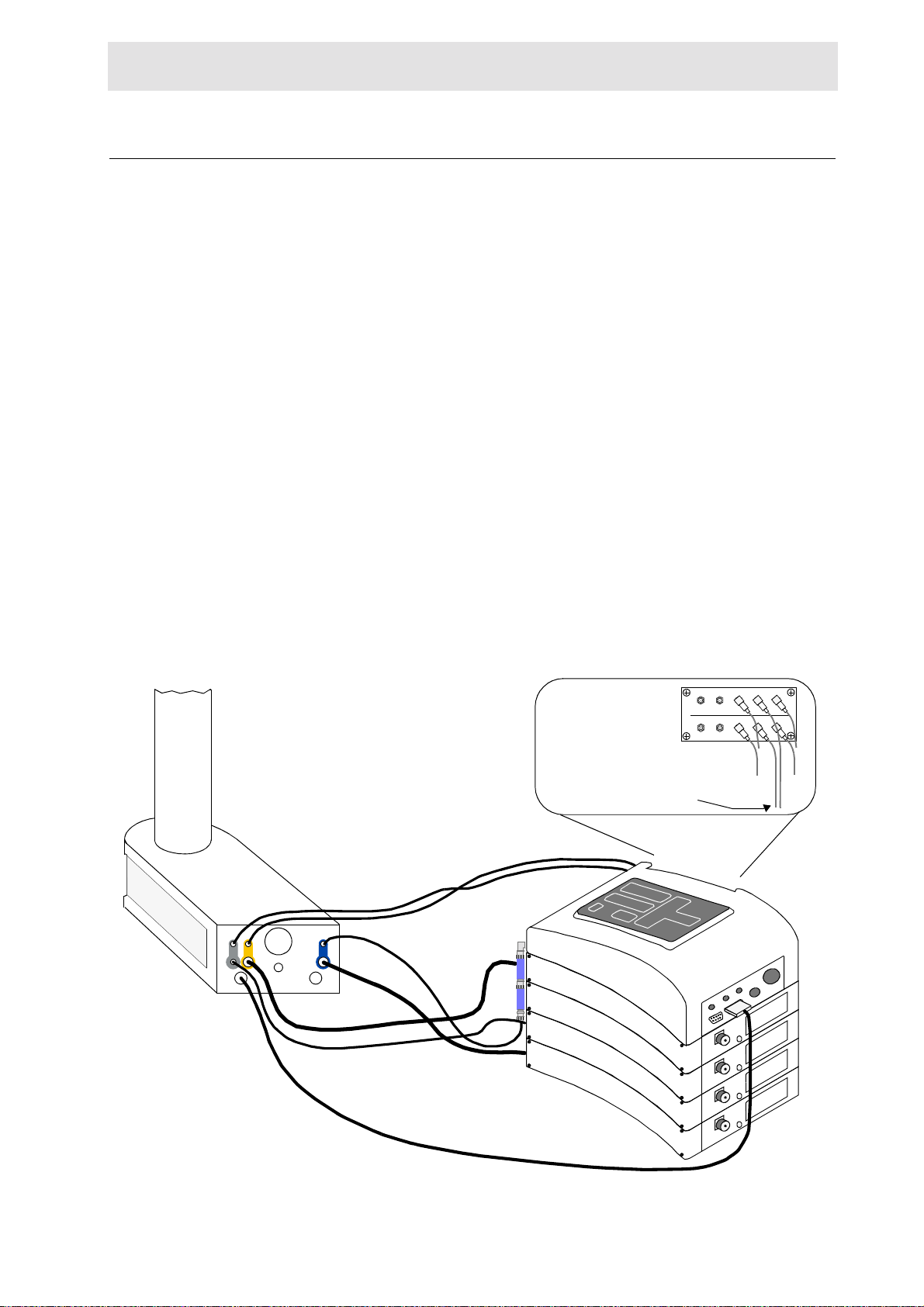
1.4 RF Wiring for a CP DUL C/H-D or CP DUI H/C-D
(HPPR CRP) ....................................................................... 7
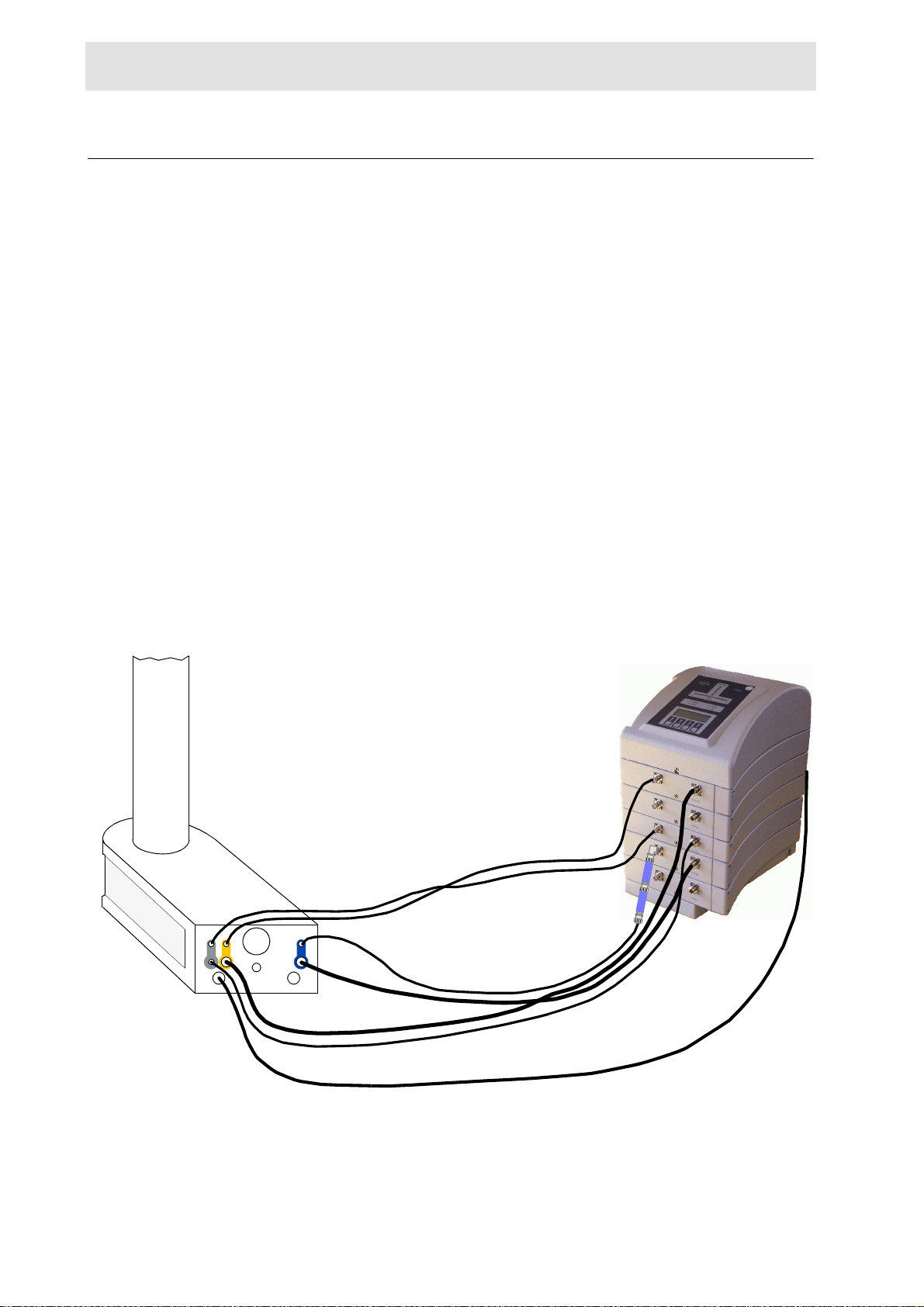
1.5 RF Wiring for a CP DUL C/H-D or CP DUI H/C-D
(HPPR/2 family) .................................................................. 8
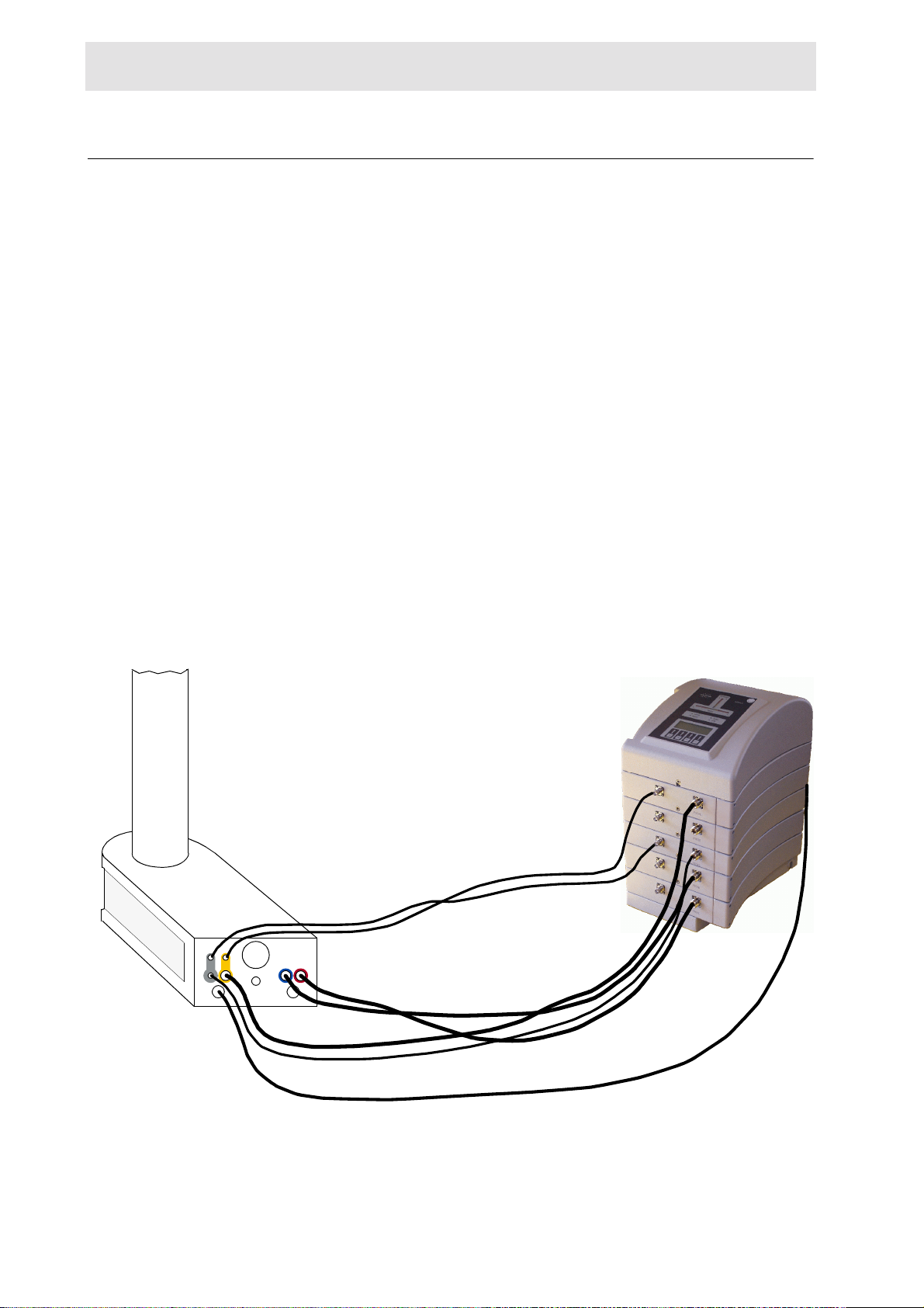
1.6 RF Wiring for a CP TXI H-C/N-D (HPPR CRP) ..................... 9
1.7 RF Wiring for a CP TXI H-C/N-D (HPPR/2 family) .............. 10
1.8 RF Wiring for a Conventional Probe (HPPR CRP) .............. 11
1.9 RF Wiring in case of existing standard HPPR MODULEs ... 12
Combination with a HPPR 19F or a 3H MODULE ...........12
Combination with a HPPR X-BB31P 2HS MODULE ........12
Combination with a HPPR X-BB19F 2HP MODULE ........12
Combination with HPHP 19F/1H/3H & X-BB MODULEs ..12
2 Operation ............................................................ 15
2.1 CryoProbe Operation with HPPR/2 ASSEMBLY ................. 15
2.2 CryoProbe Operation with HPPR CRP ASSEMBLY ............ 16
HPPR CRP Installation Software for XWIN-NMR ............16
XWIN-NMR selection of observe and decoupling nuclei
(HPPR CRP only) ..........................................................16
HPPR CRP COVER RF selection control .......................17
3 RF UNIT 1H13C2H Technical Data ...................... 19
3.1 General ..............................................................................19
3.2 Power Consumption .......................................................... 19
3.3 Transmit-/Receive Bias Currents ....................................... 20
4 RF UNIT 1H13C2H15N Technical Data ................ 21
4.1 General ..............................................................................21
4.2 Power Consumption .......................................................... 21
4.3 Transmit-/Receive Bias Currents ....................................... 22
5 Service Information ............................................ 23
5.1 General ............................................................................. 23
5.2 Basic System Checks ........................................................ 23
5.3 Block Diagrams (HPPR and HPPR/2 family) ...................... 24

Technical Manual Index 003 Bruker BioSpin 5 (33)
General Description1
1000000
Introduction 1.1
0 The introduction of a new family of high-performance cryogenic probes represents
a major step forward in NMR instrumentation.
Developed in order to cover a huge number of chemistry applications, the Cryo-
Probes offer outstanding performance with respect to signal-to-noise and mea-
surement time.
This manual covers:
•Installation of the rf wiring for different types of CryoProbes
•Software description
•Technical data
•Some service informations
Most of the information given in the ‘HPPR Technical Manual‘ (Z31075) and
‘HPPR/2 Technical Manual’ (Z31559) remains valid for the HPPR CRP MOD-
ULEs.
Features 1.2
0 •Practical and easy-to-use.
•Integrated cryocooled preamplifiers, filters and t/r-switches make maximum
use of the significant signal-to-noise improvement in a cryogenic cooled signal
detection system.
•Additional functionality is offered in conjunction with the HPPR CRP ASSEM-
BLY as for example:
- Computer controlled signal routing between the CryoProbe and the
HPPR CRP MODULEs respectively HPPR/2 MODULEs
- Improved spectral purity of the rf pulses by using the built-in filters of the
HPPR CRP MODULEs (HPPR/2 MODULEs)
- Probe tuning of all nuclei
- PICS (Probe Identification System)

6 (33) Bruker BioSpin Technical Manual Index 003
General Description
CRP RF UNIT vs HPPR CRP (HPPR/2) MODULE 1.3
0 •HPPR CRP (HPPR/2) MODULE:
- filters the transmitted signal
- is used for probe tuning and matching
- selects the received signal FT-REC
- has full functionality for conventional probes
•CRP RF UNIT:
- contains transmit/receive switches
- contains cryocooled preamplifiers
- filters received signal
- PICS
1HCRP
2HCRP
13CCRP
X-BB19F2HS
2H1H
IN
OUT
IN
OUT
J1 J2
13C
IN
OUT

RF Wiring for a CP DUL C/H-D or CP DUI H/C-D (HPPR CRP)
Technical Manual Index 003 Bruker BioSpin 7 (33)
RF Wiring for a CP DUL C/H-D or CP DUI H/C-D (HPPR CRP) 1.4
0 The standard HPPR CRP ASSEMBLY for a CP DUL C/H-D or CP DUI H/C-D
consists of the following parts:
•HPPR CRP COVER MODULE
•HPPR 1H CRP MODULE
•HPPR 2H CRP MODULE
•HPPR X-BB19F 2HS MODULE
•HPPR 13C CRP MODULE
The HPPR CRP MODULEs are almost identical to the well known HPPRs used
for a conventional probe with exception of partly different filter characteristics and
additionally included functions used for the CryoProbe. However, every HPPR
CRP MODULE may be used for either CryoProbe operation or with a convention-
al probe. For CryoProbe operation pull the ribbon cable connectors at the JUNC-
TION BOARD of the HPPR X-BB19F 2HS MODULE!
NOTES:
1. The HPPR XBB19F 2HS MODULE is used ONLY for operation with a conven-
tional probe.
2. In general, no external filters are required between the HPPR MODULEs and
the CryoProbe (exeption: connetion from CP 13C RF OUT to HPPR 13C RF IN).
Figure 1.1. RF wiring for a CP DUL C/H-D or DUI H/C-D (HPPR CRP)
1HCRP
2HCRP
13CCRP
X-BB19F2HS
HPPR CRP FILTER SET 1H13C2H
Connect the
to the ‚XBB RF-IN‘ BNC-cable jack
2H1H
IN
OUT
IN
OUT
J1 J2
13C
IN
OUT
TUNING - SPLITTER
PREAMPLIFIER - SELECTOR
19F UB 2H X-BB 1H
19F UB 2H X-BB 1H
from / to HPPR CRP
2H MODULE
from / to HPPR CRP
1H MODULE
from / to X-BB19F 2HS MODULE or
(plugged at the SELECTOR manually)
MANUAL CONNECTOR
CONFIGURATION OF
THE SELECTOR
13C CRP MODULE
CP DUL C/H-D
1H RF IN
2H RF IN

8 (33) Bruker BioSpin Technical Manual Index 003
General Description
RF Wiring for a CP DUL C/H-D or CP DUI H/C-D (HPPR/2 family) 1.5
0 The standard HPPR/2 ASSEMBLY for a CP DUL C/H-D or CP DUI H/C-D con-
sists of the following parts:
•HPPR/2 COVER MODULE
•HPPR/2 1H LNA MODULE
•HPPR/2 2H MODULE
•HPPR/2 XBB19F 2HS MODULE
•HPPR/2 13C MODULE
HPPR/2 MODULEs may be used for either CryoProbe operation or with a conven-
tional probe.
NOTES:
1. The HPPR/2 XBB19F 2HS MODULE is used ONLY for operation with a con-
ventional probe.
2. In general, no external filters are required between the HPPR/2 MODULEs
and the CryoProbe (exeption: connetion from CP 13C RF OUT to HPPR 13C
RF IN).
Figure 1.2. RF wiring for a CP DUL C/H-D or DUI H/C-D (HPPR/2 family)
2H1H
IN
OUT
IN
OUT
J1 J2
13C
IN
OUT
CP DUL C/H-D
1H
XBB
2H
13C
15N
HPPR CRP FILTER SET 1H13C2H
Connect the
to the ‚13C RF-IN‘ BNC-cable jack

RF Wiring for a CP TXI H-C/N-D (HPPR CRP)
Technical Manual Index 003 Bruker BioSpin 9 (33)
RF Wiring for a CP TXI H-C/N-D (HPPR CRP) 1.6
0 The standard HPPR CRP ASSEMBLY for a CP TXI H-C/N-D consists of the fol-
lowing parts:
•HPPR CRP COVER MODULE
•HPPR 1H CRP MODULE
•HPPR 2H CRP MODULE
•HPPR X-BB19F 2HS MODULE
•HPPR 13C CRP MODULE
•HPPR 15N CRP MODULE
The HPPR CRP MODULEs are almost identical to the well known HPPRs used
for a conventional probe with exception of partly different filter characteristics and
additionally included functions used for the CryoProbe. However, every HPPR
CRP MODULE may be used for either CryoProbe operation or with a convention-
al probe. For CryoProbe operation pull the ribbon cable connectors at the JUNC-
TION BOARD of the HPPR X-BB19F 2HS MODULE!
NOTES:
1. The HPPR XBB19F 2HS MODULE is used ONLY for operation with a conven-
tional probe.
2. In general, no external filters are required between the HPPR MODULEs and
the CryoProbe.
Figure 1.3. RF wiring for a CP TXI H-C/N-D (HPPR CRP)
1HCRP
2HCRP
15NCRP
X-BB19F2HS
2H1H
IN
OUT
IN
OUT
J1 J2
15N
13C
CP TXI H-C/N-D
13CCRP
TUNING - SPLITTER
PREAMPLIFIER - SELECTOR
19F UB 2H X-BB 1H
19F UB 2H X-BB 1H
from / to HPPR 15N
CRP MODULE
from / to HPPR 2H
CRP MODULE
from / to HPPR 1H
CRP MODULE
MANUAL CONNECTOR
CONFIGURATION OF
THE SELECTOR
from / to X-BB19F 2HS MODULE or
(plugged at the SELECTOR manually)
13C CRP MODULE
1H RF IN
2H RF IN

10 (33) Bruker BioSpin Technical Manual Index 003
General Description
RF Wiring for a CP TXI H-C/N-D (HPPR/2 family) 1.7
0 The standard HPPR/2 ASSEMBLY for a CP DUL C/H-D or CP DUI H/C-D con-
sists of the following parts:
•HPPR/2 COVER MODULE
•HPPR/2 1H LNA MODULE
•HPPR/2 2H MODULE
•HPPR/2 XBB19F 2HS MODULE
•HPPR/2 13C MODULE
•HPPR/2 15N MODULE
HPPR/2 MODULEs may be used for either CryoProbe operation or with a conven-
tional probe.
NOTES:
1. The HPPR/2 XBB19F 2HS MODULE is used ONLY for operation with a con-
ventional probe.
2. In general, no external filters are required between the HPPR/2 MODULEs
and the CryoProbe.
Figure 1.4. RF wiring for a CP TXI H-C/N-D (HPPR/2 family)
2H1H
IN
OUT
IN
OUT
J1 J2
15N
13C
CP TXI H-C/N-D
1H
XBB
2H
13C
15N

RF Wiring for a Conventional Probe (HPPR CRP)
Technical Manual Index 003 Bruker BioSpin 11 (33)
RF Wiring for a Conventional Probe (HPPR CRP) 1.8
0 As mentioned earlier, a HPPR CRP ASSEMBLY may be used with a conventional
probe.
However, some precautions have to be taken into consideration.
•The HPPR 1H CRP MODULE may be used without change.
•The HPPR 2H CRP MODULE may be used without change.
For X-nucleus the choice of module depends on the nuclei and the RF power you
intend to use.
•For all other nuclei than 13C or 15N use the HPPR X-BB19F 2HS MODULE
you possibly already have (if you have a BLAX 500 transmitter, please make
sure that your HPPR X-BB MODULE is able to handle the 500 W).
Connect the RF cables coming from or leading to the HPPR X-BB19F 2HS
MODULE at the SELECTOR manually and pull the ribbon cable connectors at
the JUNCTION BOARD of the HPPR 13C CRP MODULE and HPPR 15N
CRP MODULE!
•For 13C or 15N nucleus you may use the HPPR 13C CRP or
HPPR 15N CRP MODULE provided that you intend to use NOT MORE THAN
300 W RF power!
NOTE:
1. For the XWIN-NMR configuration, please consult the section "XWIN-NMR se-
lection of observe and decoupling nuclei (HPPR CRP only)" on page 16 in
the chapter "Operation".
Figure 1.5. RF wiring for a conventional probe (HPPR CRP)
1HCRP
2HCRP
15NCRP
X-BB19F2HS
TUNING - SPLITTER
PREAMPLIFIER - SELECTOR
19F UB 2H X-BB 1H
19F UB 2H X-BB 1H
from / to HPPR 15N
CRP MODULE
from / to HPPR 2H
CRP MODULE
from / to HPPR 1H
CRP MODULE
MANUAL CONNECTOR
CONFIGURATION OF
THE SELECTOR
13CCRP
15N
13C
1H
2H
from / to X-BB19F 2HS MODULE or
(plugged at the SELECTOR manually)
13C CRP MODULE
15N PASS
2H STOP
13C PASS
2H STOP

12 (33) Bruker BioSpin Technical Manual Index 003
General Description
RF Wiring in case of existing standard HPPR MODULEs 1.9
0 The standard HPPR CRP ASSEMBLY may be combined with already existing
HPPR MODULEs. Up to five HPPR MODULEs can be powered at the same time
(AVANCE spectrometers only!). Depending on whether you use the HPPR CRP
MODULEs or an additional HPPR MODULE some manual signal routing has to
be done at the HPPR SELECTOR/TUNING-SPLITTER as described later on.
For information about the HPPR/2 MODULE family, please consult the ‘HPPR/2
Technical Manual’ (Z31559).
Combination with a HPPR 19F or a 3H MODULE 1.9.1
Installation:
•Power the HPPR 19F or 3H MODULE by the ribbon cables leading from the
HPPR CRP COVER MODULE to every single HPPR MODULE.
•Connect the rf cables of HPPR 19F or 3H MODULE to the 19F-connectors of
the HPPR SELECTOR/TUNING-SPLITTER.
Combination with a HPPR X-BB31P 2HS MODULE 1.9.2
In case of an already existing HPPR X-BB31P 2HS MODULE the delivered
HPPR X-BB19F 2HS MODULE may be used instead.
Note: If you have a BLAX 500 transmitter, please make sure that your HPPR X-
BB MODULE is able to handle the 500 W. A HPPR X-BB19F 2HS MODULE de-
livered with the HPPR CRP ASSEMBLY is able to handle the 500W.
Combination with a HPPR X-BB19F 2HP MODULE 1.9.3
In case of an already existing HPPR X-BB19F 2HP MODULE the delivered
HPPR X-BB19F 2HS MODULE may be used instead.
Note: The HPPR X-BB19F 2HP MODULE handles only 300W.
Combination with HPHP 19F/1H/3H & X-BB MODULEs 1.9.4
Installation:
•Power the HPHP 19F/1H/3H and X-BB HP MODULE by the ribbon cables
leading from the HPPR CRP COVER MODULE to every single HPPR MOD-
ULE.

RF Wiring in case of existing standard HPPR MODULEs
Technical Manual Index 003 Bruker BioSpin 13 (33)
•Connect the rf cables of HPHP 19F/1H/3H MODULE to the 19F-connectors of
the HPPR SELECTOR/TUNING-SPLITTER.
•Connect the rf cables of HPHP X-BB MODULE to the UB-connectors of the
HPPR SELECTOR/TUNING-SPLITTER.

14 (33) Bruker BioSpin Technical Manual Index 003
General Description

Technical Manual Index 003 Bruker BioSpin 15 (33)
Operation 2
2000000
CryoProbe Operation with HPPR/2 ASSEMBLY 2.1
0 The later released HPPR/2 family supports a connected CryoProbe with more
comfort (needs XWINNMR 3.1 or later). There is no additional software neces-
sary.
Observe with convential probes
No special commands are necessary.
Observe with the CryoProbe
CryoProbe operation has to be forced by the UniTool as follows:
•xwinnmr -e UniTool hppr
•[P]reamplifier module
•[5] 1H, [7] 2H or [8] 13C
•[S]et Force-State
•[0] off, [4] cold
•[Q], [Q], ...
After forcing to CryoProbe operation all following commands issued by XWIN-
NMR concerning the HPPR/2 (inclusive ‘wobbling’) are interpreted in order to
route all signals to and from the CryoProbe.
Bypass the CryoProbe for debugging purpose
The internal CryoProbe preamplifier may be bypassed for debugging purpose as
follows:
•xwinnmr -e UniTool hppr
•[P]reamplifier module
•[5] 1H, [7] 2H or [8] 13C
•[S]et Force-State
•[0] off, [4] cold, [8] bypass
•[Q], [Q], ...

16 (33) Bruker BioSpin Technical Manual Index 003
Operation
CryoProbe Operation with HPPR CRP ASSEMBLY 2.2
0 The BRUKER CryoProbes are supported by a modified preamplifier assembly.
The HPPR CRP ASSEMBLY (i.e. Z003422) includes a HPPR CRP COVER
MODULE which has an additional RF signal selector controlled by software as de-
scribed in the following sections.
HPPR CRP Installation Software for XWIN-NMR 2.2.1
Installation of the AU programs ‘crpon‘, ‘crpoff‘, ‘crp2hon‘,
‘crp1hxon‘ and ‘crpwobb‘
If the ‘crpon‘, ‘crpoff‘, ‘crp2hon‘, ‘crp1hxon‘ and ‘crpwobb‘ commands do
not exist on your workstation, an add-on package is available from the BRUKER
ftp server (ftp.bruker.de) called:
crponoff.tar.gz
(/pub/nmr/xwinnmr/utilities/crponoff.tar.gz)
After unzipping and untaring of the package the crponoff.readme file gives a
step by step installation guide.
Note: The original crponoff.tar file should be removed.
The new commands must be compiled in XWIN-NMR with xau <newcommand>,
i.e. xau crpon.
Configuration of the HPPR CRP ASSEMBLY
The configuration of an AVANCE spectrometer with HPPR CRP ASSEMBLY fol-
lows the same rules as for a standard HPPR. The only requirement is a ‘cf‘ config-
uration of the spectrometer.
The file uxnmr.info should look similar to:
.....
Preamplifiers:
- HPPR preamplifier 1 connected to DRX500:/dev/tty01
module 1: 2H Module
module 2: X-BB31P_2HS Module
module 3: 1H Module
module 4: X-BB19F_2HS Module
Note: For the RF wiring of a HPPR CRP ASSEMBLY with a CryoProbe or a con-
ventional probe, please consult the chapter "General Description" on page 5.
Note: Whenever you do a manual reconfiguration at the HPPR CRP ASSEMBLY
(pulling or connecting the ribbon cable connectors at the JUNCTION BOARD),
please do it under power-off condition and make a ‘cf‘ afterwards!
XWIN-NMR selection of observe and decoupling nuclei (HPPR CRP only) 2.2.2
The observing nucleus can be selected in XWIN-NMR by the command ‚edasp’
and by selecting the corresponding F1 nucleus. The decoupling nuclei should be

CryoProbe Operation with HPPR CRP ASSEMBLY
Technical Manual Index 003 Bruker BioSpin 17 (33)
selected in F2 or/and F3. The routing for the RF should be selected manually like
the following example:
Figure 2.1. ‘edasp‘ routing example for a TXI CryoProbe
For each observable channel, a corresponding HPPR MODULE is required. The
selective HPPR MODULEs can be routed automatically. For X nuclei, the HPPR
XBB19F or HPPR XBB31P module must be routed manually.
HPPR CRP COVER RF selection control 2.2.3
The XWIN-NMR command ‘edasp‘ isn’t aware of the existence of a CryoProbe.
Therefore, the correct RF path for the observe and the lock signal has to be se-
lected by certain AU programs called ‘crpon‘, ‘crpoff‘, ‘crp2hon‘, ‘crp1hxon‘
and ‘crpwobb‘. These commands control the routing in the
HPPR CRP COVER MODULE. Without a HPPR CRP COVER MODULE, the AU
commands will hang on and must be killed manually.
Note: The selection for the observe channel is always coupled with the lock chan-
nel. ‘crpon’ means: both, the observe and the lock signal come from the Cryo-
Probe. During switching the lock signal may be temporarily lost. The usual lock
gain and phase adjusting has to be done after that.
Observe with conventional probes
Conventional probes as e.g. a TXI can be used with the same HPPR CRP AS-
SEMBLY provided that NOT MORE THAN 300 W is used for the HPPR 13C CRP
or HPPR 15N CRP MODULE. Otherwise you have to check whether your possi-
ble already existing HPPR XBB19F 2HS MODULE is able to handle 400 to 500W.
HPPR 13C CRP
MODULE
HPPR 15N CRP
MODULE

18 (33) Bruker BioSpin Technical Manual Index 003
Operation
By calling up the ‘crpoff‘ command the signals of the HPPR MODULEs are rout-
ed in the HPPR CRP COVER MODULE to the observe and lock receivers.
Note: For the RF wiring of a HPPR CRP ASSEMBLY with a conventional probe,
please consult the section "RF Wiring for a Conventional Probe (HPPR CRP)"
on page 11 in the chapter "General Description".
Note: For reinstallations from CryoProbe operation to conventional probes, please
switch off the power supply at the AQR chassis and make a ‘cf‘ afterwards!
Note: Default state after a power-up / reset is ‘crpoff’.
Observe with the CryoProbe
•‘crpon‘
- The signals of the built-in cooled preamplifiers are routed in the
HPPR CRP COVER MODULE to the observe and lock receivers.
•‘crp2hon‘
- measurement of passive channels (without built-in cooled preamplifiers),
e.g. 13C or 15N depending on your type of CryoProbe.
•‘crp1hxon‘
(for debugging only)
Wobble of a CryoProbe
A CryoProbe must be tuned and matched via the transmit channel of the corre-
sponding HPPR CRP MODULE. The following commands are available:
•‘crpwobb‘
- wobbling of all channels, no lock signal of the CryoProbe
•‘crp2hon‘
- wobbling of observe channels (e.g. 1H, 13C, 15N), 2H lock operation.
Note: After tuning and matching of a CryoProbe, the RF path routing must be re-
set by the ‘crpon‘ command.

Technical Manual Index 003 Bruker BioSpin 19 (33)
RF UNIT 1H13C2H
Technical Data 3
3000000
General 3.1
0 The technical data for the RF UNIT 1H13C2H applies to the CP DUL C/H-D or
CP DUI H/C-D.
0
0
0
Power Consumption 3.2
0
Table 3.1. Power Consumption
Measurement IMAX
+15V (POWER Connector (LEMO), Pin 5) + 200 mA
-15V (POWER Connector (LEMO), Pin 6) - 50 mA
View: Connector Side
+15V PIN 5
-15V PIN 6
GND PIN 4
GND PIN 3 GND PIN 9

20 (33) Bruker BioSpin Technical Manual Index 003
RF UNIT 1H13C2H Technical Data
Transmit-/Receive Bias Currents 3.3
0
Depending on the HPPR CRP or HPPR/2 family and the built-in Cryoprobe elec-
tronic different transmit-/receive bias currents may be measured on the transmit-
ter coaxial line between the HPPR (HPPR/2) module and the corresponding
Cryoprobe input, according to the following table:
Table 3.2. Cryoprobe T/R-switch bias current for the HPPR CRP
MODULE Bias Current at operating temperature Remarks
HPPR 1H CRP MODULE PRCONT 1H
~25mA PRCONT 1H2H
~ 15 mA ~ 45 mA with SIH0218
500: Z003189
600: Z003190 500: Z003154
600: Z003155 500: Z003897
600: Z003898
HPPR 13C CRP MODULE PRCONT 13C
~31mA PRCONT 13C
~ 18 mA ~ 85 mA with SIH0218
500: Z003246
600: Z003247 500: Z003183
600: Z003184 500: Z003905
600: Z003906
HPPR 2H CRP MODULE PRCONT 2H
~25mA PRCONT 1H2H
~27mA
500: Z003217
600: Z003218 500: Z003300
600: Z003301 500: Z003897
600: Z003898
Table 3.3. Cryoprobe T/R-switch bias current for the HPPR/2 family
MODULE Bias Current at operating temperature Remarks
HPPR/2 1H LNA MODULE PRCONT 1H HP
~59mA PRCONT 1H2H
~45mA
500: Z003461
600: Z003462
700: Z003463
750: Z003464
800: Z003465
900: Z003466
500: Z003154
600: Z003155 500: Z003897
600: Z003898
700: Z003914 800: Z003904
900: Z100112
HPPR/2 13C MODULE PRCONT 13C
~82mA PRCONT 13C)
~ 60 mA ~ 95mA for ECL 01.10
and higher
500: Z003523
600: Z003524
700: Z003525
750: Z003526
800: Z003527
900: Z003528
500: Z003183
600: Z003184 500: Z003905
600: Z003906
HPPR/2 2H MODULE PRCONT 2H)
~18mA PRCONT 1H2H
~ 18 mA ~ 25mA for ECL 00.05
and higher
500: Z003472
600: Z003473
700: Z003474
750: Z003475
800: Z003476
900: Z003477
500: Z003300
600: Z003301 500: Z003897
600: Z003898
700: Z003914 800: Z003904
900: Z100112.
This manual suits for next models
2
Table of contents
Other Bruker BioSpin Laboratory Equipment manuals