Brunata Optuna H 775 User manual

Brunata Optuna H
Ultrasonic energy meter
Type 775
Installation Guide
Edition 1.2
UK-QB101575 / 29.05.2012
Brunata a/s is a Danish owned company. We
have more than 90 years of experience within
developing and producing meters, heat cost
allocators, consumption accounts, meter
services and substations. Today meters are
often remotely read with access to the internet.
We have a quality control system fulfilling
DS/EN ISO 9001 and 14001.

Brunata Optuna H UK-QB101575/29.05.2012
Installation Guide Pages 2/16
Brunata a/s · Vesterlundvej 14 · 2730 Herlev · tlf. +45 77 77 70 00 · fax +45 77 77 70 01 · brunat[email protected] · www.brunata.dk
Table of contents:
1.0 INTRODUCTION............................................................................................................................................................. 3
1.1 GENERAL ..................................................................................................................................................................... 3
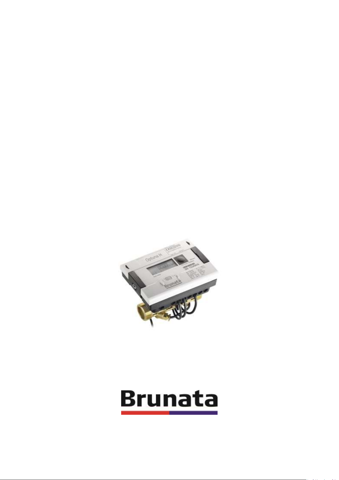
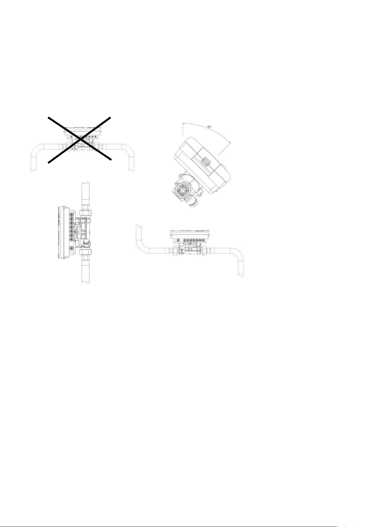
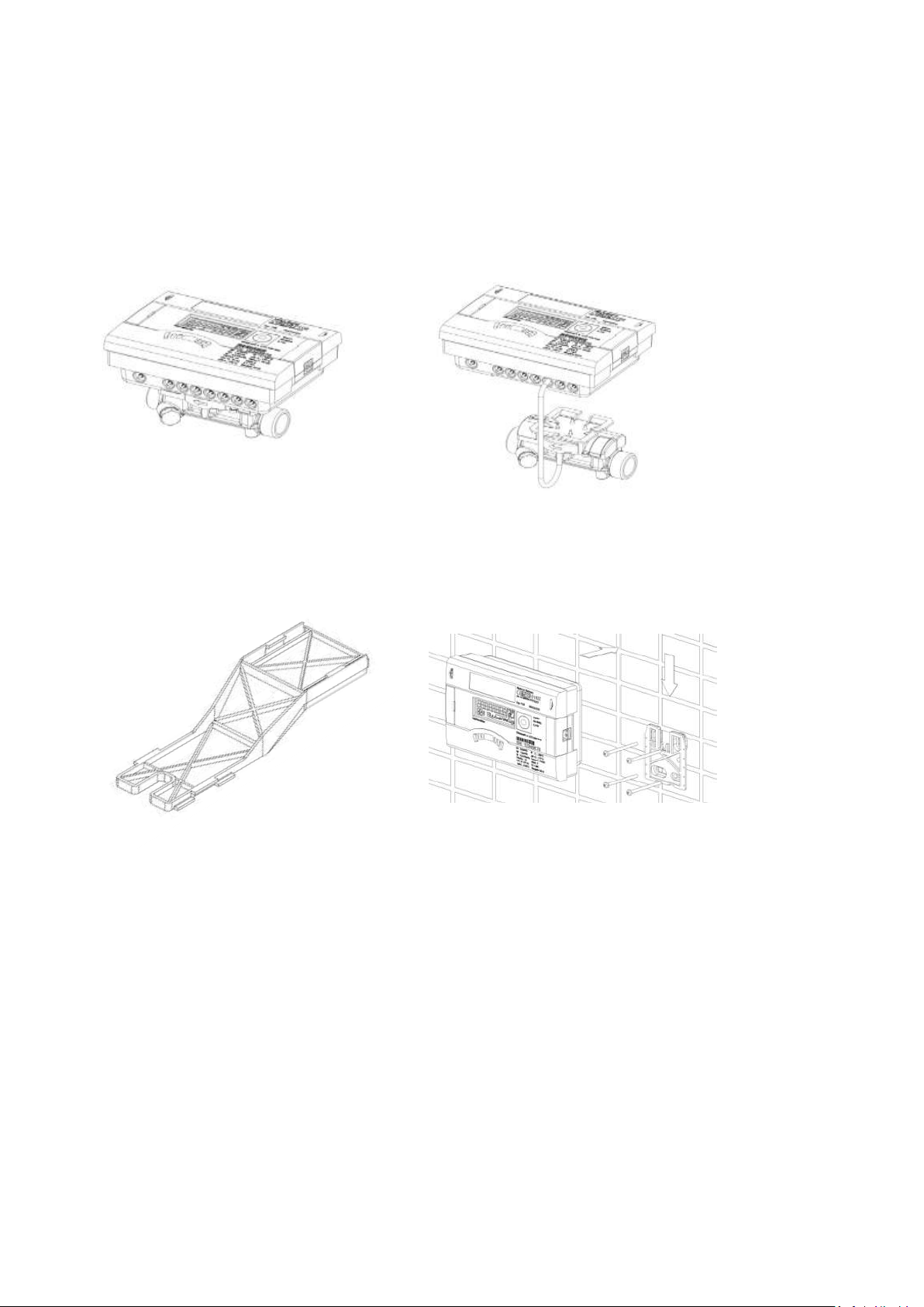
1.2 INSTALLATION OF ENERGY METER ..................................................................................................................................... 3
2.0 INSTALLATION OF TEMPERATURE SENSORS................................................................................................................. 6
3.0 POWER SUPPLY ............................................................................................................................................................. 7
3.1 BATTERY...................................................................................................................................................................... 7
3.2 MAINS UNIT................................................................................................................................................................. 7
4.0 EXTENSION MODULES .................................................................................................................................................. 7
4.1 INSTALLATION OF MODULES ............................................................................................................................................ 8
4.2 COMMUNICATION MODULES ........................................................................................................................................... 8
4.2.1 M-Bus ............................................................................................................................................................... 8
4.2.2 Communication over radio ............................................................................................................................... 9
4.2.3 RS-232 Communication module ....................................................................................................................... 9
4.2.4 RS-485 Communication module ....................................................................................................................... 9
4.3 PULSE INPUT FUNCTION MODULE ................................................................................................................................... 10
4.4 PULSE OUTPUT FUNCTION MODULE................................................................................................................................. 11
4.5 COMBINED FUNCTION MODULE...................................................................................................................................... 12
4.6 ANALOGUE OUTPUT FUNCTION MODULE.......................................................................................................................... 12
4.7 TEST OUTPUT ............................................................................................................................................................. 12
5.0 DISPLAY ....................................................................................................................................................................... 13
5.1 EXPLANATION OF SYMBOLS ........................................................................................................................................... 13
6.0 SIMPLE OPERATION .................................................................................................................................................... 14
6.1 OPERATION INSTRUCTIONS............................................................................................................................................ 14
7.0 ERROR CODES ............................................................................................................................................................. 15
8.0 DECLARATION OF CONFORMITY FOR DEVICES AFTER MID ........................................................................................ 16

Brunata Optuna H UK-QB101575/29.05.2012
Installation Guide Pages 3/16
Brunata a/s · Vesterlundvej 14 · 2730 Herlev · tlf. +45 77 77 70 00 · fax +45 77 77 70 01 · brunat[email protected] · www.brunata.dk
1.0 Introduction
1.1 General
This installation guide is intended for trained personnel and does not contain any basic working steps.
Important!
The seal on the energy meter must not be damaged! A damaged seal will result in immediate invalidation of the
factory warranty and verification. The cables supplied with the meter must not be shortened or changed in any other
way.
Notes!
The regulations on the use of energy meters must be observed!
The meter installation is only to be performed by an installation and/or electrical contractor using personnel trained in
the installation and use of electrical equipment and familiar with the Low Voltage Directive.
Medium: Water without additives.
The specified medium temperature is 5...130 °C (150 °C).
The temperature range depends on variant and nominal size.
The encapsulated variant is to be used if condensation is expected.
The specified operating/ambient conditions are 5 … 55 °C; IP54; 93 % rel. humidity.
Further details about the variants can be obtained from the comprehensive Installation and User Guide. Compliance
with this guide is essential.
1.2 Installation of energy meter
The energy meter should be installed, as indicated in loop 3 in the display, either in the hot or cold line of the system
depending on the design and application (heat, air conditioning or cooling meter).
The meter may only be installed in dry and frost-free areas in buildings.
The flow sensor must be installed so that the direction of flow corresponds to the direction of the arrow on the
sensor.
Ensure that the flow sensor is always filled with liquid during installation.
Calming sections before and after the flow sensor is not necessary.
The meter can be installed in both horizontal and vertical pipe sections, provided air bubbles cannot collect in the
meter. We recommend installing the flow sensor in a tilted position.

Brunata Optuna H UK-QB101575/29.05.2012
Installation Guide Pages 4/16
Brunata a/s · Vesterlundvej 14 · 2730 Herlev · tlf. +45 77 77 70 00 · fax +45 77 77 70 01 · brunat[email protected] · www.brunata.dk
Make sure the meter is installed sufficiently far away from possible sources of electromagnetic interference (switches,
electric motors, fluorescent lamps, etc.).
For medium temperatures of 90 °C or more or if Twater < Tambient (application as cooling meter or heat/cooling meter),
the integrator must be removed from the meter and installed a sufficient distance away from heat sources.
A wall holder (supplied with meter) or a spacer holder (optional) is available for this purpose.
It is recommended that stop valves be fitted before and after the energy meter to simplify removing the meter.
The meter should be installed in a conveniently accessible position for service and operating personnel.
Initial operation is to be carried out and recorded after installation.

Brunata Optuna H UK-QB101575/29.05.2012
Installation Guide Pages 5/16
Brunata a/s · Vesterlundvej 14 · 2730 Herlev · tlf. +45 77 77 70 00 · fax +45 77 77 70 01 · brunat[email protected] · www.brunata.dk
T: 5 … 90°C / Twater > Tambient T: 90 … 130°C/150°C / Twater < Tambient
Spacer holder Wall mounting

Brunata Optuna H UK-QB101575/29.05.2012
Installation Guide Pages 6/16
Brunata a/s · Vesterlundvej 14 · 2730 Herlev · tlf. +45 77 77 70 00 · fax +45 77 77 70 01 · brunat[email protected] · www.brunata.dk
2.0 Installation of temperature sensors
Handle the temperature sensors carefully! The sensor cables are fitted with coloured type labels:
Red: sensor in hot line, blue: sensor in cold line.
The programmed installation location is shown in the information loop.
The free temperature sensor can be installed in a ball valve or in a pocket conforming to the requirements for this
type of sensor. If the sensor is installed in a pocket, it must be inserted as far as the bottom of the pocket and secured.
For installation in a ball valve, a 5-piece coupling set is enclosed in a separate bag. Make sure the sensor is mounted
symmetrically. The connecting cables must not be shortened or extended. The maximum cable length is ten meters.
The sensors should preferably be installed directly immersed. Insert one O-ring in the sensor hole using the mounting
pin supplied. Only tighten the brass or plastic screw by hand (2-3 Nm); tighten the plug screw with a torque of approx.
12 Nm.
1 2 3 4 5.1 5.2 6
Meter type
Sensor marking
Terminal
Installation position
Energy meter in return line
Red
5 Hot 6
Forward
Blue
7 Cold 8
On meter
Energy meter in forward line
Red
5 Hot 6
On meter
Blue
7 Cold 8
Return
Cooling meter in return line
Blue
7 Cold 8
Forward
Red
5 Hot 6
On meter
Cooling meter in forward line
Blue
7 Cold 8
On meter
Red
5 Hot 6
Return
Air conditioning meter in return line
Red
5 Hot 6
Forward
Blue
7 Cold 8
On meter
Air conditioning meter in forward line
Red
5 Hot 6
On meter
Blue
7 Cold 8
Return

Brunata Optuna H UK-QB101575/29.05.2012
Installation Guide Pages 7/16
Brunata a/s · Vesterlundvej 14 · 2730 Herlev · tlf. +45 77 77 70 00 · fax +45 77 77 70 01 · brunat[email protected] · www.brunata.dk
3.0 Power supply
3.1 Battery
A 3.6 V DC lithium battery is fitted in the standard version. The battery is not to be charged or short-circuited. Ambient
temperatures below 40 °C extend the life of the battery. Used batteries must be disposed of at suitable waste
collection points! Caution: Risk of explosion if battery is replaced by an incorrect type.
3.2 Mains unit
24 V AC or 230 V AC mains units (Protection Class 1) can be changed or retrofitted at any time. The protective safety
cover must be installed at all times. Never connect between two phases, as this would destroy the mains unit. The
cable is to be fused at max. 6 A and protected against manipulation.
The mains unit notifies the meter if mains voltage is present. If the mains fail, the backup battery (CR2032) in the
mains unit provides the power supply for up to one year. The LCD readings (on pressing button) and the date and time
are still updated, but none of the measuring functions work, incl. the flow rate measurement. Communication still
functions over the optional M-Bus, RS485 and RS232 modules or the optical interface, but reduces the life of the
backup battery. The radio function is switched off in the event of mains failure.
4.0 Extension modules
The energy meter has two slots for extension modules.
Slot 1
Slot 2
- Pulse In (2x)
- Pulse In (2x)/Out (1x)
- RS232
- M-Bus
- RS485
- L-BUS (for ext. radio)
- Analogue Out (2x)
- Pulse In (2x)
- Pulse Out (2x)
- Pulse In (2x)/Out (1x)
- RS232
- M-Bus
- RS485
- L-BUS (for ext. radio)
The modules can be used and combined as shown in the above table. Use of combinations not
included in the above table is not allowed. With radio meters the slot 2 of the communication
modules has to be left empty. These modules have no effect on consumption recording and can be
fitted retrospectively without damaging the verification mark. The relevant ESD regulations
(electrostatic discharge) must be observed. No liability is accepted for damage (especially to electronic circuits)
resulting from failure to comply with the ESD regulations.

Brunata Optuna H UK-QB101575/29.05.2012
Installation Guide Pages 8/16
Brunata a/s · Vesterlundvej 14 · 2730 Herlev · tlf. +45 77 77 70 00 · fax +45 77 77 70 01 · brunat[email protected] · www.brunata.dk
4.1 Installation of modules
1. Open the integrator by releasing the side catches.
2. Engage the module in the relevant slot and carefully connect the pre-formed ribbon cable at both ends.
3. Close the lid and check the meter for correct operation by pressing the push button. Renew the seal of the
housing lid if the meter functions correctly.
4.2 Communication modules
The meter supports two communication channels over the same or different interfaces. An additional communication
module can be used in radio operation. The protocol is different for each of the two channels and is preset ex works,
but can be set to customer-specific requirements using the IZAR@Set software. Each channel has its own primary
address, but only one secondary address exists, which is set to the serial number ex works.
4.2.1 M-Bus
The M-Bus communication module is a serial interface for communication with external devices (M-Bus control
centre), e.g. IZAR@CENTER. A number of meters can be connected to a control centre. The module contains a 2-pole
terminal strip with terminals marked 24, 25.
The connection is not polarity-conscious and is electrically isolated
M-Bus protocol to EN 1434-3 standard
300 or 2400 bauds (auto baud detect)
Connection for 2 x 2.5 mm² wires
Current drawn: one M-Bus load
Test output
Slot 1
Slot 2
Attention!
Keep free at radio
version

Brunata Optuna H UK-QB101575/29.05.2012
Installation Guide Pages 9/16
Brunata a/s · Vesterlundvej 14 · 2730 Herlev · tlf. +45 77 77 70 00 · fax +45 77 77 70 01 · brunat[email protected] · www.brunata.dk
4.2.2 Communication over radio
The integrated radio module is an interface for communication with Hydrometer radio receivers. Unidirectional
communication has the following specification:
The module sends every 6 ... 25 s (variable, depending on protocol length)
The radio module always accesses the current meter registers
Transmission frequency: 868 MHz
Various Hydrometer receivers are available for receiving the protocol (e.g. Bluetooth, GPRS, LAN, …)
The protocol corresponds to the Open Metering or HYD standard and is encrypted
Reading modes: Brunata DriveBy, Brunata LiveNetwork
4.2.3 RS-232 Communication module
The RS232 communication module is a serial interface for communication with external devices, e.g. PC; 300 or 2400
bauds.
The module contains a 3-pole terminal strip with terminals marked 62(Dat), 63(Req) and 64(GND). A special adapter
cable is required for connection (order no. 087H0121). The coloured wires are to be connected as shown.
4.2.4 RS-485 Communication module
The RS485 communication module is a serial interface for communication with external devices, e.g. PC; 2400 bauds
only. The module contains a 4-pole terminal strip with terminals marked D+, D- and +12-. The module needs an
external power supply of 12 V DC ±5 V.
62 = brown
63 = white
64 = green

Brunata Optuna H UK-QB101575/29.05.2012
Installation Guide Pages 10/16
Brunata a/s · Vesterlundvej 14 · 2730 Herlev · tlf. +45 77 77 70 00 · fax +45 77 77 70 01 · brunat[email protected] · www.brunata.dk
4.3 Pulse input function module
Module for two additional pulse counters. Pulse input 1 is marked as "I1” and ”┴" and input 2 as "I2” and ”┴".
Pulse inputs are programmable (IZAR@SET) for a value of: 1, 2.5, 10, 25, 100, 250, 1000, 2500 litres per pulse
Possible units are all the energy units available in the meter, the volume unit m³ or no unit
Input frequency is in the range < 8 Hz; min. pulse duration 10 ms
Input resistance 2.2 MΩ; terminal voltage 3 V DC
Data is accumulated separately in registers
Data is readable as IN1 and IN2 in the display and can be transmitted over the communication modules
Cable length up to ten meters

Brunata Optuna H UK-QB101575/29.05.2012
Installation Guide Pages 11/16
Brunata a/s · Vesterlundvej 14 · 2730 Herlev · tlf. +45 77 77 70 00 · fax +45 77 77 70 01 · brunat[email protected] · www.brunata.dk
4.4 Pulse output function module
The module contains connections for two pulse outputs, which can be programmed as desired using the IZAR@SET
software. The outputs are marked on the terminal strip as "O1” and ”┴”or "O2” and ”┴" and in the display as Out1 and
Out2.
External power supply: Vcc = 3 - 30 V DC
Output current ≤20 mA with a residual voltage of ≤0.5 V
Open collector (drain)
Output 1:
oFrequency: ≤ 4 Hz
oPulse duration: 125 ms ±10 %
oPulse break: ≥ 125 ms –10 %
Output 2:
oFrequency: ≤ 100 Hz
oPulse duration/Pulse break ~1:1
Volume pulse value is programmable as desired. (default: last digit in display)
Connection Diagram for pulse output
1:Vcc
2: Pulse
3: GND
4: Pulse Output Module
5: Energy meter
6: External Connection

Brunata Optuna H UK-QB101575/29.05.2012
Installation Guide Pages 12/16
Brunata a/s · Vesterlundvej 14 · 2730 Herlev · tlf. +45 77 77 70 00 · fax +45 77 77 70 01 · brunat[email protected] · www.brunata.dk
4.5 Combined function module
The combined module is equipped with two inputs and one output.
The pulse input specification is the same as 4.3 above.
The pulse output specification is the same as pulse output 1 in 4.4 above, but not electrically isolated.
4.6 Analogue output function module
The module contains connections for two passive analogue outputs, which can be programmed as desired using the
IZAR@SET software. The outputs are marked on the terminal strip as “1” and “2” with the respective polarity “+” and
“–”.
Passive; external power supply: 10…30 V DC
Current loop 4 … 20 mA, where 4 mA = 0 value; 20 mA = programmed max. value
Overload up to 20.5 mA, then fault current
Errors are generated at 3.5 mA or 22.6 mA (programmable)
Output values: power, flow rate, temperatures
4.7 Test output
This test output located on the side is intended for use by test centres.
The manufacturer provides two special cables for this:
Volume test pulses
Energy test pulses
Other specifications (pulse value, pulse duration/break, pulse frequency) can be obtained from the Inspection and
Test Instruction.

Brunata Optuna H UK-QB101575/29.05.2012
Installation Guide Pages 13/16
Brunata a/s · Vesterlundvej 14 · 2730 Herlev · tlf. +45 77 77 70 00 · fax +45 77 77 70 01 · brunat[email protected] · www.brunata.dk
5.0 Display
To show the data generated by the integrator in the display, various windows are provided as loop functions that can
be called up in succession to display the system information associated with each window (e.g. energy amounts,
running days, water amounts, current temperatures, maximum values). The energy meter has six different display
loops:
Main loop, day loop, information loop, pulse input/output loop, tariff loop and month loop.
The window content of each loop can be programmed almost as desired. The various display windows comprise up to
seven displays that change at intervals of 2 –4 seconds. The loops in the display are numbered from 1 to 6 to help the
user find his way around quickly. The main loop is programmed with the current data as default setting, e.g. for
energy, volume and flow rate.
5.1 Explanation of symbols

Brunata Optuna H UK-QB101575/29.05.2012
Installation Guide Pages 14/16
Brunata a/s · Vesterlundvej 14 · 2730 Herlev · tlf. +45 77 77 70 00 · fax +45 77 77 70 01 · brunat[email protected] · www.brunata.dk
6.0 Simple operation
The push button is used to switch through the various displays. The button can be pressed for a short or long time. A
short press of the button (< three seconds) switches to the next display within a loop and a long press (>three
seconds) switches to the next display loop. The “Energy” window (sequence 1.1) in the main loop is the basic display.
The meter automatically switches off the display to save power if the button is not pressed for approx. four minutes
(except in the event of a fault) and returns to the basic display when the button is pressed again. The loop settings can
be programmed to suit customer-specific requirements using the IZAR@SET software.
6.1 Operation instructions
The meter is operated by pressing lightly.
If the push button has not been pressed for approx. 3-4 minutes the display will automatically switch off.

Brunata Optuna H UK-QB101575/29.05.2012
Installation Guide Pages 15/16
Brunata a/s · Vesterlundvej 14 · 2730 Herlev · tlf. +45 77 77 70 00 · fax +45 77 77 70 01 · brunat[email protected] · www.brunata.dk
7.0 Error codes
The error code is displayed in the main loop if an error occurs. All the other windows can still be selected by pressing
the button. The error code display appears again automatically if the button is not pressed for approx. four minutes.
The error display disappears automatically as soon as the cause of the error has been cleared. All errors present longer
than six minutes are saved in the error log.
Error display
Error description
C - 1
Basic parameter error in flash or RAM
E 1
Temperature range exceeds [-19,9 °C...199,9 °C]
Sensor short-circuit, sensor break
E 3**
Forward and return sensor reversed
E 4
Hardware error in ultrasonic measurement
transducer or drive defective or short-circuit
E 5
Communication not possible (too frequent reading)
E 6**
Wrong direction of flow in volume measuring component
E 7
No meaningful ultrasonic receive signal
air in the measuring path
E 8
No primary power supply (only if mains unit used), supply is via backup battery
E 9
Battery almost flat; calculated lifetime expired
E A*
Leakage: pipe break detected
E b*
Leakage: leakage detected in energy meter
E C*
Leakage: leakage pulse input 1
E d*
Leakage: leakage pulse input 2
* optional
** application-dependent

Brunata Optuna H UK-QB101575/29.05.2012
Installation Guide Pages 16/16
Brunata a/s · Vesterlundvej 14 · 2730 Herlev · tlf. +45 77 77 70 00 · fax +45 77 77 70 01 · brunat[email protected] · www.brunata.dk
8.0 Declaration of conformity for devices after MID
These products conform to the essential requirements of the following directives:
EMC Directive (2004/108/EC)
R&TTE Directive (1999/5/EC)
MID Directive (2004/22/EF)
DE-10-MI004-PTB013 DE-10-MI004-PTB003
You can find more information regarding the MID-approval on Brunata’s website: www.brunata.com.
Table of contents
Other Brunata Measuring Instrument manuals