Brunner BKH 5.0 Tunnel 42-66 green User manual

Installation Manual
BKH 5.0 Tunnel
42-66
©2023

CONTENTS
1 Basic informations..................................................................................................... 3
2 Safety precautions..................................................................................................... 3
3 Specified symbols......................................................................................................4
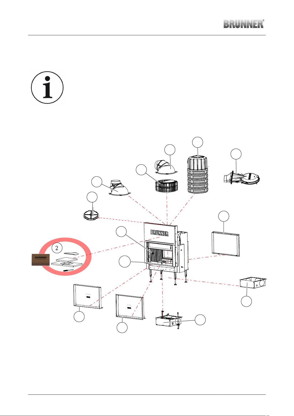
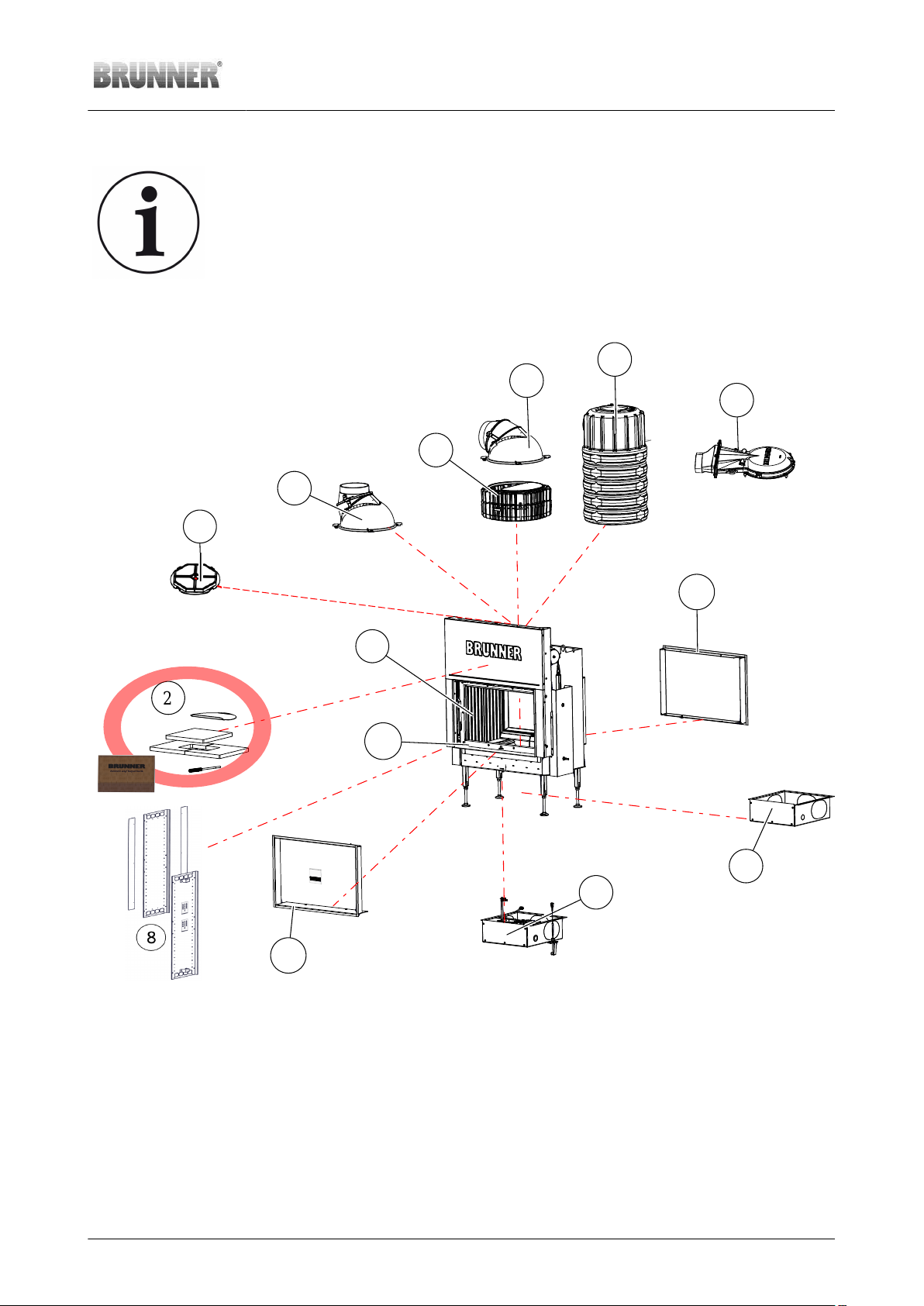
4 Delivery contents BKH 42-66 Tunnel....................................................................... 6
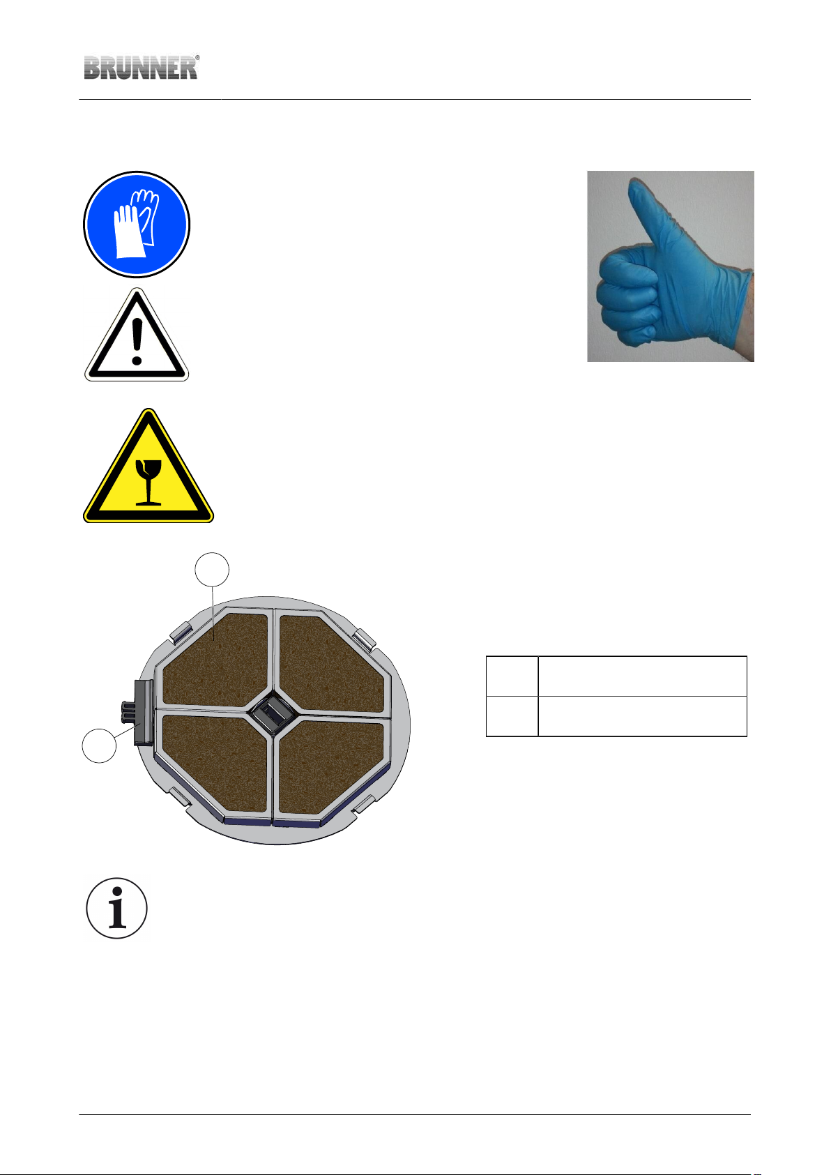
4.1 Catalytic converter (optional)........................................................................................................ 9
4.2 Air connection box (optional)...................................................................................................... 10
4.3 Heat exchanger rings (optional)..................................................................................................10
4.4 Heat protection panel for Tunnel DT-DT.................................................................................... 11
5 Safety distances BKH Tunnel................................................................................. 11
6 Setting up.................................................................................................................. 14
6.1 Remove the transport locks........................................................................................................ 14
6.2 Heat protection panel Tunnel DT-DT..........................................................................................15
6.3 Set up the fireplace.....................................................................................................................22
6.4 Variant with external combustion air connection........................................................................ 24
6.4.1 Bottom connection (B).................................................................................................. 26
6.4.2 Side connection (S)...................................................................................................... 32
7 Variant with EAS or EOS.........................................................................................37
8 Fitting: catalytic converter...................................................................................... 48
9 Fitting: deflection combustion chamber - Tunnel................................................ 52
10 Variants heat exchanger..........................................................................................61
10.1 Connection with catalytic converter............................................................................................ 61
10.2 Connection without catalytic converter....................................................................................... 62
10.3 Heat exchanger - cast iron dome............................................................................................... 66
10.4 Heat exchanger rings.................................................................................................................. 69
10.5 Heat exchanger - MAS............................................................................................................... 75
11 Frame variants..........................................................................................................83
12 Conversions, settings..............................................................................................87
12.1 Change: door hinge.....................................................................................................................87
12.2 Adjusting of self-closing door.................................................................................................... 100
12.3 Modification - lifting door: “non self closing”............................................................................. 108
13 Disposal...................................................................................................................111
14 Technical data........................................................................................................ 112
2 Installation Manual BKH 5.0 Tunnel 42-66 green (1.11) © 2023 Brunner GmbH

1 BASIC INFORMATIONS
All instructions delivered with products must be observed. We do not accept any warranty claim or
liability for damage resulting from failure to observe these installation instructions!
Improper installation can cause injury and material damage!
The floor space of the room must have a suitable structure and sufficient dimensions to ensure proper func-
tioning of the fireplace.
Please note that other installation and assembly instructions are included in other packaging units!
Dimensioning of downstream heat accumulator must be according to valid stove-setting rules.
During installation of the fireplace, all dimensions and minimal clearances of the fireplace casing must be
held as specified by the manufacturer.
All binding national or EU standards and local regulations for the installation of fireplaces must be observed.
All valid stove fitting rules and regulations of local construction law must be observed and followed.
Please follow the relevant regulations of your country.
When these instructions are followed and all works are done properly, this will ensure a safe, energy-sav-
ing and environmentally friendly operation of the stove. Pictures shown are not to be considered as complete
representations of any kind.
Subject to technical and assortment changes.
Please notify your supplier of any damage which might have occurred during transport.
Please keep these instructions.
Please also take note of the online product documentation provided
by:
General instructions of the Brunner products installation for the
stove construction.
(https://www.brunner.de/produktdownloads/kacheloefen-kamine/allge-
meine-hinweise-fuer-den-aufbau_de.pdf) laden können.
2 SAFETY PRECAUTIONS
Fireplaces may be set up only in rooms or areas with no risk of danger due to their location, structure or in-
tended use.
Working on the stove Installation, commissioning, servicing and maintenance works on the
product may be carried out only by an authorized stove-fitter. Safety
and efficiency of the system depend on this!
Working with electronics Switch off the emergency switch or circuit breaker, and secure them
against switching on again.
© 2023 Brunner GmbH Installation Manual BKH 5.0 Tunnel 42-66 green (1.11) 3

Fireplaces with external air supply are not independent from room air supply and must be consid-
ered and designed as roomsealed fireplaces. In connection with a ventilation or extraction system,
we recommend the use of a negative pressure safety device (Art.No.: 11600.1).
Installation must be carried out by an authorized stove-fitter, because safety and efficiency of the system de-
pend mostly on proper installation of the product. All valid stove fitting rules and regulations of building law
must be observed and followed. Make sure to instruct the owner or user about the functions and controls of
the system and possibly installed safety devices.
Fireplaces must be built to ensure safe operation and fire safety in order to eliminate possible risks and un-
acceptable loads. They have to be ready for use over an adequate period of time.
Make sure to instruct the owner or user about the functions and controls of the system and possibly installed
safety devices.
Remember to use only genuine replacement parts.
3 SPECIFIED SYMBOLS
In this documentation, a distinction is made between:
Operating personnel as the User of the system, i.e. the end user, which has received instructions from the Contractor
and does not necessarily have additional qualifications.
Operating personnel as the Contractor, i.e. the qualified professionals, which are entitled to perform the indicated spe-
cialist works.
In this document, the following symbols are used:
DANGER
A danger of high risk persists, which leads to severe injury or death, if this endangering situa-
tion is not avoided.
WARNING
A danger of medium risk persists, which can lead to severe injury or death, if this endangering
situation is not avoided.
CAUTION
A danger of low risk persists, which can lead to minor or moderate injury, if this endangering
situation is not avoided.
ATTENTION
There is a certain risk, which can lead to a malfunction or damage of the related system and all
devices connected with it, if the indicated notifications are not followed.
4 Installation Manual BKH 5.0 Tunnel 42-66 green (1.11) © 2023 Brunner GmbH

NOTE
Additional helpful information
© 2023 Brunner GmbH Installation Manual BKH 5.0 Tunnel 42-66 green (1.11) 5

4 DELIVERY CONTENTS BKH 42-66 TUNNEL
Available variants with lifting door and side-opening door (ST/DT)
Attention: Tunnel inserts can only be operated on one side, the other side is
equipped with an inspection handle. With the EAS version, only one door contact
switch is installed on the operating side.
With ST-DT the ST side is therefore the operable side.
2
7.1
4
5.1
5.4
5.3
3
1
5.2
5.1
7.2 6.2
6.1
7.3
6 Installation Manual BKH 5.0 Tunnel 42-66 green (1.11) © 2023 Brunner GmbH

Available variants with side-opening door and side-opening door (DT/DT)
Attention: Tunnel inserts can only be operated on one side, the other side is
equipped with an inspection handle. With the EAS version, only one door contact
switch is installed on the operating side.
2
7.1
4
5.1
5.4
5.3
3
1
7.1
5.2
5.1
6.2
6.1
© 2023 Brunner GmbH Installation Manual BKH 5.0 Tunnel 42-66 green (1.11) 7

Designation Art. No.
Pos.
BKH - variants: for ST/DT for DT/DT
BKH 5.0 Tunnel 42-66 with manual operation , Ceramic glass
(GK)Chamotte inner linging (FR) HK013002-01 HK014002-01
BKH 5.0 Tunnel 42-66 with manual operation,, Glass ceramic
coated (GKB)Chamotte inner linging (FR) HK013002-05 HK014002-05
BKH 5.0 Tunnel 42-66 for EAS/EOS, Ceramic glass (GK)
Chamotte inner linging (FR) HK013002-02 HK014002-02
BKH 5.0 Tunnel 42-66 for EAS/EOS, Glass ceramic coated
(GKB) Chamotte inner linging (FR) HK013002-06 HK014002-06
BKH 5.0 Tunnel 42-66, with manual operation,, Ceramic
glass (GK) Cast iron inner lining (FR/Guss) HK013002-03 HK014002-03
BKH 5.0 Tunnel 42-66 with manual operation,, Glass ceramic
coated (GKB) Cast iron inner lining (FR/Guss) HK013002-07 HK014002-07
BKH 5.0 Tunnel 42-66 for EAS/EOS, Ceramic glass (GK)
Cast iron inner lining (FR/Guss) HK013002-04 HK014002-04
1
BKH 5.0 Tunnel 42-66 for EAS/EOS, Glass ceramic coated
(GKB) Cast iron inner lining (FR/Guss) HK013002-08 HK014002-08
2The non-installed parts (e.g. deflection plates, control levers, etc.) and any accessories ordered (e.g. catalytic
converter, packaging with EOS, etc.), including the instructions box, are packed in the combustion chamber
3Combustion chamber lining: - made of chamotte or - made of cast iron
4 Catalyst module BKH 5.0 HK000210
Smoke hood variants
Rotating cast iron dome with adjustable connecting piece ⌀
180 mm D004186
5.1
Rotating cast iron dome with connecting piece d=200 mm 10087
5.2 with heat exchanger rings R015006-02
5.3 Connection variant MAS SET440 SET211444
5.4 Cast iron dome low D016042
Additional options
Supply air connection box ⌀ 125 mm HK000135
6.1
Supply air connection box ⌀ 150 mm HK000136
6.2 Supply air connection box ⌀ 125 mm with EOS / EAS HK000080
7.1 for side-opening door HK004150-01 HK004150-01
7.2
Door frame, black
for lifting door HK005152-01 -
7.3 Mounting frame, black ST 60mm HK005150-01 -
8 Heat protection panel - HK014251
8 Installation Manual BKH 5.0 Tunnel 42-66 green (1.11) © 2023 Brunner GmbH

4.1 CATALYTIC CONVERTER (OPTIONAL)
The catalytic converters are coated with a catalytically ac-
tive layer. This coating can consist of mixed metal oxides
or also of precious metals. In order not to limit the effect
of this catalytically active layer, the catalysts may only be
handled with gloves, preferably with disposable gloves.
In order not to limit the effect of this catalytically active lay-
er, the catalysts may only be handled with gloves, prefer-
ably with disposable gloves.
.
ATTENTION
The catalysts are fragile and must only be handled with care. Avoid bumping and
do not drop the catalytic converter. This could destroy the catalytic converter!
1
2
1 catalytic converter
2 assembly tool
Note
This catalytic converter is suitable for all BKH units (with lifting door, with side opening
door, tunnel, with cast dome, with heat exchanger cast rings and MAS).
This catalytic converter can also be retrofitted.
© 2023 Brunner GmbH Installation Manual BKH 5.0 Tunnel 42-66 green (1.11) 9

4.2 AIR CONNECTION BOX (OPTIONAL)
6
5
4
1
3
2
Pos. Description of use
1 Air connection box - allows the connection of an external
combustion line
2 Cover for air connection box
3 Air connection is welded, connection point for combustion air
line
4 Screw for fixing the respective clamping plate
5* Clamping plate for fixing the external combustion air line on
the side
6* Floor clamping plate for fixing the external combustion air line
to the floor
*both clamp plates are supplied, but only the appropriate one is used.
4.3 HEAT EXCHANGER RINGS (OPTIONAL)
1
3
2
2
1
3
1 separate package (4x threaded rod, 4x hexagon nut)
2 deflection heat exchanger ( 2x)
3 cast iron heat exchanger rings ( 2x)
10 Installation Manual BKH 5.0 Tunnel 42-66 green (1.11) © 2023 Brunner GmbH

4.4 HEAT PROTECTION PANEL FOR TUNNEL DT-DT
Heat protection panel art. No. HK014251
5
2
1
3
4
No. Designation pcs
1* Additions to the heat shield* 2*
*INFO: 1 are only required for BSK !!!
2 Heat protection panel 2
3 Fitting 2
4 Inserting plate 1
5 separate package 2
5 SAFETY DISTANCES BKH TUNNEL
Half-height version
without heat protection panel with heat protection panel
© 2023 Brunner GmbH Installation Manual BKH 5.0 Tunnel 42-66 green (1.11) 11

≥50
≥120
50 ≥
≥3
≥120
≥120
≥50
≥3
≥50
≥30
≥120
U-Wert > 0,4 W/m K
2
≥30
2
≥120
≥5
≥50
≥30
≥120
U-Wert > 0,4 W/m K
2
≥30
≥120
≥18
T1
T1
T1
T1
≥5
≥30
≥6
≥50
U-Wert > 0,4 W/m K
2
≥18
≥50
≥3
≥12
floor/wall/ceiling non-combustible fireplace cladding
wall/ceiling/floor/attachments combustible/to be pro-
tected convection opening
substitute insulation material calcium silicate (Promasil
950-KS) radiation range
heat protection panel (accessories) non-combustible flooring /floor protection pane
All figures in cm
When designing the exhaust system and exhaust pipe, national standards and fire protection regulations must be observed
Floor-to-ceiling version
without heat protection panel with heat protection panel
12 Installation Manual BKH 5.0 Tunnel 42-66 green (1.11) © 2023 Brunner GmbH

≥5
≥30
≥6
≥50
50 ≥
≥3
≥50
≥30
≥120
U-Wert < 0,4 W/m K
2
≥30
≥5
2
≥22
≥40
≥22
≥40
≥120
≥12
U-Wert > 0,4 W/m K
2
≥18
≥50
≥5
≥50
≥30
≥120
U-Wert > 0,4 W/m K
2
≥30
≥120
≥18
≥3
≥3
T1
T1
T1
T1
≥120
≥120
floor/wall/ceiling non-combustible fireplace cladding
wall/ceiling/floor/attachments combustible/to be pro-
tected convection opening
substitute insulation material calcium silicate (Promasil
950-KS) radiation range
heat protection panel (accessories) non-combustible flooring /floor protection pane
All figures in cm
When designing the exhaust system and exhaust pipe, national standards and fire protection regulations must be observed
© 2023 Brunner GmbH Installation Manual BKH 5.0 Tunnel 42-66 green (1.11) 13

6 SETTING UP
DANGER
Possible personal injury and/or property damage caused by improper installa-
tion
Assembly and installation of BKH requires extensive specialist knowledge.
•Assembly and installation works must be performed by authorized professionals.
Danger
Risk of injury caused by heavy loads
Carrying of heavy loads can lead to injuries.
- The equipment should be carried by at least two people.
- Use appropriate carrying aids.
- Keep the transport weight in mind.
As long as the device is on the wooden pallet, it can be transported with a hand truck
or forklift as usual.
6.1 REMOVE THE TRANSPORT LOCKS
Side with side-opening door:
NO TRANSPORT LOCK !
14 Installation Manual BKH 5.0 Tunnel 42-66 green (1.11) © 2023 Brunner GmbH

Side with lifting door
Remove the 3 transport locks !
6.2 HEAT PROTECTION PANEL TUNNEL DT-DT
Hint
If you use heat protection panels, they should be mounted before positioning the fire-
place insert. First mount the heat protection panels, then place the fireplace insert
against the wall.
© 2023 Brunner GmbH Installation Manual BKH 5.0 Tunnel 42-66 green (1.11) 15

CAUTION
Risk of injury from sharp edges!
16 Installation Manual BKH 5.0 Tunnel 42-66 green (1.11) © 2023 Brunner GmbH

Preparatory work
1
© 2023 Brunner GmbH Installation Manual BKH 5.0 Tunnel 42-66 green (1.11) 17

2
18 Installation Manual BKH 5.0 Tunnel 42-66 green (1.11) © 2023 Brunner GmbH

3
1
2
4
1
1 are only required for BSK
© 2023 Brunner GmbH Installation Manual BKH 5.0 Tunnel 42-66 green (1.11) 19

for BKH + BSK : for BKH
32-134
150
A
32-134
150
A
A = max. 1395 A = max. 1665
4
20 Installation Manual BKH 5.0 Tunnel 42-66 green (1.11) © 2023 Brunner GmbH
Table of contents
Popular Wood Stove manuals by other brands

Nordica
Nordica FUTURA Instructions for installation, use and maintenance

Drolet
Drolet Savannah DB03020 Technical data

Burley
Burley Debdale 9104-C Installation instructions & user manual

Pacific energy
Pacific energy ALDERLEA T4 LE Operating and installation instructions

ILD
ILD 2 manual

HWAM
HWAM I 30/65 user manual

hergom
hergom C-16/80 N HF Installation, use and maintenance instructions

Blaze King
Blaze King Royal Guardian RGT-3001 Owner's installation and operation manual

Jøtul
Jøtul F 601 N Installation and operating instructions

Obadiah's Wood Stoves
Obadiah's Wood Stoves 1600 Installation & operation

Enviro
Enviro ASCOT VENTED GAS FIREPLACE HEATER owner's manual

Pacific energy
Pacific energy ALDERLEA T6 Installation & operation guide