Brutus 61024BR User manual

READ AND FOLLOW ALL SAFETY AND OPERATING
INSTRUCTIONS BEFORE USING THIS SAW.
LIRE ET SUIVRE TOUTES
LES DIRECTIVES DE SÉCURITÉ ET D’OPÉRATION AVANT
D’UTILISER CETTE SCIE.
LEA Y SIGA TODAS LAS INSTRUCCIONES
DE FUNCIONAMIENTO Y SEGURIDAD ANTES DE USAR ESTA SIERRA.
TILE SAW
29FG
E200561
Professional 24 in. Tile Saw
OWNER’S MANUAL
Scie à carreaux de 600 mm pro
MANUEL D’UTILISATION
Sierra eléctrica professional de 600 mm
MANUAL DE OPERACIÓN
61024BR
By

FOR YOUR OWN SAFETY, READ
INSTRUCTION MANUAL BEFORE OPERATING SAW.
1. Always wear safety goggles when cutting.
2. Use splash hood for every operation for which it can be used.
3. Disconnect saw before cleaning or changing blade.
4. Do not use any cutting blade with openings and grooves.
Use only continuous rim blades.
5. Replace damaged blade before operating.
6. Do not expose to rain or use in damp locations.
This owner’s manual contains
information necessary to operate
and maintain your Brutus 61024BR
Professional 24 in. Tile Saw safely and
correctly. Please take a few minutes to
familiarize yourself with all the contents
of this manual.
Should you have questions, feel free to
call our Customer Service Department,
toll free at: 866-435-8665. Please do
not contact the retailer.
English .............page 1
LEE ESTA INSTUCCION
MANUAL ANTES DE USA LA SIERRA PARA TU BIEN.
1. Siempre utilice gafas de protección al cortar.
2. Utilice una capota de protección para cada operación en la
cual la puede utilizar.
3. Desconectar la sierra antes de limpiarla o antes de cambiar
el disco de corte.
4. No utilice ningún disco de corte que tenga aperturas o
ranuras. Solamente utilice discos de corte lisos.
5. Reemplace el disco de corte cuando esté dañado.
6. No la exponga a la lluvia o no la utilice en áreas húmedas.
Este manual del usuario, contiene la
información necesaria para operar
y mantener su herramienta Brutus
61024BR Sierra eléctrica profesional
de 600 mm de manera segura y
correcta. Por favor tómese unos minutos
para que usted se familiarice con todos
los contenidos en este manual.
Si tiene alguna pregunta, siéntase libre
de llamar a nuestro Departamento
de Servicio al Cliente, llame gratis
al: 866-435-8665. Por favor no se
contacte con el distribuidor.
Español...........página 28
POUR ASSURER VOTRE
SECURITE, LISEZ LE MOIDE D’EMPLOI AVANT D’UTILISER
LE COUPEUR.
1. Toujours porter des lunettes protectrices pendant la coupe.
2. Utiliser le pare-éclaboussure pour chaque opération dont il
peutêtre utiliser.
3. Débrancher l’outil avant de la nettoyer ou de changer les roues.
4. Ne pas utiliser des roues à couper avec des trous ou creux.
Utiliser seulement des roues à couper lisses.
5. Remplacer les roues à couper endommagés avant de faire
fonctionner l’outil.
6. Ne pas exposer à la pluie ou utiliser dans des endroits humides.
Ce guide d’utilisation contient des
renseignements nécessaire pour
faire fonctionner et pour entretenir
votre scie Brutus 61024BR Scie à
carreaux de 600 mm pro en sécurité et
correctement. Veuillez prendre quelques
minutes pour vous familiarisez avec tout
le contenu de ce manuel.
Au cas où vous auriez des questions,
n’hésitez pas à contacter notre Service
à la Clientèle à l’appel gratuit:
866-435-8665. Ne contactez pas le
revendeur s’il-vous-plaît.
Français ...........page 14

– 1 –
TABLE OF CONTENTS
Limited Warranty ......................1
General Safety Instructions ............ 1-2
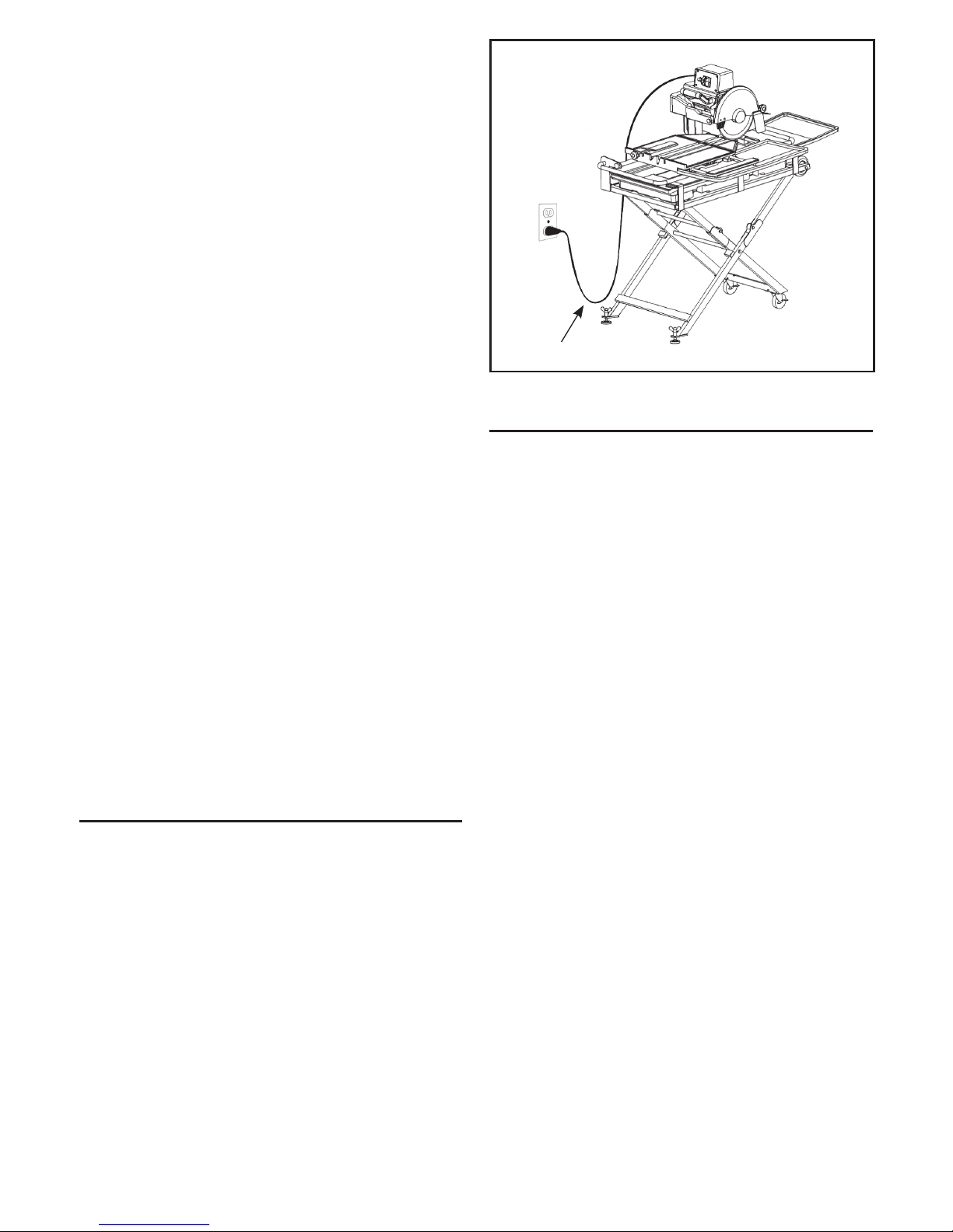
Positioning of Tile Saw..................2
Warning.............................2
California Proposition 65 ................3
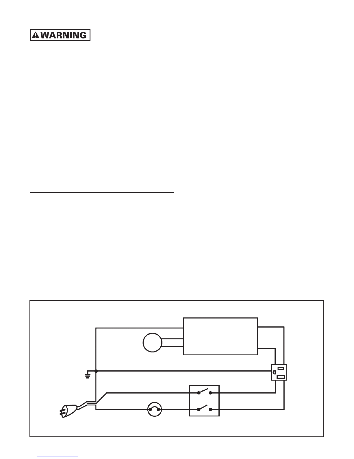
Electrical Requirements ............... 3-4
Extension Cords.......................4
Specific Safety Instructions ..............5
Saw features .........................5
Specifications ........................5
Unpacking ...........................5
Assembly & set up
A. Stand setup .................... 5-6
B. Motor assembly installation ..........6
C. Installing upper frame wheels ........6
D. Installing the cord collecting
hanger/tool caddy .................6
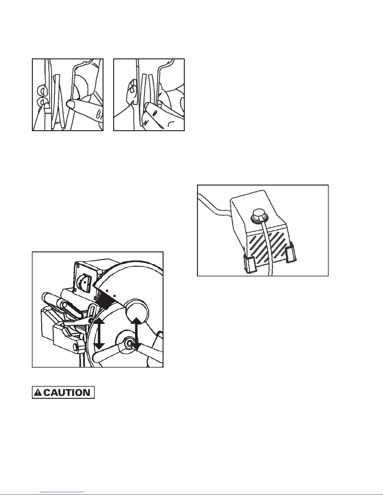
E. Diamond blade installation...........7
F. Water pump installation .............7
G. Rear water collection
tray installation ...................8
H. Extension table installations..........8
Saw operation
Adjustable cutting table extension .......8
Cutting tile and stone.................8
Straight cuts .......................9
Diagonal cuts ......................9
Plunge cuts ........................9
Bevel/miter cuts ................. 9-10
Maintenance
Moving the saw....................10
Cleaning the saw...................10
Water pump maintenance ......... 10-11
Diamond blades....................11
Troubleshooting ......................11
Parts list ...........................12
Exploded parts diagram ................13
LIMITED WARRANTY
Refer to warranty card.
GENERAL SAFETY
INSTRUCTIONS
READ THIS OWNER’S MANUAL
COMPLETELY AND MAKE SURE YOU UNDERSTAND
ALL OF IT’S SAFETY GUIDELINES.
1. KEEP GUARDS IN PLACE and in working order.
2. REMOVE ADJUSTING KEYS AND WRENCHES.
Always check to see that keys and adjusting
wrenches are removed from tool before turning it on.
3. KEEP WORK AREA CLEAN. Cluttered areas and
benches invite accidents.
4. DO NOT USE IN DANGEROUS ENVIRONMENT. Do
not use power tools in damp or wet locations, or
expose them to rain. Keep work area well lighted.
5. KEEP CHILDREN AWAY. All visitors should keep a
safe distance from the work area.
6. MAKE WORKSHOP CHILD PROOF with padlocks,
master switches or by removing starter keys.
7. DO NOT FORCE TOOL. It will do the job better and
be safer at the rate for which it was designed.
8. USE THE RIGHT TOOL. Do not force tool or attach-
ment to do a job for which it was not designed.
9. WEAR PROPER APPAREL. Do not wear loose
clothing, gloves, neckties, rings, bracelets, or other
jewelry which may get caught in moving parts.
Non-slip footwear is recommended. Wear protective
hair covering to contain long hair.
10. ALWAYS USE SAFETY GLASSES. Also use face or
dust mask if cutting operation is dusty. Everyday
eyeglasses only have impact resistant lenses, they
are NOT safety glasses.
11. SECURE WORK. Use clamps or a vise to hold work
when practical. This safety precaution allows for
proper tool operation freeing both hands to operate
tool.
12. DO NOT OVERREACH. Keep proper footing and
balance at all times.
13. MAINTAIN TOOLS WITH CARE. Keep tools sharp
and clean for best and safest performance. Follow
instructions for lubricating and changing acces-
sories.
14. DISCONNECT TOOLS FROM OUTLET before
servicing; when changing accessories, such as
blades, bits, cutters, etc.
15. REDUCE THE RISK OF UNINTENTIONAL STARTING.
Make sure switch is in the “off” position before
plugging in.

– 2 –
Drip loop
FIGURE 1
WARNING
PERSONAL INJURY CAN OCCUR IF OPERATED
IMPROPERLY.
blade.
hands and fingers are clear from the blade groove in
the sliding table. Severe abrasion, cuts, or pinching of
hands or fingers can occur as the table is advanced,
particularly at the end of its travel.
are not followed.
FOR YOUR OWN SAFETY READ INSTRUCTION
MANUAL BEFORE OPERATING SAW.
be used.
wheels, and cleaning.
of openings and grooves.
16. USE RECOMMENDED ACCESSORIES. Consult the
owner’s manual for recommended accessories.
The use of improper accessories may increase risk
of injury.
17. NEVER STAND ON TOOL. Serious injury could
occur if the tool is tipped or if the cutting tool is
unintentionally contacted.
18. CHECK DAMAGED PARTS. Before further use of
the tool, a guard or other part that is damaged
should be carefully checked to determine that
it will operate properly and perform its intended
function – check for alignment of moving parts,
binding of moving parts, breakage of parts,
mounting, and any other conditions that may
affect its operation. A guard or other parts that are
damaged should be properly repaired or replaced.
19. DIRECTION OF FEED. Feed work into a blade
against the direction of rotation of the blade only.
20. NEVER LEAVE THE TOOL RUNNING
UNATTENDED. TURN POWER OFF. Do not leave
tool until it comes to a complete stop.
21. ALWAYS TURN OFF THE POWER while adjusting
the angle for miter cuts.
22. CUTTING TABLE MUST BE IN THE STARTING
POSITION before adjusting the cutting head, to
perform bevel cuts.
23. ENSURE THAT THERE IS A CONTINUOUS FLOW
OF WATER to both sides of the blade during
operation.
24. CHECK DIAMOND BLADES CAREFULLY FOR
CRACKS, NICKS, MISSING DIAMOND MATRIX
OR OUT OF ALIGNMENT CONDITION. Replace
damaged blades immediately. Do not use
damaged blades, which can cause bodily injury.
POSITIONING OF TILE SAW
A. To avoid the possibility of the appliance plug or
receptacle getting wet, position the tile saw to one side
of a wall-mounted receptacle to prevent water from
dripping onto the receptacle or plug. The user should
arrange a “drip loop” is that part of the cord below the
level of the receptacle, or connector if an extension
cord is used, to prevent water traveling along the cord
and coming in contact with the receptacle (FIGURE 1).
B. If the plug or receptacle does get wet, DO NOT
unplug the cord. Disconnect the fuse or circuit breaker
that supplies power to the tool. Then, unplug and
examine for presence of water in the receptacle.

– 3 –
CALIFORNIA PROPOSITION 65
SOME DUST CREATED BY
POWER SANDING, SAWING, GRINDING, DRILLING
AND OTHER CONSTRUCTION ACTIVITIES CONTAIN
CHEMICALS KNOWN TO THE STATE OF CALIFORNIA
TO CAUSE CANCER, BIRTH DEFECTS OR OTHER
REPRODUCTIVE HARM.
Some examples of these chemicals are:
masonry products, and,
lumber.
Your risk from these exposures varies, depending on
how often you do this type of work. To reduce your
exposure to these chemicals: work in well ventilated
area, and work with approved safety equipment, such
as those dust masks that are specifically designed to
filter out microscopic particles.
ELECTRICAL REQUIREMENTS
1. THIS TILE SAW MUST BE CONNECTED TO A
GROUNDED POWER SOURCE while in use to
protect the operator from electrical shock.
2. IN THE EVENT OF A MALFUNCTION OR
BREAKDOWN, grounding provides a path of least
resistance for electrical current to reduce the
risk of electrical shock. This tool is equipped with
an electric cord having equipment grounding
conductor and a grounding plug. Insert the 3-prong
electrical plug into a 3-pole receptacle that is
properly installed and grounded in accordance
with all local codes and ordinances.
3. DO NOT MODIFY THE PLUG provided if it will not
fit the outlet. Have the proper outlet installed by a
qualified electrician.
4. IMPROPER CONNECTION OF THE EqUIPMENT-
GROUNDING CONDUCTOR CAN RESULT IN A
RISK OF ELECTRIC SHOCK. The conductor with
insulation having an outer surface that is green
(with or without yellow stripes) is the equipment-
grounding conductor. If repair or replacement
of the electric cord or plug in necessary, do not
connect the equipment-grounding conductor to a
live terminal.
5. CHECK WITH A qUALIFIED ELECTRICIAN or
service personnel if the grounding instructions
are not completely understood, or if in doubt as to
whether the tool is properly grounded.
6. USE ONLY 3-WIRE EXTENSION CORDS that have
3-prong grounding plugs and 3-pole receptacles
that accept the tool’s plug.
7. REPAIR OR REPLACE DAMAGED OR WORN
CORD IMMEDIATELY.
8. To avoid the possibility of the appliance plug or
receptacle getting wet, POSITION TILE SAW TO
ONE SIDE OF A WALL-MOUNTED RECEPTACLE
TO PREVENT WATER FROM DRIPPING ONTO THE
RECEPTACLE OR PLUG. The user should arrange
a “drip loop” in the cord connecting the saw to a
receptacle. The “drip loop” is that part of the cord
below the level of the receptacle, or the connector
if an extension cord is used, to prevent water
traveling along the cord and coming in contact
with the receptacle.
WIRING DIAGRAM
Green
Green
Black
White
Green
White
White
Black
Black
Black
Overcurrent
breaker Interruptor
Ground
to motor
frame
Capacitor
Motor
FIGURE 2

– 4 –
9. IF THE PLUG OR RECEPTACLE DOES GET WET,
DO NOT UNPLUG THE CORD. Disconnect the fuse
or circuit breaker that supplies power to the tool.
Then unplug and examine for presence of water in
the receptacle.
10. ONLY UL LISTED EXTENSION CORDS SHOULD BE
USED WITH THIS PRODUCT.
11. IMPROPER USE OF EXTENSION CORDS MAY
CAUSE INEFFICIENT OPERATION OF YOUR TOOL,
WHICH CAN RESULT IN OVERHEATING. Be sure
your extension cord is rated to allow sufficient
current flow to the motor. For the proper gauge for
your tool, see chart.
12. DO NOT LET YOUR FINGERS TOUCH THE
TERMINALS OF PLUG when installing or removing
the plug to or from the outlet.
13. THIS TILE SAW MUST BE PROPERLY GROUNDED.
If not properly grounded, this power tool can incur
the potential hazard of electrical shock particularly
when used in damp locations or in proximity to
plumbing. If an electrical shock occurs, there is the
potential of a secondary hazard such as your hands
contacting the saw blade.
14. This tool is intended for use on a circuit that has
an outlet that looks like the one illustrated in
FIGURE 3(B). The tool has a grounding plug that
looks like the plug illustrated in FIGURE 3(A).
The green-colored rigid prongs extending from
the adapter must be connected to a permanent
ground such as a properly grounded outlet box.
Metal
screw
(B) Grounded outlet box
(A) Grounding pin
FIGURE 3
EXTENSION CORDS
outdoor use. These extension cords are identified by
a marking “Acceptable for use with outdoor appli-
ances: store indoors while not in use.” Use only
extension cords having an electrical rating equal
to or greater than the rating of the product. Do not
use damaged extension cords. Examine extension
cord before using and replace if damaged. Do not
abuse extension cords and do not yank on any cord
to disconnect. Keep cord away from heat and sharp
edges. Always disconnect the extension cord from
the receptacle before disconnecting the product from
the extension cord.
TO REDUCE THE RISK OF
ELECTROCUTION, KEEP ALL CONNECTIONS DRY AND
OFF THE GROUND. DO NOT TOUCH PLUG WITH WET
HANDS.
should be provided on the circuit(s) or outlet(s) to
be used for the tile saw. Receptacles are available
having built-in GFCI protection and may be used for
this measure of safety.
cord is in good condition. When using an extension
cord, be sure to use a cord heavy enough to carry
the current your product will draw. An undersized
cord will cause a drop in line voltage, resulting in
loss power and overheating. TABLE 1 shows the
correct size to use depending on cord length and
nameplate ampere rating. If in doubt, use the next
heavier gauge. The smaller the gauge number, the
heavier the cord.
TO AVOID PERMANENT
MOTOR DAMAGE YOU MUST USE THE CORRECT
ExTENSION CORD. NEVER USE MORE THAN ONE
ExTENSION CORD AT A TIME.
Ampere rating Volts Total length of cord in feet
120 V~ 25 ft. 50 ft. 100 ft. 150 ft.
More than No more than AWG
0 6 18 16 16 14
6 10 16 16 14 12
10 12 16 16 14 12
12 16 14 12 Not recommended
TABLE 1

– 5 –
SPECIFICATIONS
03450 RPM
UNPACKING
Open carton from the top.
Top tray contents:
wrenches (2) and 6 mm Allen key
wheel hardware (2), motor frame mounting screws (3),
hardware for mounting tool caddy (2), and motor
frame locking knob]
Middle tray contents:
Bottom tray contents:
ASSEMBLY & SET UP
THE FOLLOWING IS STEP-BY-
STEP INSTALLATION AND OPERATION INSTRUCTION
MANUAL. PLEASE READ THE INFORMATION
THOROUGHLY PRIOR TO USING YOUR TILE SAW.
A. STAND SETUP
The stand is ready to use. Simply unfold it as shown
in FIGURE 4.
Place the saw frame on the stand and tighten the stand
knobs for safety (FIGURE 5). You may need to move
or remove water tray to easily secure safety knobs to
stand frame.
TABLE 1
SPECIFIC SAFETY
INSTRUCTIONS
1. Ensure that the directional arrow marked on the
blade corresponds with the rotational direction of
the motor.
2. With the saw disconnected from the power supply,
rotate the blade by hand to ensure it is free from
obstruction.
3. Always keep the blade-securing arbor and collars
clean.
4. Ensure that the blade-securing bolt is securely
tightened.
5. Never try to cut freehand. Always ensure that the
tile to be cut is pressed firmly against the rip guide.
6. Ensure the material being cut off has sufficient
room to move sideways. Failure to do so may result
in the off-cut binding against the blade.
7. Never cut more than one tile at a time.
8. Never cut pieces too small that are not held securely
against the rip guide, and provide enough space for
the hand to be a safe distance from the blade.
9. Ensure that the table and surrounding area are
clear with the exception of the tile to be cut.
10. Before cutting a tile piece, let the saw blade run
freely for a few seconds. If it makes an unfamiliar
sound or vibrates excessively, switch it off
immediately and disconnect it from the power
supply.
11. Let the blade reach full speed before beginning
the cut.
12. Let the blade come to a complete stop before
removing any jammed material from around the
blade area.
13. Never allow the blade to run dry. Failure to keep
the water tray at the recommended level will result
in possible over-heating of the diamond blade.
SAW FEATURES
22.5° and 45° bevel cuts
— diagonally cuts up to 18 in. tile
well as easy mobility

– 6 –
FIGURE 4
FIGURE 5
B. MOTOR ASSEMBLY INSTALLATION
STEP 1: Install the motor frame assembly into the
motor support arm (FIGURE 6).
STEP 2: Pre-fix the red motor frame locking knob into
the hole provided, as shown. This knob is also used to
fine-tune the alignment of the motor frame assembly.
STEP 3: Remove the rubber cap to expose hex nuts.
Firmly drive the three hex bolts into the motor support
arm with Allen key provided and secure the motor
frame locking knob.
STEP 4: Place rubber cap back over hex nuts.
Motor
frame
locking
knob
Rubber
cap
Motor
support
arm
FIGURE 6
C. INSTALLING UPPER FRAME
WHEELS
Secure the 4 in. wheels at the two ends of the base
frame with hex bolts and nuts, as shown (FIGURE 7).
FIGURE 7
D. INSTALLING THE CORD
COLLECTING HANGER / TOOL CADDY
Secure the hanger onto the motor support arm with 2
bolts (FIGURE 8). Place 2 wrenches in hanger and place
Allen key in opening provided.
FIGURE 8

– 7 –
E. DIAMOND BLADE INSTALLATION
STEP 1: When installing the blade, separate the two
water feed hoses inside the blade guard to allow the
blade to sit between them (FIGURES 9a and 9b).
FIGURE 9A FIGURE 9B
STEP 2: Lift the blade guard and lock in place with the
knob holding the blade guard.
STEP 3: Hold the blade lock nut with the provided
23 mm wrench and also hold the blade shaft with the
other provided 10 mm wrench. At the same time, move
the wrenches upward to loosen or downward to tighten
(FIGURE 10) in order to open and close the blade shaft
nut and outer flange. Then, attach and secure the blade
onto the blade shaft, keeping the inner flange in place.
Place the blade between the two water tubes in the
back of the blade guard.
FIGURE 10
MAKE SURE THAT THE
DIRECTIONAL ARROW ON THE BLADE POINTS IN THE
SAME DIRECTION AS THE ARROW MARKED ON THE
BLADE GUARD FIxING PLATE.
STEP 4: Replace the blade guard to its original position
and tighten knob.
STEP 5: To remove or change the blade, just reverse
the installation steps.
F. WATER PUMP INSTALLATION
STEP 1: Make sure the water pump (see FIGURE 11) is
not cracked or damage in any way.
STEP 2: Attach the end of the tube to the pump nipple
and L-shaped water flow at the back of blade guard.
STEP 3: Place the pump at the location in the water
tray that has been designed to secure the pump during
use.
STEP 4: Pour the water into the water tray and make
sure the water level is higher than the pump intake
nozzle.
STEP 5: Keep the power cord end out of water and
plug the power cord into the 3-prong receptacle on
the side of the cutting head assembly. The pump is
activated by the ON/OFF switch of the tile saw.
STEP 6: Make sure that the water valve connecting the
pump to the tubing is in the full open position.
FIGURE 11
NOTE: THE FOLLOWING ARE WATER PUMP SAFETY
GUIDELINES
receptacle to prevent the electric shock.
reduce any chance of pump damage.
hand, or when standing on a wet surface.
especially gasoline, kerosene, or other combustible
or corrosive liquids.
-
necting the power source if the pump fails to operate.
needs water to cool its own motor. A dry pump may
cause damage or danger.

– 8 –
ADJUSTABLE CUTTING TABLE
EXTENSION
The adjustable cutting extension table is for the support
of large format tiles. Users can adjust front and side
extension to desired dimension (Figure 14).
FIGURE 14
CUTTING TILE AND STONE
BEFORE PERFORMING ANY
CUTS, CHECK AND ENSURE THAT THE LOWEST
POINT OF THE BLADE IS NO MORE THAN 3/16 INCH
(5 MM) BELOW THE TABLE TOP (FIGURE 15).
3/6 in.
(5 mm)
Blade
Surface of working table
Blade
rim
FIGURE 15
Move the motor head height adjustment lever upward
(FIGURE 16), to adjust the head to a proper height below
the table. Then lock the lever in the down position.
Motor head height
adjustment lever
FIGURE 16
G. REAR WATER COLLECTION
TRAY INSTALLATION
Insert and attach the rear water collection tray to the
main water tray at the corresponding joints (FIGURE 12).
FIGURE 12
H. EXTENSION TABLE INSTALLATIONS
Front extension table: Place the extension table in the
back of the main working table. Secure the extension table
with the supplied round cap hex bolts (FIGURE 13).
Side extension table: Insert the side extension table
tubes into the side tunnels at front and back of the
main working table. Insert the pins at the ends of side
extension table tubes to hold them in place (FIGURE 13).
FIGURE 13
SAW OPERATION
DO NOT ADJUST THE SAW
WITHOUT FIRST TURNING OFF THE MOTOR. FAILURE
TO DO SO MAY RESULT IN SERIOUS INJURY TO THE
OPERATOR.
ALWAYS KEEP THE SAW
CLEAR. NEVER PUT THINGS ON RAIL WHILE
CUTTING.

– 9 –
STRAIGhT CUTS
STEP 1: Adjust the rip guide to 90°and position it the
desired distance from the blade.
STEP 2: Position the material to be cut against the rip
guide and back measurement rail.
STEP 3: Loosen the slide tube locking knob (FIGURE 17).
STEP 4: Make a straight cut by pushing the cutting
table toward the cutting head (FIGURE 18).
Slide tube
locking knob
FIGURE 17
Rip
guide
FIGURE 18
DIAGONAL CUTS
STEP 1: Adjust the rip guide to 45° and position it at
the desired distance from the blade.
STEP 2: Position the material to be cut against the rip
guide and back measurement rail.
STEP 3: Loosen the slide tube locking knob (FIGURE 17).
STEP 4: Make a diagonal cut by pushing the cutting
table toward the cutting head (FIGURE 19).
Rip
guide
FIGURE 19
PLUNGE CUTS
TURN OFF THE POWER BEFORE
ADJUSTING THE TILE SAW MOTOR HEAD FOR PLUNGE
CUTS OR BEVEL CUTS.
STEP 1: Turn off the power.
STEP 2: Position the material to be cut against the rip
guide and back measurement rail.
STEP 3: Loosen the slide tube locking knob (FIGURE 17).
STEP 4: Loosen the motor head adjustment lever on the
spring support (FIGURE 16), to release the cutting head.
STEP 5: Bring motor head to the highest position.
STEP 6: Push the cutting table to the desired position
where the blade is over the tile at the point you want to
start the cut-out.
STEP 7: Tighten the slide tube locking knob to a fixed
table position.
STEP 8: Turn the saw on.
STEP 9: Slowly push the blade down into the tile to
achieve the plunge internal cut you desire (FIGURE 20).
STEP 10: After each cut, turn the motor off and turn
the position of the tile to achieve rectangle or square
cut-outs.
Rip
guide
FIGURE 20
BEvEL/MITER CUTS
THE SAW IS ADJUSTABLE TO
THREE POSITIONS (0°, 22.5 °OR 45°). ANY OTHER
BEVEL CUT WILL DAMAGE THE WORK TABLE.
STEP 1: Turn off the power.
STEP 2: Position the cutting table in its farthest back
position and lock with slide tube locking knob
(FIGURE 17).
STEP 3: Loosen the bevel adjustable knob on the bevel
support arm (FIGURE 21), found at the back of the motor
head, to adjust the guide by tilting the head (FIGURE 22)
to 22.5° or 45°angle. Make sure the blade aligns with
the angle slot provided on the cutting table.

– 10 –
STEP 4: Tighten the bevel adjustable knob when the
cutting head is positioned on the desired angle.
STEP 5: Turn on the power and make bevel cuts by
pushing the cutting table toward the cutting head.
Bevel
adjustable
knob
45°–90°
FIGURE 21
FIGURE 22
MAINTENANCE
DO NOT SERVICE, CLEAN, OR
MAINTAIN THE SAW WITHOUT FIRST TURNING OFF
THE MOTOR AND UNPLUGGING THE SAW FROM ITS
POWER SOURCE. FAILURE TO DO SO MAY RESULT IN
SERIOUS INJURY TO THE OPERATOR.
MOvING ThE SAW
Before moving the saw, be sure to tighten the
slide tube locking knob (FIGURE 17), to prevent main
working table from sliding randomly during transport.
site, unlock the wheels on the bottom of the stand and
move the saw with the stand attached.
saw from the stand and use the wheels on the saw
frame (FIGURE 23). The stand folds up separately for
easy transport (FIGURE 24).
FIGURE 23
FIGURE 24
CLEANING ThE SAW
For the long life and best performance of saw:
clean and free of debris.
overheating.
side extension table tubes after each use.
NOTE: NEVER attempt to service the internal parts of
the motor. Contact our company’s Customer Service
Department for any motor function problems or failures.
WATER PUMP MAINTENANCE
DISCONNECT THE POWER
BEFORE MAINTENANCE OF THE PUMP.
1. Disassemble the water pump to see if any cracks or
dirt are inside (FIGURE 25).
2. Check if the water tubing is clogged where the water
cannot flow. Clear the tubing with warm water.
3. Make sure pump is plugged in during use.

– 11 –
ALWAYS WEAR PROPER SAFETY EQUIPMENT at all
times when operating the saw. Wear goggles and
dust mask at all times when operating saw.
ALWAYS ENSURE A CONTINUOUS FLOW OF WATER on
both sides of the blade before cutting any material.
GUARDS IN POSITION.
OR SMALLER THAN RECOMMENDED.
DO NOT EXCEED MAXIMUM RPMS recommended by
the blade manufacturer.
DO NOT FORCE THE MATERIAL into the blade. Let the
blade cut at its own speed.
BLADE MANUFACTURER.
TROUBLESHOOTING
IF THE SAW IS OVERHEATING:
touch.
blockage and dirt.
IF THE SAW DOES NOT START:
outlet.
IF WATER IS NOT FLOWING THROUGH THE
WATER PUMP:
intake nozzle.
the tubing is in the “ON” position.
IF THE CUTTING TABLE IS NOT SLIDING SMOOTHLY:
guide rails.
If problem continues, call our Customer Service
Department at 1-866-435-8665.
4. Make sure the in-take sponge filter is cleaned after
each use.
5. Pump clean/ fresh water for one minute through the
water pump and the blade guard to prevent waste
build-up and clogging.
Do not run the pump without water.
Front plate
accessory
Sponge
Impeller
lid Pump
shaft
Impeller
FIGURE 25
DIAMOND BLADES
1. Use only 10 in. wet continuous rim diamond blade
with this saw.
2. Arbor size is 5/8 in.—please choose the right size to
fit the inner flange.
3. Do not use wood sawing blade, or other blades not
suitable for ceramic, porcelain or stone—severe
body injury or the saw damage may occur.
4. This saw comes with a standard blade that is ideal
for cutting ceramic tile. If your project requires the
cutting of other substrates (ex. porcelain, slate,
stone), it is recommended that you use the specific
type of blade for the material being cut.
THE FOLLOWING ARE DIAMOND BLADE SAFETY
PRECAUTIONS:
for cracks or uneven wear.
Discard cracked, chipped or bent blades!
ALWAYS USE MANUFACTURER’S RECOMMENDATION
for matching the right blade with the right material
being cut.
INSPECT THE ARBOR SHAFT for uneven wear before
mounting the blade.
ALWAYS USE BLADES WITH THE CORRECT ARBOR
SIZE on a compatible arbor shaft.
ENSURE THE BLADE IS MOUNTED WITH THE
ROTATION ARROW IN THE PROPER DIRECTION and is
securely tightened with a wrench.

– 12 –
EXPLODED PARTS DIAGRAM
6-1003Q

– 13 –
PART LIST
PART # DESCRIPTION
61024-01 Blade lock nut
61024-02 Outer flange
6-1003Q Blade
61024-04 Inner flange
61024-05 Blade guard fixing knob
61024-06 Blade guard
61024-07 Water brush (2)
61024-08 Screw
61024-09 Flat washer
61024-10 Y-water feed
61024-11 Phillips screw M5X16
61024-12 Water tube splitter plate
61024-13 Splash guard
61024-14 Phillips screw M4X12 (8)
61024-15 Flat washer (8)
61024-16 Blade guard shaft
61024-17 Plunge adjusting lever
61024-18 Wave-shaped bushing
61024-19 Teeth-surface nut
61024-20 Flat washer
61024-21 Motor head handle
61024-22 Motor
61024-23 Switch
61024-24 Receptacle socket
61024-25 Power cord
61024-26 Bevel hinge shaft
61024-27 Plunge adjusting plate
61024-28 Screw (2)
61024-29 Washer plate (2)
61024-30 Spring washer (2)
61024-31 Motor frame
61024-32 Bearings (2)
61024-33 Plunge counterforce spring
61024-34 Plunge shaft
61024-35 Hex screw (2)
61024-36 Phillips screw (square neck)
M8X40
61024-37 Bevel angle marking plate
61024-38 Pointer
61024-39 Bevel cut adjustment knob
PART # DESCRIPTION
61024-40 Bevel hinge shaft
61024-41 Hex socket cap screw (3)
61024-42 Motor frame locking knob
61024-43 Cord collecting hanger
61024-44 Cord collecting hanger
cover plate
61024-45 Screw (2)
61024-46 Motor support arm
61024-47 Hex socket cap screw
61024-48 Lock nut (2)
61024-49 Flat washer (2)
61024-50 Spring washer (2)
61024-51 Hex screw (2)
61024-52 Hex socket cap screw
M10X12
61024-53 Motor support arm washer
61024-54 Hex screw (2)
61024-55 Teeth – surfaced washer (2)
61024-56 Flat washer (2)
61024-57 4 in. base frame caster (2)
61024-58 Hex screw (2)
61024-59 Self locking nut M8 (2)
61024-60 Base frame
61024-61 Working table sliding rail
61024-62 Slide tube assembly (2)
61024-63 Grease injection fitting
61024-64 Sliding tube locking knob
61024-65 Sliding tube
61024-66 Hex screw (2)
61024-67 Working table pad
61024-68 Overload switch
61024-69 Work table
61024-70 Back extension working table
61024-71 Pin (2)
61024-72 Back extension working
table pad
61024-73 Roller fixing plate
61024-74 Hex socket cap screw
M8X22 (4)
61024-75 Nylon roller (2)
61024-76 Flat washer (13)
PART # DESCRIPTION
61024-77 Hex screw (2)
61024-78 Side extension table tube
bushing (2)
61024-79 Side extension table tube (2)
61024-80 Hex socket cap screw
M5X10 (2)
61024-81 Side extension table
61024-82 Side extension table pad
61024-83 Water tray
61024-84 Tank drainage plug
61024-85 Phillips screw M6X20 (2)
61024-86 Stand knob (2)
61024-87 Saw stand
61024-88 Sliding tube end seal (2)
61024-89 Extension water tray
61024-90 Motor shaft wrench
61024-91 Wrench for loosening nut
61024-92 Allen wrench
60095 Water pump
61024-94 Rip guide
61024-95 Rip guide locking knob
61024-96 Spring washer (13)
61024-97 Self tapping screw (4)
61024-98 Motor shaft bushing
61024-99 Sealing
61024-100 Capacitor
61024-101 Thin nut (2)
61024-102 Flat washer
61024-103 Flat washer
61024-104 Water tube clip

– 14 –
TABLE DES MATIÈRES
Garantie limitée ......................14
Règles générales sur la sécurité ..... 14 - 15
Positionnement de la sci ...............15
Avertissement ................... 15 - 16
Proposition 65 de la Californie ...........16
Installations électriques ............ 16 - 17
Rallonges électriques.............. 17 - 18
Guide de sécurité spécifique ............18
Caractéristiques de la scie..............18
Spécifications .......................18
Déballage ...................... 18 - 19
Assemblage et installation
A. Installation de support .............19
B. Installation du monture du moteur ....19
C. Installation de la roue pour
cadre supérieur..................20
D. Installation du crochet pour tenir
le cordon/boîte à outils ............20
E. Installation de la lame diamantée.....20
F. Installation de la pompe d’eau .......21
G. Installation du plateau
collectrice d’eau arrière............21
H. Installations de tables d'extension ....21
Utilisation de la scie
Table à allonge de coupe réglable ......22
Pour couper les carreaux et la pierre ....22
Coupe droite ......................22
Coupe en diagonale.................23
Coupe en plonger ..................23
Coupe en biseau/à onglet ........ 23 - 24
Entretien
Transporter la scie..................24
Nettoyage de la scie ................24
Entretien de la pompe d’eau ...... 24 - 25
Lames diamantées .................25
Dépannages ........................25
Pièces éclatées ......................26
Liste des pièces......................27
GARANTIE LIMITÉE
Faire référence à la carte de guarantie.
RÈGLES GÉNÉRALES
SUR LA SÉCURITÉ
LIRE CE MANUEL
D’UTILISATION AU COMPLET ET S’ASSURER DE BIEN
COMPRENDRE TOUTES LES CONSIGNES DE SÉCURITÉ.
1. GARDEZ LES DISPOSITIFS DE PROTECTION EN
PLACE et en bon état de marche.
2. RETIREZ LES CLÉS D’AJUSTEMENT ET LES CLÉS
À MOLETTE. Vérifiez toujours que les clés
d’ajustement et à molette sont retirées de la scie
avant de la mettre en marche.
3. GARDEZ L’AIRE DE TRAVAIL PROPRE. Les
endroits et les établis qui ont des fouillis attirent
les accidents.
4. N’UTILISEZ PAS DANS UN MILIEU DANGEREUX.
N’utilisez pas les outils électriques dans des
endroits humides ou mouillés et ne l’exposez pas à
la pluie. Gardez l’aire de travail bien éclairé.
5. GARDEZ LES ENFANTS À DISTANCE. Gardez tous
les visiteurs à une distance sans danger de l’aire
de travail.
6. RENDEZ VOTRE ATELIER SANS DANGER POUR
LES ENFANTS avec des cadenas, des interrupteurs
généraux ou en retirant les clés de démarrage.
7. NE FORCEZ PAS LA SCIE. Elle fonctionnera mieux
et sera plus sécuritaire à la vitesse prévue.
8. UTILISEZ LA SCIE CORRECTEMENT. Ne forcez pas
la scie linéaire à faire un travail pour lequel elle n’a
pas été conçue.
9. PORTEZ LES VÊTEMENTS APPROPRIÉS. Ne
portez pas de vêtements amples, gants, cravates,
bagues, bracelets et autres bijoux qui pourraient
se prendre dans les pièces mobiles. Il est
recommandé de porter des souliers
anti-dérapants. Portez un couvre-cheveux de
protection pour les cheveux longs.
10. PORTEZ TOUJOURS DES LUNETTES DE
SÉCURITÉ. Portez aussi un masque
anti-poussières lorsque le travail est poussiéreux.
Les lunettes normales, sans verres anti-choc ne
sont PAS protectrices.
11. BLOqUER VOS MATÉRIAUX DE TRAVAIL. Utiliser
les pinces de manière à tenir le travail lorsqu’ est
pratique. Cette précaution de sécurité rend
l’opération de l’outil correcte en rendant les deux
mains libres pour utiliser l’outil.
12. NE VOUS PENCHEZ PAS. Gardez les pieds bien au
sol et un bon équilibre en tout temps.

– 15 –
13. ENTRETENEZ LA SCIE AVEC SOIN. Gardez la scie
bien aiguisée et propre, pour la meilleure
performance sans danger. Suivez les instructions
pour lubrifier et changer les accessoires.
14. DÉBRANCHEZ LES OUTILS avant de les entretenir;
lorsque vous changez les accessoires comme les
lames, forets, découpeuses, etc.
15. RÉDUISEZ LE RISqUE DE DÉMARRAGE
ACCIDENTEL. Assurez-vous que l’interrupteur soit
à la position d’arrêt avant de brancher la scie.
16. UTILISEZ DES ACCESSOIRES RECOMMANDÉS.
Consultez le manuel du propriétaire pour connaître
les accessoires recommandés. L’utilisation des
mauvaises pièces peut augmenter les risques de
blessures.
17. NE MONTEZ JAMAIS SUR LA SCIE. Vous pourriez
avoir une blessure grave si la scie bascule ou s’il y
a contact accidentel avec l’outil de coupe.
18. VÉRIFIEZ S’IL Y A DES PIÈCES ENDOMMAGÉES.
Avant d’utiliser la scie à nouveau, vérifiez le
dispositif de protection ou toute autre pièce
endommagé pour déterminer s’ils fonctionnent
correctement et s’ils répondent à leur fonction –
assurez-vous que les pièces mobiles soient bien
alignées, qu’il n’y ait pas d’obstruction de pièces
mobiles, de pièces brisées, de montage cassé et
qu’il n’y ait aucun autre problème qui puisse nuire
au bon fonctionnement de la scie. Le dispositif de
protection ou toute autre pièce endommagé
doivent être réparés correctement ou remplacés.
19. DIRECTION D’ENTRÉE. Tirez le matériau à couper
dans la lame contre la direction de la rotation de la
lame seulement.
20. NE LAISSEZ JAMAIS LA SCIE TOURNER SANS
SUPERVISION. COUPEZ LE COURANT. Ne partez
pas avant que la scie ne soit entièrement arrêtée.
21. COUPEZ TOUJOURS LE COURANT pendant les
réglages d’angle pour coupe onglet.
22. LA TABLE DE COUPE DOIT ÊTRE À LA POSITION
DE DÉPART avant de régler la tête de coupe, afin
de faire des coupes en biseaux.
23. VÉRIFIEZ qUE L’EAU COULE CONTINUELLEMENT
des deux côtés de la lame pendant le
fonctionnement de la scie.
24. VÉRIFIEZ SOIGNEUSEMENT LES LAMES
DIAMANTÉES POUR FISSURES, ENTAILLES,
MATRICE DE DIAMANT ABSENT OU CONDITION
EN DEHORS DE L’ALIGNEMENT. Changez
immédiatement les lames abîmées. L’utilisation de
lames abîmées peuvent causer des blessures.
POSITIONNEMENT
DE LA SCIE
A. Pour éviter que la fiche de l’appareil ou que la prise
ne soit mouillée, placez la scie d’un côté d’une prise
murale afin d’éviter que l’eau ne coule dans la prise ou
dans la fiche. L’utilisateur devrait prévoir une «boucle
d’égouttement» pour le cordon branchant la scie dans
la prise. La «boucle d’égouttement» est la partie du
cordon sous le niveau de la prise ou du connecteur si
vous utilisez une rallonge qui évite de voir l’eau couler
le long du cordon et entrer en contact avec la prise
(voir FIGURE 1).
B. Si la fiche ou la prise est mouillée, NE débranchez
PAS le cordon. Coupez le fusible ou le disjoncteur qui
alimente la scie, puis débranchez la fiche et examinez
s’il y a de l’eau à l’intérieur.
Boucle
d‘égouttement
FIGURE 1
AvERTISSEMENT
IL Y A DES RISQUES DE BLESSURE SI L’OUTIL N’EST
PAS UTILISÉ CORRECTEMENT.
lame rotative.
carreaux. S’assurer de bien éloigner les mains et
les doigts de l’encoche de fixation de la lame dans
la table coulissante. Des risques d’abrasions, de
coupures ou de pincement graves existent lorsque
la table avance, particulièrement à la fin de son
déplacement.
n’est pas respecté.

– 16 –
POUR VOTRE PROPRE SÉCURITÉ, LIRE CE MANUEL
D’ENTRETIEN AVANT D’UTILISER LA SCIE.
dont il peut être utiliser.
de changer les disques de coupe ou de la nettoyer.
fentes et encoches.
l’appareil.
endroits humides.
indiqué.
PROPOSITION 65
DE LA CALIFORNIE
LA POUDRE
PRODUITE PAR CERTAINES MÉTHODES DE LA
CONSTRUCTION – TEL QUE LE SABLAGE, LE SCIAGE,
LE BROYAGE, ET LE PERçAGE – CONTIENT DES
RISQUES CHIMIQUES QUE L’ÉTAT DE LA CALIFORNIE
CONSIDèRE CANCÉREUx ET QUI PEUVENT CAUSER
DES ANOMALIES CONGÉNITALES.
Certains exemples sont:
outres produits de maçonnerie
Votre risque d’être exposé à cettes situations dépend
de la frequence de ce type de travaille. Pour reduire
l’occurance d’être exposé à ces risques chimiques,
travaillez dans un endroit qui est bien ventilé et
avec l’équipement de sûreté, ainsi que des masques
antipoussières qui sont conçus pour filtrer les
particules microscopiques.
INSTALLATIONS
ÉLECTRIQUES
1. CETTE SICE DOIT ÊTRE BRANCHER À UN BLOC
D’ALIMENTATION MISE À LA TERRE pendant
l’usage pour réduire les risques de choc électrique.
2. DANS LES CAS DE DÉFAILLANCES OU DE PANNE,
la mise à la terre donne une voie de moindre
résistance au courant électrique ce qui réduit les
risques de choc électrique. La scie est dotée d’un
cordon électrique avec un conducteur de terre
et une fiche de masse. Insérez une fiche à trois
broches dans un prolongateur à 3 pôles installée et
mise à la terre correctement conformément à tous
les codes et ordonnances locaux.
3. NE MODIFIEZ PAS LA FICHE fournie si elle n’entre
pas correctement dans la prise. Faites installer une
prise convenable par un électricien qualifié.
4. UNE MAUVAISE CONNEXION DE L’ÉqUIPEMENT-
CONDUCTEUR DE TERRE DE L’ÉqUIPEMENT PEUT
CRÉER DES RISqUES DE CHOCS ÉLECTRIqUES.
Le conducteur à l’isolant vert à l’extérieur (avec ou
sans rayures jaunes) est le conducteur de terre. S’il
faut remplacer ou réparer le cordon électrique ou la
fiche, ne branchez pas e l’équipement-conducteur
de terre à une borne sous tension.
DIAGRAMME DE CONNEXION
Vert
Vert
Noir
Blanc
Vert
BlancBlanc
NoirNoirNoir
Disjoncteur
par surintensité
Interrupteur
Mis à
terre au
cadre du
moteur
Condensateur
de marche
Moteur

– 17 –
5. CONSULTEZ UN ÉLECTRICIEN qUALIFIÉ ou le
personnel d’entretien qualifié si vous ne comprenez
pas toutes les instructions ou si vous n’êtes pas
certain que la scie est bien mise à la terre.
6. UTILISEZ SEULEMENT LES RALLONGES À 3
FILS à fiches à 3 broches qui se branchent dans
des prises à 3 pôles et vérifiez que ces rallonges
conviennent à la fiche de la scie.
7. RÉPAREZ OU REMPLACEZ IMMÉDIATEMENT LES
CORDONS USÉS OU ENDOMMAGÉS.
8. Pour éviter que la fiche de l’appareil ou que la
prise ne soit mouillée, placez la scie d’un côté
d’une prise murale afin d’éviter que l’eau ne
coule dans la prise ou dans la fiche. L’utilisateur
devrait prévoir une «boucle d’égouttement» pour le
cordon branchant la scie dans la prise. La «boucle
d’égouttement» est la partie du cordon sous le
niveau de la prise ou du connecteur si vous utilisez
une rallonge qui évite de voir l’eau couler le long du
cordon et entrer en contact avec la prise.
9. SI LA FICHE OU LA PRISE EST MOUILLÉE, NE
DÉBRANCHEZ PAS LE CORDON. Coupez le
fusible ou le disjoncteur qui alimente la scie, puis
débranchez la fiche et examinez s’il y a de l’eau à
l’intérieur.
10. SEUL LES RALLONGES ENREGISTRÉES AVEC UL
DEVRAIENT ÊTRE UTILISÉ AVEC CE PRODUIT.
11. L’UTILISATION INCORRECTE DES RALLONGES
PEUT CAUSER UN FONCTIONNEMENT
INEFFICACE DE L’OUTIL, CE qUI PEUT RÉSULTER
À UNE SURCHAUFFE. Vérifiez que vos rallonges ont
une charge nominale afin de laisser une suffisante
circulation du courant au moteur. Pour le calibre
approprié pour votre outil, voir le tableau.
12. NE TOUCHEZ PAS LES BOUTS DE LA PRISE EN LA
METTANT OU EN L’ENLEVANT DE LA SORTIE.
13. CETTE SCIE DOIT ÊTRE CORRECTEMENT MISE À
LA TERRE. Si elle n’est pas correctement mise à
la terre, cet outil électrique peut risquer des chocs
électriques surtout lorsqu’il est utilisé dans des
endroits humides ou près de la plomberie. Si un
choc électrique se produit, vous risquez aussi de
toucher la lame avec vos mains.
14. Cet outil est destiné à un usage sur un circuit
avec une prise qui ressemble à celui illustré dans
FIGURE 3(B). L’outil a une fiche de mise à la terre
qui ressemble à la fiche illustrée dans FIGURE 3(A).
La broche rigide de couleur verte qui se rallonge
de l’adaptateur doit être connecter à une mise à la
terre permanente tel qu’une boîte de sortie mise à
la terre correctement.
Via à
métaux
(B) Boîte de sortie
mise à la terre
(A) Fiche mise
à la terre
FIGURE 3
RALLONGES ÉLECTRIQUES
utilisation à l’extérieur. Ces rallonges portent la
mention «Convient pour les appareils ménagers
utilisés à l’extérieur, rangez à l’intérieur lorsque
vous ne l’utilisez pas». Utilisez seulement les
rallonges recommandées. N’utilisez pas de rallonges
endommagées. Examinez la rallonge avant de
l’utiliser et remplacez-la si elle est endommagée.
N’abusez pas les rallonges et ne tirez pas le
cordon pour la débrancher. Gardez le cordon loin
de la chaleur et des objets tranchants. Débranchez
toujours la rallonge de la prise avant de séparer le
produit de la rallonge.
Intensité nominale Volts Longueur totale du cordon en pieds
120 V~ 7.62 m 15.24 m 30.48 m 45.72 m
Plus de Pas plus de AWG
0 6 18 16 16 14
6 10 16 16 14 12
10 12 16 16 14 12
12 16 14 12 Pas recommandé
TABLEAU 1

– 18 –
POUR RÉDUIRE
LE RISQUE D’ÉLECTROCUTION, GARDEZ TOUTES LES
CONNExIONS SèCHES ET LOIN DU SOL. NE TOUCHEZ
PAS LA FICHE AVEC LES MAINS MOUILLÉES.
circuit(s) ou la(les) prise(s) à utiliser pour la scie. Il
y a des prises disponibles à disjoncteur intégré qui
peuvent servir comme mesure de sécurité accrue.
votre rallonge est en bon état. Si vous utilisez une
rallonge, assurez-vous d’en utiliser une suffisamment
lourde pour transporter le courant que votre produit
débite. Un cordon sous dimensionné provoquera une
chute de tension de ligne menant à une perte de
courant et à une surchauffe. Le TABLEAU 1 montre
la bonne taille à utiliser selon la longueur du cordon
et la valeur nominale de la plaque signalétique. Si
vous avez des doutes, utilisez la valeur suivante, plus
lourde. Plus le chiffre du calibre est petit et plus lourd
sera le cordon.
POUR ÉVITER QUE LE
MOTEUR S’ENDOMMAGE DÉFINITIVEMENT, VOUS
DEVEZ UTILISER LE CORDON PROLONGATEUR
CORRECT. N’UTILISEZ JAMAIS PLUS D’UN CORDON
PROLONGATEUR à LA FOIS.
GUIDE DE SÉCURITÉ
SPÉCIFIQUE
1. Assurez-vous que la flèche directionnelle sur la
lame corresponde à la direction rotative du moteur.
2. Lorsque la scie est hors tension, tournez la lame
à la main pour lui permettre de tourner librement
sans obstruction.
3. Gardez toujours l’arbre et les collets fixant la lame
propres.
4. Assurez-vous que le boulon fixant la lame soit bien
resserré.
5. N’essayez jamais de couper à main levée. Assurez-
vous toujours que le carreau à couper soit pressé
fermement contre la butée.
6. Assurez-vous que la pièce à couper ait
suffisamment d’espace pour bouger de côté. Dans
le cas contraire la chute pourrait coller à la lame.
7. Ne coupez jamais plus d’un carreau à la fois.
8. Ne coupez jamais de pièces trop petites qui ne
sont pas bien retenues en place contre la butée et
prévoyez suffisamment d’espace pour que la main
soit à bonne distance de la lame.
9. Assurez-vous que la table et que l’espace
environnant soient libres de tout sauf du carreau
à couper.
10. Avant de couper le carreau, laissez la lame de scie
fonctionner librement pendant quelques secondes.
Si vous entendez un son inhabituel ou si elle vibre
trop, arrêtez-la et débranchez la scie.
11. Laissez la lame arriver à sa pleine vitesse avant de
commencer la coupe.
12. Laissez la lame s’arrêter complètement avant de
retirer tout matériel coincé autour de la lame.
13. Ne laissez jamais la lame tourner à sec. Ne pas
garder le plateau d’eau au niveau recommandé
mènera à la surchauffe de la lame diamantée.
CARACTÉRISTIQUES DE SCIE
en plonger et des coupes en biseau de 22.5° et 45°
jusqu’à une épaisseur de 60,3 mm
longueur, et à la diagonal à un maximum de 460 mm
rapide, ainsi qu’une transportation facile
SPÉCIFICATIONS
9.5 Amperes, n03450 RPM (TR/M)
x 1227 mm H (avec support)
DÉBALLAGE
Ouvrez la boîte du haut.
Le premier plateau contient:
Table of contents
Languages:
Other Brutus Saw manuals
Popular Saw manuals by other brands

Meister
Meister MMS 710 E Translation of the original instructions

Chicago Pneumatic
Chicago Pneumatic CP7900 Operator's manual

Baukraft
Baukraft BK-CRS33 Original instruction manual

Lutool
Lutool 7663L instruction manual

Parkside
Parkside PHKSZ 9 A1 Safety instructions

DeWalt
DeWalt D23620-XE instruction manual