manuals.online logo
Brands
  1. Home
  2. •
  3. Brands
  4. •
  5. Bryant
  6. •
  7. Fan
  8. •
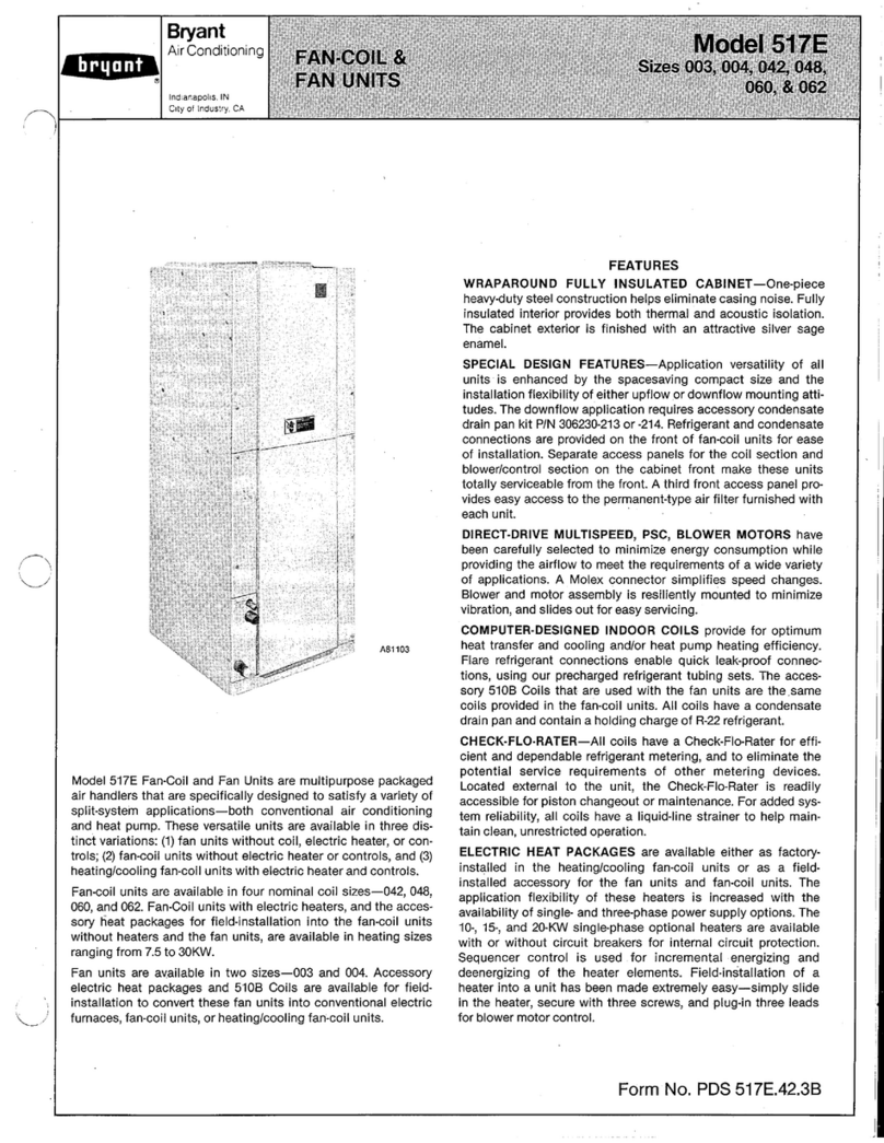
  9. Bryant 542F User manual

Bryant 542F User manual

IMPORTANT — READ BEFORE INSTALLING
1. Read and become familiar with installation instruc-
tions before installing accessory economizer.
2. Be sure installation conforms to all local and national
codes.
SAFETY CONSIDERATIONS
Recognize safety information. This is the safety-alert symbol
( ). When you see this symbol on the unit and in instruc-
tions or manuals, be alert to the potential for personal
injury.
Understand the signal words — DANGER, WARNING and
CAUTION. These words are used with the safety-alert sym-
bol. Danger identifies the most serious hazards which will
result in severe personal injury or death. Warnings, on the
other hand, could result in personal injury. Caution is used
to identify unsafe practices which would result in minor per-
sonal injury or product and property damage.
WARNING:Before performing service or mainte-
nance operations on unit, turn off main power switch
to unit. Electrical shock could cause personal injury.
INSTALLATION
WARNING:Turn off unit power! Electrical shock and
personal injury could result.
Install economizer damper assembly as follows:
1. If base unit is installed and in operation, turn off all
power to unit.
2. Remove filter access panel then remove 25% air/
economizer hood. See Fig. 2 and 11.
3. Remove and discard 25% outdoor-air damper section.
Save screws. See Fig. 3.
4. Remove and discard shorting plug located in left front
of return-air compartment and behind unit control box.
See Fig. 3.
5. Remove economizer damper assembly from shipping car-
ton. Remove economizer control box cover. See Fig. 4.
6. Slide economizer into unit opening as shown in Fig. 5.
Package Contents
ITEM # ITEM NAME ITEM # ITEM NAME
1Frame, Middle 32 Connector, Wire
2Frame, Bottom 33 Motor, Damper
3Frame, Top 34 Screw (40)
4Frame, Side 35 Screw (4)
5Frame, Side 36 Wire Tie (3)
6Frame, Middle 37 Bolt, Capscrew (4)
7Channel, End 38 Washer, Lock (4)
8Channel, Support 39 Washer, Plate (4)
9Channel, End 40 Nut (4)
10 Blade, Damper (6) 41 Control
11 Blade, Damper (2) 42 Shaft
12 Thermistor 44 Shield
14 Screw (16) 46 Seal Strip
15 Screw (2) 47 Seal Strip (4)
16 Bar 49 Channel
17 Bar 50 Seal Strip (4)
18 Rod, Linkage 52 Seal (4)
19 Bracket, Sensor 54 Switch, Temp
20 Bearing (12) 55 Plug Asy
21 Shaft (3) 56 Wire Asy
22 Shaft (6) 57 Wire Asy
23 Lever, Damper (5) 58 Wire Asy
24 Screw, Hex Head (5) 59 Wire Asy
25 Nut (5) 60 Wire Asy
26 Pin (4) 61 Wire Asy (2)
27 Cotter Pin (4)
28 Washer (3)
29 Linkage (2)
30 Bushing, Snap (2)
NOTE: If quantity of item is more than one, number of items is listed in parenthesis after the item
name. Example: Screw (16). See Fig. 1 for economizer details.
installation instructions
ACCESSORY INTEGRATED
ECONOMIZER
P/N 389041-201
542F, 559D,
579D, 599D
Cooling Sizes
150, 180 & 216
Cancels: 40579DP426-B IIK 559D-150-1
3/2/92
Fig. 1 — Economizer Details
—2—
Fig. 1 — Economizer Details (cont)
FILTER ACCESS PANEL
UNIT TOP
COVER
25% AIR/
ECONOMIZER
HOOD
OUTDOOR
AIR FANS
Fig. 2 — Base Unit Details
Fig. 3 — 25% Outdoor-Air Section Details
25% OUTDOOR
AIR DAMPER MIXED AIR
SENSOR ECONOMIZER
CONTROL WIRING
LINKAGE
DAMPER
MOTOR
ENTHALPY
CONTROL
MODULE
COOLING
LOCKOUT
SWITCH
Fig. 4 — Economizer Damper Assembly — Inside View
ECONOMIZER
DAMPER
ASSEMBLY
COOLING
LOCKOUT
SWITCH
ENTHALPY
CONTROL
ASSEMBLY
Fig. 5 — Economizer Damper Installation Details —
Partially Installed
—3—
NOTE: As damper assembly is inserted into unit, connect econo-
mizer plug to the receptacle behind the unit control box where
shorting plug was removed.
7. Install sheet-metal barrier (Fig. 6) to damper assem-
bly. With economizer damper in open position, pass bar-
rier through lower damper opening. See Fig. 7. Rotate
barrier 90 degrees and position to cover economizer plug
and wiring harness as shown in Fig. 8. Using screws
from assembly package, secure barrier to assembly.
8. Complete assembly of economizer damper assembly to
unit. See Fig. 9 for an end view of an installed econo-
mizer. Ensure that economizer bottom flange is posi-
tioned on basepan as shown.
9. Using four screws removed in step 3, secure econo-
mizer damper assembly to unit. See Fig. 10.
10. Reinstall 25% air/economizer hood. Refer to unit In-
stallation Instructions. See Fig. 11.
Fig. 6 — Sheet Metal Barrier
Fig. 7 — Barrier Installation Details
Fig. 8 — Sheet Metal Barrier Installation
Fig. 9 — Economizer Damper Assembly — End View
—4—
START-UP
NOTE: Remove filter access panel (Fig. 2) to gain access to
enthalpy control, mixed-air thermostat, and damper motor.
A. Enthalpy Control Setting
Set enthalpy control (Fig. 10-13) to the desired temperature
and relative humidity which provides cooling with outside air
only (no compressor operation).
Proceed as follows to determine the appropriate setting of the
enthalpy control.
1. Determine the maximum combination of relative hu-
midity and temperature of the supply air considered ac-
ceptable for the installation.
2. Refer to Fig. 14 and locate the percent of humidity on
the left-hand scale and the outdoor dry-bulb tempera-
ture on the right-hand scale. Example in Fig. 14 uses
60% rh (relative humidity) and 66 F outdoor air.
3. Draw a straight line connecting the two points.
4. Adjust enthalpy control dial (Fig. 11) to the control set-
ting indicated on control setting scale in Fig. 14. The
control setting for the example conditions is the B range.
B. Damper Vent Setting
1. Set thermostat FAN switch at ON (continuous fan op-
eration) and close night switch (if used).
2. Set thermostat SYSTEM switch at OFF.
3. Turn damper adjustment screw, located on the en-
thalpy control module, slowly clockwise until dampers
assume desired vent position. Do not manually operate
damper motor. Damage to damper motor will result.
4. Replace access panels before leaving unit.
Fig. 12 — Enthalpy Control Module
Fig. 13 — Enthalpy Control Module Location
SCREWS
ATTACHING
ECONOMIZER
TO UNIT (4)
Fig. 10 — Economizer Damper Assembly —
Completely Installed
Fig. 11 — Outdoor-Air Hood Details
—5—
SEQUENCE OF OPERATION
A. Cooling
Turn on power to unit. Set thermostat SYSTEM switch at
COOL and FAN switch at AUTO. Set thermostat at setting
below conditioned space temperature. The first-stage cooling
contacts will close.
If the outdoor-air enthalpy is below the enthalpy control set-
ting, the indoor blower motor starts and the outdoor-air damper
modulates to maintain the mixture of outdoor air and return
air at the mixed-air temperature setting. The outdoor-air fans
and compressors remain off.
If the outdoor air is above enthalpy control setting, the outdoor-
air damper moves to vent position. Cooling operation is as
described for base unit in unit Installation Instructions.
A freeze protection thermostat (FPT) is located on the indoor
coil. It detects ice buildup and turns off the compressor, thus
allowing the coil to clear. Once ice melts, the compressor can
be re-energized.
B. Heating
Turn on power to unit. Set thermostat SYSTEM switch at
HEAT and FAN switch to AUTO. Set thermostat at setting
above conditioned space temperature. The thermostat first-
stage heating contacts will close.
The outdoor-air damper will move to vent position. The heat-
ers and indoor blower motor will operate.
The outdoor-air damper will close, the indoor blower and the
heaters will shut off when the thermostat is satisfied.
C. Power Failure
The damper is equipped with a spring return. In the event of
power loss, the dampers will close until power is restored. Do
not manually operate damper motor. Damage to motor will
result.
MAINTENANCE
I. OUTDOOR-AIR INLET SCREENS
Loosen filter retainers and remove screens. Clean screens with
steam or hot water and detergent. Do not replace screens with
disposable filters.
II. ECONOMIZER ADJUSTMENTS
Make certain the outdoor-air damper is fully closed and the
return-air damper is fully open before completing the follow-
ing steps.
1. Turn on power to the unit.
2. Turn the thermostat fan switch to the ON position. The
damper will go to the vent position.
3. Adjust the vent position with the minimum position
adjustment on the enthalpy control module located on
the damper motor. See Fig. 12 and 13.
4. Set the system selector switch to COOL position and
set the cooling temperature selector to its lowest
setting.
NOTE: The cooling mode may also be simulated by remov-
ing the thermostat wires from terminals Y1 and Y2 and
installing a jumper between terminals R andY1. Refer to unit
label diagram for terminal locations.
5. Set the enthalpy adjustment on the enthalpy control
module to ‘‘A’’ for maximum benefit of outdoor air. (See
Fig. 12). If the outdoor temperature is below 70 F, the
economizer will control the mixed air with the mixed-
air sensor. If the outdoor air is above 70 F, spray a small
amount of refrigerant into the upper left vent of the
enthalpy sensor. (See Fig. 15.)
6. Jumper terminal T to terminal T1 on the module (see
Fig. 12). The economizer will go to the full open posi-
tion. The outdoor-air damper will go to the full open
position, and the return-air damper will go to the full
closed position.
7. Adjust mechanical linkage, if necessary, for correct
positioning. It may be necessary to remove the filters
to adjust the linkage.
8. Remove the jumper from terminals T and T1 installed
in Step 6.
9. If the cooling mode was simulated to operate the unit
in Step 4, remove the jumper and reconnect the ther-
mostat wires to terminals Y1 and Y2.
10. Cooling lockout switch has fixed setting to prevent com-
pressor from operating with integrated economizer
below 50 F outdoor-air temperature.
11. Continue to the Enthalpy Control Checkout Proce-
dures section below, and follow the appropriate direc-
tions to test the enthalpy control.
Fig. 14 — Nomograph for Determining Enthalpy
Control Setting
—6—
III. ENTHALPY CONTROL CHECKOUT PROCEDURES
A. Solid-State Enthalpy Control
Use this procedure for the solid-state enthalpy control that
comes standard with the economizer. (See table below.)
Solid-State Enthalpy Control Contents
PART NO.
HF25CA003 Economizer Motor
Economizer Logic Module
HH57AC078 Solid-Stage Enthalpy Sensor
HH79AZ001 Mixed-Air Sensor
1. Disconnect power at terminals TR and TR1. Dis-
connect jumper across terminals P and P1.
2. Jumper terminals TR and 1.
3. Connect enthalpy sensor to terminals SO and +. The
factory-installed 620-ohm resistor should be in place
on terminals SR and +.
4. Turn enthalpy set point to ‘‘A.’’
5. Jumper terminal T to terminal T1.
6. Spray a small amount of refrigerant in the upper left
vent of the enthalpy sensor to simulate low enthalpy
conditions. (See Fig. 15.)
7. Connect 24-v power at terminals TR and TR1. The LED
(light-emitting diode) will turn on and the economizer
motor will drive the damper full open.
8. Disconnect the jumper at terminals T and T1. The econo-
mizer motor will drive the damper full closed.
9. Connect a jumper across terminals P and P1.
10. Turn minimum position potentiometer adjustment coun-
terclockwise and the economizer motor drives the damper
closed.
11. Turn minimum position potentiometer adjustment clock-
wise and the economizer motor drives the damper open.
12. Disconnect the power at terminals TR and TR1. The
economizer motor spring-returns the damper to closed
position.
B. Differential Enthalpy Control
Use this checkout procedure for the accessory differential
enthalpy control. The differential enthalpy control kit con-
tains one solid-state enthalpy sensor (part no. HH57AC078)
to be installed in addition to the solid-state enthalpy control
which comes standard with the economizer. See table on
this page for standard solid-state enthalpy control package
contents.
1. Disconnect the power at terminals TR and TR1. See
Fig. 12.
2. Disconnect the jumper across terminals P and P1.
3. Disconnect the factory-installed 620-ohm resistor.
4. Connect one enthalpy sensor to terminals SO and +.
5. Connect the other enthalpy sensor to terminals SR
and +.
6. Turn the enthalpy set point past the ‘‘D’’ setting (fully
clockwise).
7. Connect a jumper across terminals T and T1.
8. Spray a small amount of refrigerant in upper left vent
of enthalpy sensor connected to SO and + to simulate
low outdoor-air enthalpy. (See Fig. 15.)
9. Reconnect power at terminals TR and TR1. The LED
(Light-emitting diode) turns on, and the economizer
motor drives the damper open.
10. Spray a small amount of refrigerant in upper left vent
of enthalpy sensor connected to SR and + to simulate
low return-air enthalpy. (See Fig. 15.) The LED turns
off, and the economizer motor drives the damper closed.
Fig. 15 — Use of Refrigerant Spray on Sensor to
Simulate Low Enthalpy
—7—
Copyright 1992 Carrier Corporation CATALOG NO. BDP-3355-909

Other manuals for 542F

1

This manual suits for next models

3

Other Bryant Fan manuals

Bryant CAPVP series User manual

Bryant

Bryant CAPVP series User manual

Bryant HRVBBLHA User manual

Bryant

Bryant HRVBBLHA User manual

Bryant ERVBBSVA1100 User manual

Bryant

Bryant ERVBBSVA1100 User manual

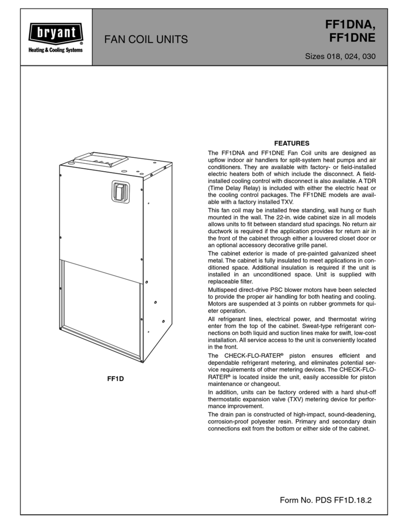
Bryant FAN COIL UNITS FF1DNA User manual

Bryant

Bryant FAN COIL UNITS FF1DNA User manual

Bryant HRVBBLHA User manual

Bryant

Bryant HRVBBLHA User manual

Bryant HRVXX Operation manual

Bryant

Bryant HRVXX Operation manual

Bryant HRVBBLHU Guide

Bryant

Bryant HRVBBLHU Guide

Bryant HRVBBLHA Operation manual

Bryant

Bryant HRVBBLHA Operation manual

Bryant HEAT RECOVERY VENTILATOR ERVBBLHA Operation manual

Bryant

Bryant HEAT RECOVERY VENTILATOR ERVBBLHA Operation manual

Bryant ERVBBLHA Operation manual

Bryant

Bryant ERVBBLHA Operation manual

Bryant ERVBBLHA Guide

Bryant

Bryant ERVBBLHA Guide

Bryant ERVBBLHA Series User manual

Bryant

Bryant ERVBBLHA Series User manual

Bryant PAYNE 619C Installation and maintenance instructions

Bryant

Bryant PAYNE 619C Installation and maintenance instructions

Bryant FA4A User manual

Bryant

Bryant FA4A User manual

Bryant FNCCAB series User manual

Bryant

Bryant FNCCAB series User manual

Bryant FX4D Operation manual

Bryant

Bryant FX4D Operation manual

Bryant 517E User manual

Bryant

Bryant 517E User manual

Bryant ERVBBSVB Operation manual

Bryant

Bryant ERVBBSVB Operation manual

Bryant FAN UNIT FH4B User manual

Bryant

Bryant FAN UNIT FH4B User manual

Bryant PERFECT AIR 1620 User manual

Bryant

Bryant PERFECT AIR 1620 User manual

Bryant 619E Series Dimensions and installation guide

Bryant

Bryant 619E Series Dimensions and installation guide

Popular Fan manuals by other brands

Hunter 51583 installation manual

Hunter

Hunter 51583 installation manual

DOSHISHA FSV-95B user manual

DOSHISHA

DOSHISHA FSV-95B user manual

Titus T3SQ-2 installation manual

Titus

Titus T3SQ-2 installation manual

EDM Product 33813 instruction manual

EDM Product

EDM Product 33813 instruction manual

Progress Lighting AirPro Schaal P250101 installation manual

Progress Lighting

Progress Lighting AirPro Schaal P250101 installation manual

Klarstein 10032447 manual

Klarstein

Klarstein 10032447 manual

Vents Quiet-S V user manual

Vents

Vents Quiet-S V user manual

BLAUBERG Ventilatoren Line user manual

BLAUBERG Ventilatoren

BLAUBERG Ventilatoren Line user manual

Lasko 5566 operating manual

Lasko

Lasko 5566 operating manual

Vents TT PRO EC user manual

Vents

Vents TT PRO EC user manual

Mars COMFORT-AIRE FP-1430DTO-MBL owner's manual

Mars

Mars COMFORT-AIRE FP-1430DTO-MBL owner's manual

Hunter 20808 installation instructions

Hunter

Hunter 20808 installation instructions

Salda KUB EKO Installation instruction

Salda

Salda KUB EKO Installation instruction

Lasko CYCLONE A20561 operating manual

Lasko

Lasko CYCLONE A20561 operating manual

Wine Guardian Through-the-Wall manual

Wine Guardian

Wine Guardian Through-the-Wall manual

NuAire SQURBO XBOX Installation and Maintenance

NuAire

NuAire SQURBO XBOX Installation and Maintenance

Master CD 5000 operating manual

Master

Master CD 5000 operating manual

Ruck Ventilatoren KVRI 5025 E2 20 Assembly instruction

Ruck Ventilatoren

Ruck Ventilatoren KVRI 5025 E2 20 Assembly instruction

manuals.online logo
manuals.online logoBrands
  • About & Mission
  • Contact us
  • Privacy Policy
  • Terms and Conditions

Copyright 2025 Manuals.Online. All Rights Reserved.