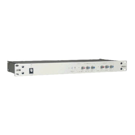
BST ekrPro Com60 User manual

ekrPro Com60 web guide controller EDV-No.: MD.191.01.05/1.6.x
with analog sensors Date: 23.11.2007
BST Web Guiding System
ekrPro Com60
with analog sensors
BST International GmbH
Heidsieker Heide 53
33739 Bielefeld, Germany
Tel: +49 5206/999-0
Fax: +49 5206/999-999

ekrPro Com60 web guide controller EDV No.:MD.191.01.05/1.6.x
with analog sensors Date: 23.11.2007
Symbols used in this operating manual
Warning signs Symbols are used in this operating manual in order to clearly
indicate particularly important places.
Attention!
You must obey this type of warning, in order to protect
yourself, as the operator, from bodily injuries arising
from mechanical movements.
Beware!
You must obey by this type of warning without fail, in
order to protect yourself, as the operator, from life
threatening injuries caused by electrical voltages.
Note
This symbol is used to point out additional useful tips,
which will help you to make optimum use of all of the
functions.
Using the keys Using the keys is represented by the following symbols in this
manual:
Press key.
Key combinations, keys have to be
pressed simultaneously.
Press keys in the specified order.
LED operating status
indications Some keys on the front panel of the ekrPro Com60 controller have
LED´s (light-emitting diodes) integrated in them. The different LED
operating states are represented as follows:
LED off
LED constantly lit = activated phase
LED flashing
!
1) 2)
+

ekrPro Com60 web guide controller EDV No.: MD.191.01.05/1.6.x
with analog sensors Date: 23.11.2007
Contents
Symbols used in this operating manual
Table of contents
Section A General information
Section B Commissioning
Section C Operation
Section D Appendix

ekrPro Com60 web guide controller EDV No.:MD.191.01.05/1.6.x
with analog sensors Date: 23.11.2007
Section A
General information
A 1 Description
A 2 Specifications
A 3 Transport / Storage
A 4 Decommissioning
ekrPro Com
60
with analog sensors

ekrPro Com60 web guide controller EDV No.:MD.191.01.05/1.6.x
with analog sensors Date: 23.11.2007 Page: 1/1
Contents
Section A
General information
Symbols used in this manual
Table of contents
A 1 Description A1-1
A 1.1 General information A1-1
A 1.2 Utilisation A1-1
A 1.3 Housing versions A1-1
A 1.4 General definitions A1-2
A 1.4.1 Assignment of sensors to the guiding mode A1-2
selection keys
A 1.4.2 Inverting of the sensor signal A1-3
A 1.4.2 Size of oscillation amplitude related to sensor
scanning area A1-3
A 1.4.2 Oscillation types and curves A1-4
A 1.4.2 Allocation of FVGs for a FVGPro 2MK A1-4
A 1.5 Connectable components A1-4
A 1.6 Safety information A1-5
A 1.7 Emissions A1-5
A 2 Specifications A2-1
A 2.1 ekrPro Com60 controller (version XT) A2-1
A 2.2 Optical edge sensor IR2001, IR2005 A2-3
A 2.3 Optical edge sensor IR2002 A2-3
A 2.4 IRS-U-2 A opto-electronic analog sensor A2-3
A 2.5 Ultrasonic edge sensor US2003, US2007, US2008 A2-4
A 2.6 Reflecting sensor TW 54 C 5 A2-4
A 2.7 Line sensor T 62 D 1 A2-5
A 2.8 Reflected light measuring light barrier R 42 D ... A2-5
A 2.9 Photoelectric fork sensor G 53 C2/5 A2-6
A 2.10 Switched power pack A2-7
A 3 Transport / Storage A3-1
A 4 Decommissioning A4-1

Description A 1
ekrPro Com60 web guide controller EDV No.: MD.191.01.05/1.6.x Chapter: A 1
with analog sensors Date: 23.11.2007 Page: 1/5
The start-up, maintenance and installation
instructions described in this operating manual
must be strictly adhered to!
A 1 Description
The aim of the operating manual is to enable you to use the
guiding system rapidly by explaining the basic settings for initial
start-up (start-up menu) and the conventional functions for
operation. In addition, the complex functions will be described
using selected examples for setting certain parameters.
A 1.1 General information This family of control systems includes:
•ekrPro Com60: Controller with keyboard
•ekrPro Key60: External control keyboard.
Devices in the controller family can be interconnected at different
levels into a system network via a CAN-Bus.
A 1.2 Utilisation The ekrPro Com60 is a microprocessor controlled web guiding
controller. Together with other BST components it may be used for:
•Web edge guiding (right or left)
•Web center guiding
•Guiding on continuous or interrupted printed lines
•Guiding on continuous or interrupted printed edges (still
being prepared)
•Web width measuring
The controller includes a separate control unit that can directly
control the sensor adjustment unit and it can be interconnected into
the system.
Any other utilisation must first be authorised by the manufacturer.
There are also standard PLC compatible inputs and outputs as well
as an OK-reporting system present.
A 1.3 Housing Versions The control unit ekrPro Com60 is available in two different housing
versions:
•ekrPro Com60 XT: Mounting unit
(e.g. for wall mounting)
•ekrPro Key60 Desk XT:Built-in unit
(e.g. for insertion in a
control console)
!

Description A 1
ekrPro Com60 web guide controller EDV No.: MD.191.01.05/1.6.x Chapter: A 1
with analog sensors Date: 23.11.2007 Page: 2/5
A 1.4 General
Settings
A 1.4.1 Assignment of sensors to the
to the scanning mode selection keys
In this operating manual, the edge sensors that are connected to
the controller are designated with “sensor 1” and “sensor 2”. On
the operating keyboard of the controller, the guiding mode
selection keys have the lettering „SENSOR LEFT“ and „SENSOR
RIGHT“ respectively.
According to the BST definition, the following link applies:
SENSOR LEFT = Sensor 1
SENSOR RIGHT = Sensor 2
The following is valid in respect of the sensor mounting positions:
The sensor, which is located to the left of the material in the
web movement direction (when looking from the material top
side), is sensor 1.
The material top side is the side of the material web which is not in
direct contact with the deflection pulleys of the pivoting frame.
Example 1: Example 2: Example 3:
As standard, sensor 1 (Sensor left) must be connected to
connector X50 (terminal X1), while sensor 2 (Sensor right) must be
connected to connector X51 (terminal X2) of the terminal board.
Sensor left
(Sensor 1)
Sensor right
(Sensor 2)
Sensor right
(Sensor 2)
Sensor left
(Sensor 1)
Sensor left
(Sensor 1)
Sensor right
(Sensor 2)

Description A 1
ekrPro Com60 web guide controller EDV No.: MD.191.01.05/1.6.x Chapter: A 1
with analog sensors Date: 23.11.2007 Page: 3/5
A 1.4.2 Inverting of the
sensor signal If a BST edge sensor, of typical C-design, is mounted according to
the BST definition (see section A 1.4.1) as "Sensor left" (sensor 1),
then no inversion of the sensor signal is necessary.
If a BST edge sensor is mounted according to the BST definition
as "Sensor right" (sensor 2), then inversion should be activated via
the setup menu (see section B 3.4.4.3.1).
When the control units is delivered, inversion of the
sensor signal for sensor 2 is activated (factory setting).
A 1.4.3 Size of oscillation amplitude
related to sensor scanning area
The maximum possible oscillation amplitude is 80% of the sensor
visual range.
As an example, the oscillating web position is shown herewith an
attitude of 40% in "Sensor oscillation" mode.
Sensor left
Not permitted:
►Sensor:
Invert!
30 % 70 %
0 % 100 % Sensor coverage
100 % of the sensor visual range
80 % of the sensor visual range =
maximum oscillation amplitude
Centre of sensor scanning area (visual range).
40 % of the sensor visual range
Oscillating web position
(Sensor looks to the left in the
direction of travel.)

Description A 1
ekrPro Com60 web guide controller EDV No.: MD.191.01.05/1.6.x Chapter: A 1
with analog sensors Date: 23.11.2007 Page: 4/5
A 1.4.4 Oscillation types and curves
An oscillation can be implemented either as a sensor oscillation or
an FVG oscillation.
In the case of the sensor oscillation, the curve described is a delta
function.
The FVG oscillation describes a curve in accordance with a sine
function.
Selections and settings are described under Point B 3.7.5.8.2.
A 1.4.5 Allocation of FVGs for a FVGPro 2MK
A 1.5 Connectable
components The general plan (annex C2) shows the components that can be
connected to the ekrPro Com60 controller.
FVG 1
FVG 2
Web travel direction
internal
limit switch
external
limit switch
<<< >>>
<<< >>>
>>> <<<
>>> <<<
Traverse the FVG using the
appropriate key in the menu window

Description A 1
ekrPro Com60 web guide controller EDV No.: MD.191.01.05/1.6.x Chapter: A 1
with analog sensors Date: 23.11.2007 Page: 5/5
A 1.6 Safety information The safety relevant information in accordance with DIN EN 294,
DIN EN 349 and the industry specific safety regulations must be
taken into consideration when installing the BST equipment in the
production machine, these include:
•There must be a safe distance between the BST equipment and
the machinery already installed on-site, such as machine
panels, building structure, etc.
•The interconnecting lines between the control equipment and the
control components or edge sensors must be laid so that nobody
can trip over them, they are not taught and they are well
anchored.
•Ensure that there is sufficient free headroom.
If the free passage is restricted, the relevant building
components causing the restrictions must be padded and a
danger warning signs must be attached to them (yellow/black).
Only trained specialist personnel are permitted to
undertake the assembly, installation and
commissioning!
Before starting work, ensure the equipment is
electrically isolated. To this end always carry out the
following measures:
1. Switch off
2. Prevent switching back on.
3. Check the equipment is isolated.
4. Earth.
5. Cover or shield any adjacent parts that are still live.
The mains power must always be switched off before
the equipment is opened.
If it becomes necessary to work on the open equipment
with voltage applied, then only Protection class IP 20 is
provided.
There is always increased danger because of the mains
voltage!
Do not use the chassis or machine frame as a climbing
aid or a stepladder.
Do not remove any of the safety devices.
Positioning movements will be undertaken by the
actuator during functional testing away from the
production machine and/or during the commissioning!
The relevant safety arrangements must implemented
during performance checks!
Monitor the overall safety concept of the production
machine during commissioning!
•Any transport safety devices that were used must be removed
prior to commissioning.
A 1.7 Emissions The A-rated equivalent continuous sound level of the equipment is
less than 70 dB(A).
!
!
!

Specifications A 2
ekrPro Com60 web guide controller EDV No.: MD.191.01.05/1.6.x Chapter: A 2
with analog sensors Date: 23.11.2007 Page: 1/7
A 2 Specifications
A 2.1 ekrPro Com60 controller (version XT)
Power supply 24V DC ± 5%
Power consumption 4W (without motor)
Input capacitance approx. 950µF
Controller inputs 2 x sensors, -9,75 V ...+9,75 V oder 0 V ...+9,75 V
12 bit selectable via software.
1 x sensor, -10,3 V to +10,3 V, 12 bit
1x EFE pot, -10,3 V to +10,3 V, 12 bit
1x pot return, -10,3 V to +10,3 V, 12 bit
1 x tacho, -9,0 V to + 9,0 V
1x blocking, input resistor 4.7 KΩ, operating points (<4 V (low)
and >8 V (high)), but can only be used against “+“ switched
sensors (pnp)
FVG inputs 1x blocking, no metallic separation
2x reference switch, no metallic separation
input resistor 4.7 KΩ,
operating points (<4 V (low) and >8 V (high)),
but can only be used against “+“ switched sensors (pnp),
supply 24V DC
Digital inputs 12x digital inputs, no metallic separation,
input resistor 4.7 KΩ,
operating points (<4 V (low) and >8 V (high)),
but can only be used against “+“ switched sensors (pnp),
supply 24V DC
Power supply outputs 2 x 24V (for CCD Pro camera)
Controller outputs Controller outputs -10.3V to -10 V, 12 bit 1x analog output
-10 V to +10 V, 2 mA
2x IR pulses
1x lamp supply 5 V, 1 A
Digital outputs 4 x digital outputs +24V, 1.0A per output, 1.5A in total
No metallic separation.
Protected against feedback (positive voltage)
Controller output stage 1x DC motor 24V DC, max. 3 A, short circuit protected.
Select voltage, current or tachometer control (in preparation)
PWM 20 kHz
FVG output stage 1 x stepping motor, max. 1.5A; not short circuit protected
CAN-bus 1x plug, 1x socket; no metallic separation
Screw connections /
plugs
Variable through exchangeable connection plate;
see Appendix D6
Protection class IP 54

Specifications A 2
ekrPro Com60 web guide controller EDV No.: MD.191.01.05/1.6.x Chapter: A 2
with analog sensors Date: 23.11.2007 Page: 2/7
Display: LCD graphics module with 128 x 64 pixel and LED
background illumination
Ambient conditions: Temperature: 0° to 45°C max.
Humidity: 5% - 90%,
no condensation
Weight: ekrPro Com60: approx. 2.1 kg
ekrPro Com60 Desk: approx. 2.3 kg
Case dimensions ekrPro Com60 (Mounting unit):
Installation ekrPro Com60 Desk (Built-in unit)
2
4
0
225
1
4
0
125
max. 10
15115
105
205
140
160
240 70

Specifications A 2
ekrPro Com60 web guide controller EDV No.: MD.191.01.05/1.6.x Chapter: A 2
with analog sensors Date: 23.11.2007 Page: 3/7
A 2.2 A2.2 Optical edge sensor
IR 2001, IR 2005
Power supplies: from the controller
Measuring range, typical: 12 mm
Visual range, typical: 15 mm
Output: analog
Protection class: IP 54
Ambient conditions: Temperature: 0 to a max. 45 °C
Humidity: 5% - 90%, no condensation
Case dimensions:
(standard version)
W = 40 mm
H = 95 mm
D = 107 mm
A 2.3 Optical edge sensor
IR 2002
Power supplies: from the controller
Measuring range, typical: 8 mm
Visual range, typical: 13 mm
Output: analog
Protection class: IP 54
Ambient conditions: Temperature: 0° to 45°C max.
Humidity: 5% - 90%, no condensation
Case dimensions:
(standard version)
W = 25 mm
H = 57 mm
D = 85.5 mm
A 2.4 IRS-U-2 A opto-electronic analog sensor
See the manufacturer’s data-sheet

Specifications A 2
ekrPro Com60 web guide controller EDV No.: MD.191.01.05/1.6.x Chapter: A 2
with analog sensors Date: 23.11.2007 Page: 4/7
A 2.5 Ultra-sonic sensor
US2003, US2007,
US2008
Power supplies: from the controller
Measuring range, typical: 15 mm (US 2008 = 4 mm)
Visual range, typical: 15 mm (US 2008 = 6 mm)
Output: analog
Protection class: IP 54
Ambient conditions: Temperature: 0 to a max. 45 °C
Humidity: 5% - 90%, no condensation
Case dimensions:
(standard version)
B= 25 mm
H = 76 mm
D = 113 mm
A 2.6 Reflection button
TW 54 C5
Power supplies: 8V – 15V; from the controller
Lamp voltage: 5V; 0.8A; from the controller for:
maximum of one sensor
Measuring range: 5.0 mm at 6 mm sensing distance
2.5 mm at 13 mm sensing distance
Output signal: Negative with black areas
Positive with white areas
Protection class: IP 65
Ambient conditions: Temperature: 0 to a max. 50 °C
Humidity: 5% - 90%, no condensation
Weight: 240 g
Case dimensions: W = 26 mm
H = 54.5 mm
D = 85.5 mm

Specifications A 2
ekrPro Com60 web guide controller EDV No.: MD.191.01.05/1.6.x Chapter: A 2
with analog sensors Date: 23.11.2007 Page: 5/7
A 2.7 Line sensor T 62 D 1
Power supplies: from the controller
Lamp voltage: 5 V; 0.8 A
Sensing distance: 15 -30 mm
Measuring range: 3 -8 mm
Line widths: 0.5 -5 mm
Output voltage: 0 to ±10V
Protection class: IP 65
Ambient conditions: Temperature: 0 to a max. 50 °C
Humidity: 5% - 90%, no condensation
Weight: 1,100 g
Case dimensions: B= 67 mm
H = 105 mm
D = 128 mm
A 2.8 Reflected light
measuring light barrier R 42 D, etc.
R 42 D 12 R 42 D 16
Power supplies: +12V, 12 mA or
±12V, 15 mA or
±15V, 20 mA
Lamp voltage: 5V, 4W; from the controller for a maximum of
one sensor
Max. distance: 1 m 2 m
Measuring range
in front of front lens:
15 mm 40 mm
Diameter of light beam
in front of front lens:
25 mm 55 mm
Diameter of light beam
at half distance
40 mm 55 mm
Output voltage:
at: UB= +12 V
UB= ±12 V
UB= ±15 V
Corresponding to change in illumination:
light dark
8.5V 2V
8.5V 0V
10.5V 0V
Protection class: IP 65
Ambient conditions: Temperature: 0° – 70°C
(temperature compensation
only up to 50°C
Weight: 1,000 g 1,200 g

Specifications A 2
ekrPro Com60 web guide controller EDV No.: MD.191.01.05/1.6.x Chapter: A 2
with analog sensors Date: 23.11.2007 Page: 6/7
A 2.9 Fork light barrier
G 53 C2/5
Power supplies: from the controller
Lamp voltage: 5V
Fork width: 29 mm
Measuring range: ± 3.5 mm
Diameter of light beam: 11 mm
Protection class: IP 65
Ambient conditions: Temperature: -20 to a max. 60 °C
Humidity: 5% - 90%, no condensation
Weight: 400 g
Case dimensions: B= 21 mm
H = 85 mm
D = 87 mm

Specifications A 2
ekrPro Com60 web guide controller EDV No.: MD.191.01.05/1.6.x Chapter: A 2
with analog sensors Date: 23.11.2007 Page: 7/7
A 2.10 Switched power pack Supply of the ekrPro Com60 including the BST components takes
place over the switched power pack.
There are two supply possibilities:
1. over a central power pack in the machine
2. over a power pack allocated to the BST part
The following details are based on a control system comprising a
control unit ekrPro Com60, analogue sensors, sensor adjustment
unit and actuator (EMS1, EMS5, EMS10, EMS16, EMS17 or
EMS20)
1. Central supply
If supply takes place centrally from the machine the following
parameters are to be fulfilled:
•Output voltage: 24 V DC ± 5%
•Output current: 4.2 A DC
•Output power: 100 W
The power pack must be able to quickly charge (~ 5 sec) the input
capacitance (approx. 950µF) of the control amplifier after switching
on without recognizing this as a short circuit and so switching off
again.
The output should be permanently resistant to short-circuiting,
overloading and idle running.
2. Separate power pack
If a separate power pack is used for the BST components, we
recommend the use of units manufactured by PULS GmbH:
Input voltage: 85 - 264 V AC or 220 – 375 V DC
Output voltage: 24 V DC ± 5%
Output current: 4.2 A DC
Output power: 100 W
BST order number: 103 837
If a number of control systems are to be supplied from a single
switched power pack, then, dependent on the total required power,
the following power packs are also available:
Input voltage Output
voltage
Output
current
Output
power
BST order
number
85 – 264 V AC
220 -700 V DC 24 V DC ± 5 % 10 A DC 240 W 118 661
85 – 264 V AC
220 -700 V DC 24 V DC ± 5 % 20 A DC 480 W 109 365
340 – 479 V AC /3Ph.
450 -700 V DC 24 V DC ± 5 % 20 A DC 480 W 116 679

Transport A 3
ekrPro Com60 web guide controller EDV No.: MD.191.01.05/1.6.x Chapter: A 3
with analog sensors Date: 23.11.2007 Page: 1/1
A 3 Transport
The equipment will be shipped in accordance with the details
stipulated in the order:
•completely assembled and interconnected to the web guide
control system
•as component parts in standard cardboard boxes with cellular
lining material
If the unit will not be incorporated immediately, it should be stored
in a dry room until installation.

Decommissioning A 4
ekrPro Com60 web guide controller EDV No.: MD.191.01.05/1.6.x Chapter: A 4
with analog sensors Date: 23.11.2007 Page: 1/1
A 4 Decommissioning
Decommissioning (scraping) the systems must be carried out in
together with the entire machine.
The necessary procedures must be prepared by the manufacturer
of the machine. You must take into consideration that the control
system is generally considered to be an electrical / electronic
device, which must be disposed of in accordance with the current
legal requirements.
You might also be able to return the system to BST International
GmbH,but the corresponding agreement must be made first.

ekrPro Com60 web guide controller EDV No.:MD.191.01.05/1.6.x
with analog sensors Date: 23.11.2007
Section B
Commissioning
B 1 Installation
B 2 Controls
B 3 Commissioning
B 4 Terminal assignments and service displays
ekrPro Com
60
with analog sensors
Other manuals for ekrPro Com60
1
Table of contents
Other BST Computer Hardware manuals
