BT CARGO GT 15 User manual

© BT Industries AB
Valid only for serial number:
BT Products AB
S-595 81 MJÖLBY SWEDEN
Operator’s Manual GB
WARNING!
Do not use the truck before
first reading through the
OPERATOR’S MANUAL.
NOTE!
Keep for future reference.
CARGO GT 15, 18, 20, 25, 30
CARGO DT 15, 18, 20, 20P, 25, 25p, 30, 30P, 35
CARGO GT 35
CARGO DT 35
Valid from serial number:
Order number: 180424-040
Issued: 2000-10-18 ITS

© BT Industries AB 180424-040
2
Note to Operators and Supervisors
This manual explains the proper operation and maintenance of
BT industrial vehicles as well as daily lubrication and periodic
inspection procedures.
Please read this manual thoroughly even though you may
already be familiar with other BT industrial vehicles because it
contains information which is exclusive to this series of vehicles.
The manual has been produced based on a standard vehicle.
However, if you have questions on other types, please contact
your BT industrial vehicle dealer (BT dealer).
In addition to this manual, it is essential that you review the sep-
arate publication entitled “Operator’s Manual for Safety Opera-
tion” for forklift truck drivers. It contains important information
about the safe operation of forklift trucks. BT reserves the right
to make any changes or modifications of specifications in this
manual without giving previous notice and without incurring any
obligation.

© BT Industries AB 180424-040
3
Table of Contents
Before Initial Operation ...................................................................... 7
Precautions to be taken when using SAS Models 8
Description of features available in SAS models 9
Automatic fork leveling control 9
Active mast front tilt angle control 11
Active mast rear tilt speed control 12
Key-lift interlock 12
Active steering synchronizer 12
Action to be taken in emergency 13
Main Components ............................................................................. 14
Driving Controls and Instrument Panel .......................................... 15
Torque converter Models 15
Instruments ....................................................................................... 16
Integrated monitoring center 16
Each warning lamp check method 17
Hour meter also serving as an SAS diagnosis indicator (SAS models) 17
Engine oil pressure warning lamp 17
Sedimenter warning lamp 18
Glow indicator lamp 18
Preheating indicator lamp 18
Air cleaner warning lamp 19
Charge warning lamp 19
Water temperature gauge 19
Fuel gauge 20
Reference 20
SAS warning lamp 20
Swing lock indicator lamp 21
Speed control warning lamp 21
Torque converter oil temperature gauge 21
Switches and Levers ........................................................................ 22
Ignition switch 22
Integrated light and turn signal switch 23
Light control switch 23
Turn signal switch 23
Vehicular speed limiter 23
Control lever 24
Horn button 24
Lift lever 24
Key-lift interlock 25
Tilt lever 25
Tilt lever knob switch 25
Parking brake lever 26
Tilt steering adjustment 26

© BT Industries AB 180424-040
4
Table of Contents
Pedals 26
Body Components .......................................................................... 27
Operator’s seat 27
Suspension seat 27
Seat belt 27
Engine hood 28
Forks 29
Draw bar 29
Vehicle hoisting method 29
Handling the BT DPF-II System (Option) ........................................ 30
Display 31
Explanation of display 31
BT DPF-II System maintenance method (Option) 32
Maintenance operation procedure 32
Pre-Operation Check ...................................................................... 35
Pre-operation check 35
Walk around inspection 36
Vehicle uprightness 36
Beneath the vehicle 36
Tire inspection 36
Hub nut inspection 36
Engine compartment inspection 37
Engine coolant level check and supply 37
Checking hydraulic oil level 38
Engine oil inspection 39
Adding engine oil 39
Leakage inspection 39
On board vehicle inspection 39
Brake fluid inspection 39
Brake pedal inspection 40
Parking brake inspection 40
Inching and brake pedal 40
Instrument inspection 41
Fuel level check and supply 41
Engine inspection 41
Load handling system 42
Steering wheel inspection 42
While moving slowly 42
Clutch disengagement and slipping 42
Brake effectiveness 42
Steering inspection 42
Inspecting SAS system 43
Before Garaging the Vehicle ............................................................ 44
Weekly Maintenance ......................................................................... 45

© BT Industries AB 180424-040
5
Table of Contents
Air cleaner cleaning 45
Element cleaning 45
How to wash the element 45
Fan belt inspection 46
Battery electrolyte check 46
Torque converter oil inspection 47
Retightening of bolts and nuts 47
Greasing mast and steering linkage 47
When the battery is dead 47
Self Servicing .................................................................................... 48
Changing tires 48
Front wheels 48
Rear wheels 48
Jack setting position 49
Adding antifreeze 49
Fuse replacement 50
Fuse assignment 50
Air purge of the fuel system 51
Draining the sedimenter 51
Maintaining the battery 52
Adjustment of parking brake operating force 52
Fuel Tank Check ............................................................................ 53
Frame Serial Number ..................................................................... 53
Frame serial number location 53
How to Read the Name Plate ......................................................... 53
Lubrication Chart .............................................................................. 54
Periodic Maintenance ....................................................................... 55
Periodic Replacement Table .......................................................... 56
Protect Your Investment with BT Genuine Parts ............................ 57
Periodic Maintenance Table ........................................................... 58
Service Data ................................................................................... 64
Adjustment value table 64
Lubricant capacities and types 65
LPG Device (Option) ......................................................................... 66
Names of LPG Device Components ............................................... 66
Switches ......................................................................................... 67
Fuel Switch 67
Fuel switch (gasoline/LPG models) 67
LPG low fuel warning light (France spec: OPT) 67
LPG Tank and Related Parts ............................................................ 68
Outflow Valve 68
Inflow Valve 68

© BT Industries AB 180424-040
6
Table of Contents
Pipe Valve 68
Relief Valve (Australian market type) 68
Operating LPG-Powered Forklifts ................................................... 69
Starting the Engine (LPG Models) 69
Starting the Engine 70
To prolong the Engine Life 70
Parking 70
Changing the LPG Tank 71
ENGINE HOOD 71
Opening 71
Closing 72
Removing the tank 72
Installing the tank 73
Important Information about Properties of LPG 73
Safety Precautions about Operating LPG-Powered Forklifts 74
Servicing the Regulator .................................................................. 75
Removing Tar from the Regulator 75
Inspecting and Servicing LPG-Powered Forklifts ........................... 75
Lubricant and Coolant .................................................................... 77
Engine oil 77
Cooling water 77
Engine Specifications ..................................................................... 77
Mast Specifications and Rated Capacities ..................................... 78
GT 15, DT 15 79
GT 18, DT 18 80
GT 20, DT 20P, DT 20 81
GT 25, DT 25P, DT 25 82
GT 30, DT 30P, DT 30 83
GT 35, DT 35 84
Wheel and Tire .................................................................................. 85
Vehicle Dimensions .......................................................................... 87
Recommended Lubricants ............................................................... 89

Before Initial Operation
© BT Industries AB 180424-040
7
Before Initial Operation
•Please read this manual thoroughly. This will give you a
complete understanding of BT industrial vehicles and permit
you to operate them correctly and safely.
Proper handling of new vehicles promotes performance and
extends service life. Drive with special caution while becom-
ing familiar with a new vehicle.
In addition to the standard operating procedures, pay atten-
tion to the following safety items.
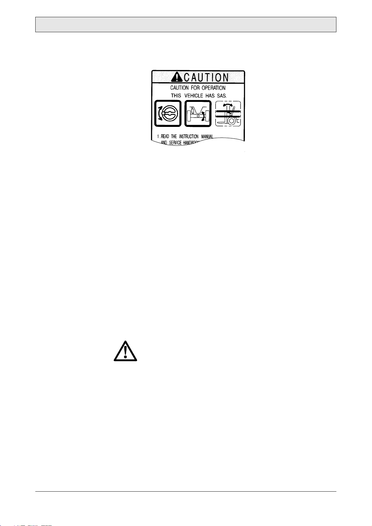
•Please acquire thorough knowledge on BT industrial
vehicle. Read the operator’s manual thoroughly prior to oper-
ating the vehicle. Get to know its operation and components.
Learn about the safety devices and accessory equipment and
their limits and precautions. Be sure to read the caution plate
attached to the vehicle.
•Please learn safe driving points and safety management.
Understand and maintain working area traffic rules. Ask the
work area supervisor about any special working precautions.
•Wear neat clothing for operation. Improper clothing for
vehicle operation may interfere smooth operation and cause
an unexpected accident. Always wear proper clothing for
easy operation.
•Please keep away from live electric power lines. Know the
locations of inside and outside power lines and maintain suffi-
cient distance.
•Be sure to perform pre-operation check and periodic
maintenance. This will prevent sudden malfunctions,
improve work efficiency, save money and insure safe working
conditions.
• Always warm up the engine before starting operation.
•Be sure to avoid forward tilt when the loaded fork is
raised. In the worst case, this will cause overturning due to
poor stability resulting from forward shifting of the center of
gravity.
•Never attempt traveling with a loaded on the lifted fork
beyond the specified height. Traveling with a load on the
fork lifted beyond the specified height may cause overturning
due to upward shifting of the center of gravity. Keep the fork
at 10-20cm (5.9-7.9in)above the ground when traveling.
•Please avoid overloading or uneven loading. Overloading
or uneven loading is dangerous. If the center of gravity is
nearer to the front side even though the load is below the
maximum, limit the loading weight according to the load table.
• If you hear and unusual noise or sense anything unusual,
inspect and repair immediately.

Before Initial Operation
© BT Industries AB 180424-040
8
• Be sure to observe the correct operating procedures and
precautions for the handling of vehicles equipped with
power steering and power brakes.
•If the engine stops during traveling, the operation will be
affected. Stop the vehicle in a safe place as described below.
Steering operation becomes heavy because the power device
for the power steering becomes ineffective. Operate the
steering wheel more firmly than usual.
•Please use only the recommended types of fuel and
lubricants. Low-grade fuel andlubricants will shorten service
life.
• Flammable and/or combustible materials can be dam-
aged, and in some cases ignited, by a hot exhaust sys-
tem or hot exhaust gases.
To minimize the possibility for such damage or fire, the
operator must obey the following recommended prac-
tices:
• Do not operate lift truck over or near flammable and/or com-
bustible materials, including dried grass and paper scraps.
• Park lift truck with rear end at least 12" away from lumber,
veneer board, paper products and other similar materials to
avoid discoloration, deformation or combustion of those
materials.
Precautions to be taken when using SAS Models
(SAS: System of Active Stability)
CAUTION!
• Whenever you may get on an SAS model, please check the
caution plate, through which you may know what functional
features are provided in the vehicle. Do not proceed to an
operation of the vehicle before making certain that each of the
features is operating properly.

Before Initial Operation
© BT Industries AB 180424-040
9
• Example: These symbols indicate that the vehicle is not pro-
vided with such controls as active mast front tilt angle control.
• While driving the vehicle, be normally alert about a warning
lamp and/or an alarm buzzer. Should an error code be indi-
cated by a warning lamp or hour-meter, park the vehicle at a
safe location and ask a BT dealer for an inspection.
• The SAS, which is electronically controlled, need be initial-
ized after completion of a maintenance operation. Do not
unnecessarily remove or modify any SAS features. Whenever
an inspection may be necessary, make contact with a BT
dealer.
• When washing the vehicle, carefully prevent water from
splashing directly over the electronics (controller, sensor and
switches) employed in the SAS.
Description of features available in SAS models
Active control rear stabilizer:
When the vehicle makes a turn on the spot, a centrifugal force
will be generated in the lateral direction of the vehicle. In such
event, this feature will operate so that rear wheels will be locked
from swinging to support the vehicle on four wheels. Thus, the
vehicular stability will be enhanced in both right and left direc-
tions.
CAUTION!
With the vehicle locked from swinging, the stability does
surely increase. Nevertheless, it does not signify that the vehi-
cle would never tipover.
Operate the vehicle always correctly.
Automatic fork leveling control
• With the vehicle not loaded, tilt the mast forward while press-
ing the tilt lever knob switch. This will cause the fork to auto-
matically stop at its horizontal position (with the mast
vertically positioned).
• After stopping the fork at its horizontal position with the tilt
lever knob switch pressed, you may want to tilt the fork fur-
ther. To do this, return the tilt lever to the neutral position
once. Then, after releasing the tilt lever knob switch, operate
the tilt lever.

Before Initial Operation
© BT Industries AB 180424-040
10
When the tilt lever is operated from the backward to forward
position with the knob switch depressed, the mast will perform
as follows:
CAUTION!
• With the mast tilted forward with a high load at a high lift,
pressing the tilt lever knob switch will cause the mast to stop
moving. Absolutely avoid such operation because this auto-
matic fork leveling control, if operated while handling a load,
involves the fear of causing the vehicle to tipover.
• In case of the vehicle with an attachment, do not allow the
fork to be automatically positioned horizontally, with a high
load at a high lift while the engine is running at a high speed.
This will lead to a hazard.
• Some specialty models onto which a heavy attachment is
mounted may not be equipped with the automatic fork leveling
control. Confirm a BT dealer in advance.
Note:
• The mast will not move if it is tilted forward by pressing the tilt
lever knob switch with a high load at a high lift (more than 2
m).
• As long as the mast is tilted forward from its vertical position,
it will no longer tilt forward even if the tilt lever knob switch is
pressed.
• While it is tilting backward, the fork will not stop at its horizon-
tal position even if the tilt lever knob switch is pressed.
No load Loaded
High lift
height Stop with leveling forks
(mast vertical) Not tilting
forward
Low lift
height Stop with leveling forks
(mast vertical)

Before Initial Operation
© BT Industries AB 180424-040
11
Active mast front tilt angle control
According to a lift and to a load, the angle at which the mast can
be tilted forward is automatically controllable within a range of
angles illustrated below:
CAUTION!
• If a load should be moved up while tilting the fork forward at a
low lift, there is a fear that the vehicle may tipover when the
fork stops at the position having a tilt angle beyond the speci-
fied angle range. Never handle any load, therefore, while tilting
the mast, with the load moved up.
• With a high load at a high lift, never match the load (mast
angle) by controlling the mast forward tilting angle, since it
involves the fear that the vehicle may tip over.
• Even with a load positioned within the allowable angle range,
never tilt the mast beyond its vertical position, or the vehicle
may tipover, losing its stability forward and backward. Never
tilt the mast forward, with a load moved up.
• Some specialty models onto which a heavy attachment is
mounted may not be equipped with the mast forward tilt con-
trol. Confirm a BT dealer in advance.
• Once you have mounted or replaced any attachment on a fork
lift model, ask a BT dealer for an inspection.
• If you use two or more removable attachments alternately, the
heaviest one should be used to carry out matching (SAS set-
ting). Ask a BT dealer for help in advance.
Note:
With the fork positioned at the top dead end, a high pressure
(relief pressure) may remain in the lift cylinder. This high pres-
sure causes the vehicle to judge that it has a high load even
unless loaded. As a result, the mast will be hindered from tilting
forward. In this case, move the fork a little downward from the
top dead end (to release the pressure) and the mast may be
tilted forward.
Light load
(no load) Intermediate load Heavy load
High lift height No restriction for
front tilt angle Angle restricted
between 1° and for-
ward tilt angle 5°
Forward tilt angle
restricted to 1°
Low lift height No restriction for front tilt angle

Before Initial Operation
© BT Industries AB 180424-040
12
Active mast rear tilt speed control
• At a high lift, the mast has a backward tilt speed controlled
(slowed down) irrespective of a load. If the high lift is changed
over to the low lift while tilting the mast backward, the control-
led speed will last.
• At a low lift, the mast can be tilted at the full speed irrespec-
tive of a load. If the mast is tilted backward at a low lift with
the tilt knob switch pressed, the mast has a backward tilt
speed controlled (slowed down) as long as the tilt lever knob
switch is pressed.
• If the low lift is changed over to the high lift while tilting the
mast backward, the controlled speed will last as long as the
tilt lever knob switch is pressed. And the mast may be tilted
backward at the full speedso long as the tilt lever knob switch
is not pressed.
Key-lift interlock
With the engine killed (the ignition switch positioned at OFF), the
fork will not move down even if the lift lever is so operated.
Active steering synchronizer
If the steering wheel knob is not angularly matched with tires,
such an out-of-position will be automatically corrected while
turning the steering wheel. Thus, the knob is kept at a constant
position relative to tires.
If SAS feature should fail:
An SAS model is controlled with a controller, a sensor and vari-
ous actuators. If any of them is found not to be operating nor-
mally, it tells you that:
• Steering wheel knob out-of-position may not be corrected.
• Such features as automatic fork leveling control, active mast
front tilt angle control and active mast rear tilt speed control.
• Swing lock may not be unlocked.
If any of the phenomena referred to above should take place,
• SAS warning lamp will blink.
• Error code will be displayed in hour meter.
• Buzzer will sound.
Thus, the operator will be informed. In such event, move the
vehicle to a safe location and ask a BT dealer for a repair.

Before Initial Operation
© BT Industries AB 180424-040
13
Action to be taken in emergency
If the mast (load-handling unit) should fail to operate, remove the
SAS-ECU fuse inside the fuse box and you will be able to move
the vehicle by operating it similarly to a non-SAS model. Move
the vehicle to a safe location and ask a BT dealer for a repair.
If any phenomenon different from normal operations (failure to
run or the like), among others, should take place, ask a BT
dealer for an inspection.
Note:
Once a torque converter model has had its control lever abnor-
mal, it is impossible to manually operate the vehicle, which need
be towed, accordingly.

© BT Industries AB 180424-040
14
Main Components
Main Components
1. Mast
2. Chain
3. Fork
4. Tilt cylinder
5. Operator’s seat
6. Head guard
7. Lift cylinder
8. Steering wheel
9. Counter weight
10. Rear axle
11. Engine hood
12. Frame
13. Front axle

Driving Controls and Instrument Panel
© BT Industries AB 180424-040
15
Driving Controls and
Instrument Panel
Torque converter Models
1. Parking brake lever
2. Control lever
3. Steering wheel
4. Integrated monitoring center
5. Horn button
6. Turn signal and light control switch
7. Lift lever
8. Tilt lever
9. Tilt lever knob switch (SAS models)
10. Attachment lever
11. Ignition switch
12. Accelerator pedal
13. Brake pedal
14. Inching and brake pedal
15. Tilt steering adjust lever
16. Engine hood lock release lever
17. DPF display (Option)

Instruments
© BT Industries AB 180424-040
16
Instruments
Integrated monitoring center
Meter illumination lamp is provided for easy meter reading at
night. It comes on when the light control switch is set to ON.
1. Hour meter used also to diagnose the SAS
2. Engine oil pressure warning lamp
3. Sedimenter warning lamp (Diesel models)
4. Glow Indicator lamp (1DZ-II engine models)
Preheating indicator lamp
(2Z engine models: Standard in designate area)
5. Air cleaner cleaning warning lamp
6. Charge warning lamp
7. Water temperature gauge
8. Fuel gauge
9. SAS warning lamp (SAS models)
10. Swing lock indicator lamp (SAS models)
11. Vehicular speed control warning lamp (Option)

Instruments
© BT Industries AB 180424-040
17
Each warning lamp check method
• Please check if all warning lamps come on when the ignition
switch is turned to ON.
• If any lamp does not come on, the lamp may be burnt out.
Inspect the lamp.
Note:
Use the light control switch to check the meter-lighting lamp.
CAUTION!
• The glow indicator lamp (1DZ-II engine models) in on for 2
seconds when the engine coolant temperature exceeds 50°C.
• The preheating indicator lamp (2Z engine models) does not
come on when the engine coolant temperature exceeds 2.5°C.
Hour meter also serving as an SAS diagnosis indicator
(SAS models)
Only operates when the ignition switch is on.
It indicates the total number of vehicle operating hours.
The unit of the right most digit is 1/10 hour.
Please use this meter to grasp the timing for periodic mainte-
nance and record the operating hours.
SAS models
The hour-meter display will alternately indicate an error code
and an hour-meter reading in the SAS.
CAUTION!
Should an error code be displayed, park the vehicle at a safe
location and receive an inspection by a BT dealer.
Engine oil pressure warning lamp
Comes on to indicate low engine oil pressure while the engine is
running.
1. If normal, the lamp comes on when the ignitions switch is
turned on and goes off when the engine starts.
2. If the lamp comes on while the engine is running, either the
engine oil is insufficient or the lubrication system is faulty.
Stop the operation immediately and ask a BT dealer for
inspection and repair.
Note:
The “engine oil pressure warning lamp” does not indicate the oil
level. Check the oil level using the oil level gauge before starting
work.

Instruments
© BT Industries AB 180424-040
18
Sedimenter warning lamp
(Diesel models)
The sedimenter is a device for separating water from the fuel.
1. The warning lamp comes on to indicate water in the sedi-
menter exceeds the predetermined level while the engine is
running.
2. If normal, the lamp comes on when the ignitions switch is
turned on and goes off when the engine starts.
3. If the lamp comes on while the engine is running, drain
water immediately. (See the self service section for the
draining method.)
CAUTION!
Continued operation with the lamp on may cause seizure of the
injection pump and pump damage.
Glow indicator lamp
(1DZ-II engine models)
Indicates heating of glow plugs.
1. When the ignition switch is turned on, the lamp comes on
and glow plug heating begins.
The lamp goes off automatically when glow plug heating is
complete. The engine will start easily once the glow plugs
are heated.
Note:
The glow indicator lamp is on for 2 seconds when the engine
coolant temperature exceeds 50°C.
Preheating indicator lamp
(2Z engine models: standard in designated area)
Indicates preheating of the intake heater.
1. When the ignition switch is turned on, the lamp comes on
and preheating starts. The lamp goes off automatically when
preheating is complete. The engine will start easily.
Note:
When the engine coolant temperature exceeds 2.5°C, this lamp
does not come on because preheating is not carried out.
2. The length of preheating time is automatically controlled
according to the engine coolant temperature. It gets some-
what longer when the engine coolant temperature is low or
in a cold season.
CAUTION!
If the indicator lamp does not go off if it comes on during
engine running, the preheating intake heater may be defective.
Please ask a BT dealer for inspection and repair.

Instruments
© BT Industries AB 180424-040
19
Air cleaner warning lamp
1. This lamp comes on when the air cleaner element gets
clogged during engine running.
2. If normal, the lamp comes on when the ignition switch is
turned on and goes off when the engine starts.
3. If the lamp comes on while the engine is running, stop the
engineand clean the element and dust cup. For the cleaning
method, refer to the Weekly Inspection Section.
Charge warning lamp
1. This lamp comes on to indicate an abnormality in the charg-
ing system while the engine is running.
2. If normal, the lamp comes on when the ignition switch is
turned on and goes off when the engine starts.
3. If the lamp comes on while the engine is running, stop the
operation immediately, inspect the fan belt for cuts or loos-
ening, adjust it, and restart the engine.
If lamp does not go off, the generation system may be faulty.
Please ask a BT dealer immediately for inspection and
repair.
Water temperature gauge
Indicates the temperature of the engine cooling water.
1. Operates when the ignition switch is on.
2. In normal state, the indicator is in the green zone at the
center.
3. If the indicator is in the red zone, the engine may be over-
heated. Stop the vehicle in a safe place, idle the engine for a
while, and stop the engine when the indication falls.
4. Temporary overheating may be caused by water leakage,
insufficient engine coolant level, loosened fan belt or other
abnormality in the coolant level, loosened fan belt or other
abnormality in the cooling system.
Inspect the cooling system.

Instruments
© BT Industries AB 180424-040
20
Fuel gauge
(excluding LPG models)
Indicates the fuel level in the fuel tank in the range
of - .
It takes some time for the indication to be stabilized after the fuel
is supplied and the ignition switch is turned on.
CAUTION!
• If the road is not level, attention must be paid because the
correct level may not be indicated.
• Add fuel early when the indicator approaches .
• In case of diesel in particular, be sure to refuel it before it
runs out because once it causes the engines to stop running it
becomes necessary to bleed air from the fuel supply system.
Reference
Remaining fuel at point.
SAS warning lamp
(SAS models)
When the ignition switch is turned on, this lamp should come on.
After the engine has started up, the SAS warning lamp should
go out. Then, the SAS may be deemed operating normally.
Should an SAS feature be abnormal, the buzzer will sound,
thereby informing the operator of the abnormality.
If this warning lamp falls in any of the cases referred to below,
the system may be deemed abnormal. Then, receive an inspec-
tion by a BT dealer.
• The SAS warning lamp does not come on even if the ignition
switch is turned on.
• The SAS warning lamp may blink while the vehicle is running.
CAUTION!
Do not use the vehicle with the SAS left abnormal. If so, it may
lead to a hazard. Once the warning lamp has begun to blink,
discontinue the operation in progress and park the vehicle at a
safe location. Then, ask a BT dealer for an inspection.
1.5~1.75 ton
model 2~2.5 ton
model 3 ton model J 3.5 ton
model
7 l
1.8 US gal 9 l
2.3 US gal 9 l
2.3 US gal 9 l
2.3 US gal
This manual suits for next models
14
Table of contents
Other BT Forklift manuals