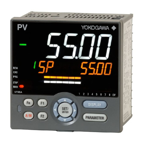
YOKOGAWA UT130 Manual

Technical
Information UT130, UT150/UT152/UT155
Temperature Controller
TI 05C01E02-01E
TI 05C01E02-01E
© Copyright Oct. 2001
1st Edition: Oct. 2001
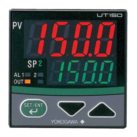
Compact Body
Large Display
48 x 48mm
Compact Body
Full Functions
48 x 48mm
Simple Operation
Less Space
48 x 96mm
Simple Operation
Large Display
96 x 96mm
Easy-to-use Controllers for Operators
Features
• Large display
• Simple operation
• Available 24V AC/DC power supply
• Dynamic AutoTune control
• Full alarm functions
• Retransmission outputs
•Timer function
• RUN / STOP switching
The following product was discontinued as of November 30, 2015.
Discontinued
p
roduct: UT152
,
UT155 Tem
p
erature Controller

Blank Page

<Toc> <Ind> <Rev> <Introduction> i
TI 05C01E02-01E 1st Edition : Oct. 31, 2001-00
INTRODUCTION
TheUT100Seriescontr ollersarethecontr ollersmainl yfortemperaturecontr ol.
TheUT100Seriescontr ollersaredevelopedusingthene westtec hnologybasedonthe
YokogawaGroup’sexperiencef orcontr olforyearsandresultscultiv atedfromman y
applications.
■Document Structure
ThisdocumentdescribesthefunctionsofUT100Seriescontrollers.
Thedocumentconsistsofthefollowingchapters.
Chapter1: Thisc hapter e xplainswhatatemperaturecontr olleris.
Chapter2: Thisc hapterexplainsthemodelandsuffixcodesofthecontr ollerandthe
informationf orordering.
Chapter3: Thisc hapter explains theP arameter Flo wchart andParameterLists ofUT
100Seriescontr ollers.
Chapter4: This c haptere xplainsthebasicoperating pr ocedureswhen usingaUT100
Seriescontr olleratfir st
Chapter5: This c haptere xplainsthe appliedoperations notdescribedinChapter4.
Chapter6: This c haptere xplainsthe basicfunctions ofUT100Seriescontr oller s.
Chapter7:Thisc haptere xplainsatr oubleshootingf orerr orsbefore/duringoperation.
Chapter8:Thisc haptere xplainstheinstallation, wiringandhar dwarespecifications.
■Intended Readers
Thisdocumentisintendedtothefollowingpersonnel:
•Instrumentationengineersorelectricalengineersplanningtouseatemperature
controller
•Instrumentationengineersorelectricalengineerswhowouldliketoknowtheoutline
ofatemperaturecontroller
■Trademark Acknowledgements
•Thecompan yandpr oductnamesref erredtointhisdocumentareeithertrademarks
orregisteredtrademarksoftheirrespectiveholders.

Blank Page

Toc-1
<Int> <Ind> <Rev>
TI 05C01E02-01E 1st Edition : Oct. 31, 2001-00
UT130, UT150/UT152/UT155
Temperature Controller
TI 05C01E02-01E 1st Edition
CONTENTS
INTRODUCTION .................................................................................................... i
1. DESCRIPTION OFTEMPERATURE CONTROL ........................................... 1-1
2. INFORMATIONTO ORDER A CONTROLLER .............................................. 2-1
2.1 Model and Suffix Codes ......................................................................................... 2-1
2.2 Mandatory Items to Specify ................................................................................... 2-5
2.3 Optional Suffix Codes to Specify........................................................................... 2-5
2.4 Other Items to Specify............................................................................................ 2-6
2.5 User’s Manual .......................................................................................................... 2-8
3. NAMES AND FUNCTIONS OF EACH PART / PARAMETER......................... 3-1
3.1 UT130 Names and Functions of Each Part (Principles of Key Operation)........... 3-1
3.2 UT130 Parameter Flowchart and Description ....................................................... 3-2
3.3
UT150/UT152/UT155Names and Functions of Each Part (Principles of Key Operation)....
3-6
3.4 UT150/UT152/UT155 Parameter Flowchart and Description ................................ 3-8
4. BASIC OPERATIONS.................................................................................... 4-1
4.1 Setting Measured InputType and Scale (Setting First)......................................... 4-1
4.2 Setting Control Action............................................................................................ 4-5
4.2.1
Selecting a Control Mode (Dynamic Auto Tune Control / PID Control / ON-OFF Control) ....
4-5
4.2.2 Switching Direct / Reverse Action ............................................................ 4-6
4.2.3 Setting CycleTime (Control Output Renewal Period) ............................... 4-8
4.3 SettingTarget Setpoint (SP) ................................................................................... 4-9
4.3.1 SettingTarget Setpoint (SP) of UT130 ..................................................... 4-9
4.3.2 SettingTarget Setpoint (SP) of UT150/UT152/UT155 ............................ 4-10
4.4 Setting Alarms ...................................................................................................... 4-12
4.4.1 Setting AlarmType and Hysteresis ........................................................ 4-12
4.4.2 Setting Alarm Setpoint........................................................................... 4-16
4.4.3 Heater Disconnection Alarm Function ................................................... 4-17

<Int> <Ind> <Rev>
TI 05C01E02-01E
Toc-2
1st Edition : Oct. 31, 2001-00
5. APPLIED OPERATIONS ............................................................................... 5-1
5.1 Changing Measured InputType and Scale ............................................................ 5-1
5.2 Correcting Measured InputValue .......................................................................... 5-1
5.3 Reducing InputVariations ...................................................................................... 5-2
5.4 Setting Maximum and MinimumValues ofTarget Setpoint Range....................... 5-2
5.5 SettingTarget Sepoint Ramp Rate (Rate-of-Change) ........................................... 5-3
5.6 UsingTwoTarget Setpoints .................................................................................... 5-4
5.7 Retransmission of Measured InputValue in Current Signal ................................ 5-4
5.8 Switching RUN/ STOP ............................................................................................ 5-5
5.9
UsingTimer Function (Turning on External Contact Outputs after the SetTime Elapses).......
5-6
5.10 Setting Key Lock................................................................................................... 5-7
5.11 Selecting Priority of PV/SP Display at Power on (for UT130 Only)..................... 5-8
5.12 Performing Heating/Cooling Control ................................................................... 5-8
5.13 Communicating with PC or PLC .......................................................................... 5-9
6. DESCRIPTION OF EACH FUNCTION ........................................................... 6-1
6.1 ON/OFF Control ...................................................................................................... 6-1
6.1.1 ON/OFF Control and Hysteresis .............................................................. 6-1
6.1.2 ON/OFF Control Application Example ..................................................... 6-1
6.2 Proportional (P) Action........................................................................................... 6-2
6.2.1 Differences between ON/OFF Action and Proportional Action ................. 6-2
6.2.2 Proportional Band (P) Details .................................................................. 6-2
6.2.3 Tuning the Proportional Band................................................................... 6-3
6.3 Integral (I) Action .................................................................................................... 6-4
6.3.1 IntegralTime (I) ....................................................................................... 6-4
6.3.2 Tuning the IntegralTime........................................................................... 6-4
6.4 Derivative (D) Action............................................................................................... 6-5
6.4.1 DerivativeTime (D).................................................................................. 6-5
6.4.2 Tuning the DerivativeTime....................................................................... 6-5
6.5 Dynamic AutoTune Control and PID Control ........................................................ 6-6
6.5.1 Dynamic AutoTune Control ..................................................................... 6-6
6.5.2 ManuallyTuning PID Constants ............................................................... 6-7
6.5.3 PID Auto-Tuning ...................................................................................... 6-7
6.6 Control Output ........................................................................................................ 6-8
6.6.1 Time Proportional PID Output (Relay Output /Voltage Pulse Output)....... 6-8
6.6.2 CycleTime .............................................................................................. 6-8
6.6.3 Continuous PID Output (4 to 20mA DC)................................................... 6-9
6.7 Overshoot Suppressing Function“SUPER” ....................................................... 6-10
6.7.1 “SUPER”Operating Principles ............................................................... 6-10
6.7.2 Effects of “SUPER” ................................................................................ 6-10

Toc-3
<Int> <Ind> <Rev>
TI 05C01E02-01E 1st Edition : Oct. 31, 2001-00
7. TROUBLESHOOTING ................................................................................... 8-1
8. INSTALLATION AND HARDWARE SPECIFICATIONS ................................. 8-1
8.1 Installation .............................................................................................................. 8-1
8.2 Panel Cutout Dimensions and External Dimensions ........................................... 8-3
8.3 Wiring ...................................................................................................................... 8-7
8.4 Hardware Specifications ...................................................................................... 8-12

Blank Page

<Toc> <Ind> 1-1
TI 05C01E02-01E 1st Edition : Oct. 31, 2001-00
1.
DESCRIPTION OFTEMPERATURE CONTROL
■Temperature Controller
The temperature controller is used to keep the fixed temperature of such as a furnace
(controlled object). In general, the temperature controller has temperature indicating
display and setpoint setting display, generates a control signal according to the differ-
ence between a indicating value (measured temperature value) and SP to finally make
the temperature agree with SP.
Sensors such as thermocouple (TC) or RTD can be connected for measuring a tem-
perature. And output types such as relay output or current output (4 to 20mA) are
prepared according to the operating terminal (heater, valve, and the like) that actually
controls a temperature.
Heater
Work
Controlled object
Measuring
object
•Thermocouple
• RTD
• SSR
• Power regulator
• Relay
• Voltage pulse
• Current
Control output
Measured input
Operating
device

1-2
<Toc> <Ind>
TI 05C01E02-01E 1st Edition : Oct. 31, 2001-00
■Types ofTemperature Control Action
ON/OFF action is the simplest action among the control actions. ON/OFF action of the
internal thermostat keeps the optimum temperature. But the temperature control
output fluctuates in the fixed cycle with ON/OFF action. If this temperature cycle
causes a problem, the control action that changes the output in proportion to the devia-
tion (the difference between the target setpoint and present value) can give a better
control performance. Thus the control action that moves the function part in proportion
to the deviation is referred to as a proportional action (P action). But a steady-state
deviation (offset) is inherently unavoidable with proportional action alone. Though the
manual reset can remove the offset, the same thing can be done using the control
action together with the Integral action (I action) that will integrate the deviation as long
as the deviation exists. This combination is referred to as a proportional-plus-integral
action (PI action). It is the popular control method among the process control actions.
On the other hand, the derivative action (D action) is the action that changes the output
in proportion to the rate-of-change of deviation. Since the output of derivative action
depends on not the amount of deviation but its rate-of-change, the larger the rate-of-
change is, the more intensive corrective action the controller takes to correct the pro-
cess response in advance. Setting each optimum value with the PID action consisted
of these three actions enables a stable control quickly.
■Dynamic AutoTune Control
The Dynamic AutoTune Control is the function to automatically determine the optimum
PID constants for continuing a good control when the controller is turned on or the
control conditions are unstable.This control method is gentle to the controlled object
itself because a disturbance needs not to be set forcibly like Auto tuning.
In Dynamic AutoTune Control, the controller automatically monitors the behavior and
determines the optimum PID constants when (1) at power on, (2) the output travels up
to 100% or down to 0% and remains there after changing a setpoint, (3) process begins
oscillating by disturbance and the like. The principle of Dynamic AutoTune Control can
be relied on because it is based on Geglar/Nichols’s control method.
Refer to “6.5.1 Dynamic AutoTune Control” on Page 6-6.

<Toc> <Ind> 2-1
TI 05C01E02-01E 1st Edition : Oct. 31, 2001-00
2.
INFORMATIONTO ORDER A CONTROLLER
2.1 Model and Suffix Codes
The models and suffix codes of UT130, UT150/UT152/UT155 standard types are as
follows:
Type
UT130-RN
UT130-VN
UT130-RN/AL
UT130-VN/AL
UT130-RN/AL/RS
UT130-VN/AL/RS
Relay output
Voltage pulse output
Relay output
Voltage pulse output
Relay output
Voltage pulse output
UT150-RN
UT150-VN
UT150-AN
UT150-RN/AL
UT150-VN/AL
UT150-AN/AL
UT150-RN/AL/RET
UT150-VN/AL/RET
UT150-AN/AL/RET
UT150-RN/AL/EX
UT150-VN/AL/EX
UT150-AN/AL/EX
UT150-RN/AL/RS
UT150-VN/AL/RS
UT150-AN/AL/RS
UT150-RN/AL/RET/EX
UT150-VN/AL/RET/EX
UT150-AN/AL/RET/EX
Relay output
Voltage pulse output
Current output
Relay output
Voltage pulse output
Current output
Relay output
Voltage pulse output
Current output
Relay output
Voltage pulse output
Current output
Relay output
Voltage pulse output
Current output
Relay output
Voltage pulse output
Current output
Standard Type Model
External Appearance Output
Options
UT152-RN
UT152-VN
UT152-AN
UT152-RN/AL
UT152-VN/AL
UT152-AN/AL
UT152-RN/AL/RET
UT152-VN/AL/RET
UT152-AN/AL/RET
UT152-RN/AL/EX
UT152-VN/AL/EX
UT152-AN/AL/EX
UT152-RN/AL/RS
UT152-VN/AL/RS
UT152-AN/AL/RS
UT152-RN/AL/RET/EX
UT152-VN/AL/RET/EX
UT152-AN/AL/RET/EX
Relay output
Voltage pulse output
Current output
Relay output
Voltage pulse output
Current output
Relay output
Voltage pulse output
Current output
Relay output
Voltage pulse output
Current output
Relay output
Voltage pulse output
Current output
Relay output
Voltage pulse output
Current output
UT155-RN
UT155-VN
UT155-AN
UT155-RN/AL
UT155-VN/AL
UT155-AN/AL
UT155-RN/AL/RET
UT155-VN/AL/RET
UT155-AN/AL/RET
UT155-RN/AL/EX
UT155-VN/AL/EX
UT155-AN/AL/EX
UT155-RN/AL/RS
UT155-VN/AL/RS
UT155-AN/AL/RS
UT155-RN/AL/RET/EX
UT155-VN/AL/RET/EX
UT155-AN/AL/RET/EX
Relay output
Voltage pulse output
Current output
Relay output
Voltage pulse output
Current output
Relay output
Voltage pulse output
Current output
Relay output
Voltage pulse output
Current output
Relay output
Voltage pulse output
Current output
Relay output
Voltage pulse output
Current output
UT130
48x48x100mm
3-digit display
Number of SP: 2
UT150
48x48x100mm
4-digit display
Number of SP: 2
UT152
48x96x100mm
4-digit display
Number of SP: 2
UT155
96x96x100mm
4-digit display
Number of SP: 2
Without alarm
Without alarm
Without alarm
With 2 alarms
Without
other options
Without
other options
Without
other options
Without
other options
With 2 alarms
With 2 alarms
Without alarm
With 2 alarms
With communication
With
retransmission
output
With external
contact input
With communication
With retransmission
output/external
contact input
With
retransmission
output
With external
contact input
With communication
With retransmission
output/external
contact input
With
retransmission
output
With external
contact input
With communication
With retransmission
output/external
contact input
Note 1: Heating/cooling control type is available in addition to the standard type described above. Refer to the following pages.
Note 2: For options, the combinations other than those mentioned above are available. Refer to the following pages.

2-2
<Toc> <Ind>
TI 05C01E02-01E 1st Edition : Oct. 31, 2001-00
■ Standard type
● UT130 StandardType:Model and Suffix Codes
Model
Model and Suffix Codes
Suffix codes Description
UT130 Temperature controller (48 x 48 x 100mm)
Control
output Relay output (time-proportional PID or on/off control)
Voltage pulse output (time-proportional PID control)
Fixed NFixed
Options
/AL
/HBA
/RS
/V24
Alarm outputs (2 points) (Note1)
Heater disconnection alarm (includes the function of " /AL" option) (Note 1)
Communication function (Note 2)
Power Supply 24V DC / 24V AC
Note 1: The "/AL" and "/HBA" options cannot be specified at the same time. The "/HBA" option includes the function
of "/AL" option.
Note 2: When specifying the "/RS" option, be sure to order the required number of copies of the Communication
Functions User’s Manual (IM05C01E12-10E) separately. (See Page 2-8.)
-R
-V
Check the package contents against the list below.
•Temperature controller (of ordered model)
......
1
•Mounting bracket
...............................
1
•User’s Manual (IM 05C01E02-01E)
.............
1
● UT150 StandardType: Model and Suffix Codes
Model
Model and Suffix Codes
Suffix Codes Description
UT150 Temperature controller (48 x 48 x 100 mm)
Control
output
-R
-V
-A
Relay output (time-proportional PID or on/off control)
Voltage pulse output (time-proportional PID control)
4 to 20mA output ( current PID) (Note1)
Fixed NFixed
Option
/AL
/HBA
/EX
/RET
/RS
/V24
Alarm outputs (2 points) (Note2)
Heater disconnection alarm (includes the function of " /AL" option)
(Notes 2 and 3)
SP1/SP2 switching, starting of timer, and RUN/STOP switching byexternal contacts
(Notes 4 and 5)
PV retransmission output in 4 to 20mA (Note 3)
Communication function (Notes 4 and 6)
Power Supply 24V DC / 24VAC
Note 1: The " /HBA" option cannot be specified when selecting "4 to 20mAoutput" as a control output type.
Note 2: The "/AL" and "/HBA" options cannot be specified at the same time. The "/HBA" option includes the function
of "/AL" option.
Note 3: The "/HBA" and "/RET" options cannot be specified at the same time.
Note 4: "/EX" and "/RS" options cannot be specified at the same time.
Note 5: Two points of external contact inputs are available. Select 2 functions among SP1/SP2 switching, starting of
timer, and RUN.STOP switching.
Note 6: When specifying the "/RS" option, be sure to order the required number of copies of the Communication
Functions User s Manual (IM05C01E12-10E) separately. (See Page 2-8)
UT150 Table of Option Combination
/AL /HBA /EX /RET /RS /V24
AA
A
A
AA
A
A
AA
A
AA
A
AA
A
A
A
A
AN/A
N/AN/A
N/A
N/A
N/A
N/A
A
A
/AL
/HBA
/EX
/RET
/RS
/V24
Check the package contents against the list below.
•Temperature controller (of ordered model)
......
1
•Mounting bracket
...............................
1
•User’s Manual (IM 05C01E12-01E)
.............
1
A : Available
N/A : Not available

<Toc> <Ind> 2-3
TI 05C01E02-01E 1st Edition : Oct. 31, 2001-00
● UT152 / UT155 StandardType:Model and Suffix Codes
Model
Model and Suffix Codes
Suffix codes Description
UT155
UT152 Temperature controller ( 96 x 96 x 100mm )
Control
output
-R
-V
-A
Relay output (time-proportional PID or on/off control)
Voltage pulse output (time-proportional PID control)
4 to 20mA output ( current PID) (Note1)
Fixed NFixed
Option
/AL
/HBA
/EX
/RET
/RS
/V24
Alarm outputs (2 points) (Note2)
Heater disconnection alarm (includes the function of "/AL" option)
(Notes 2 and 3)
SP1/SP2 switching, starting of timer, and RUN/STOP switching by external contacts (Notes 4 and 5)
PV retransmission output in 4 to 20mA (Note 3)
Communication function (Notes 4 and 5)
Power Supply 24V DC / 24VAC
Note 1: The " /HBA" option cannot be specified when selecting "4 to 20mAoutput" as a control output type.
Note 2: The "/AL" and "/HBA" options cannot be specified at the same time. The "/HBA" option includes the function
of "/AL" option.
Note 3: Two points of external contact inputs are available. Select 2 functions among SP1/SP2 switching, starting of
timer, and RUN/STOP switching.
Note 4: When specifying the "/RS" option, be sure to order the required number of copies of the Communication
Functions User’s Manual (IM 05C01E12-10E) separately. (See Page 2-8)
Temperature controller ( 48 x 96 x 100mm )
•Check the package contents against the list below.
•Temperature controller (of ordered model)
......
1
•Mounting bracket
...............................
1
•User’s Manual (IM 05C01E12-01E)
.............
1
■ Heating/CoolingType
● UT130 Heating/CoolingType: Model and Suffix Codes
Model
Model and Suffix Codes
Suffix codes Description
UT130 Temperature controller (48 x 48 x 100mm)
Control
output
for heating
-R
-V
Relay output (time-proportional PID or on/off control)
Voltage pulse output (time-proportional PID control)
Control
output
for cooling
R
V
Relay output (time-proportional PID or on/off control)
Voltage pulse output (time-proportional PID control)
Option
/AL
/HBA
/RS
/V24
Alarm outputs (2 points) (Note1)
Heater disconnection alarm (includes the function of "/AL" option) (Notes 1 and 2)
Communication function (Notes 2 and 3)
Power Supply 24V DC / 24V AC
Note 1: The "/AL" and "/HBA" options cannot be specified at the same time. The "/HBA" option includes the function
of "/AL" option.
Note 2: For heating/cooling type, the "/HBA" and "/RS" options cannot be specified at the same time.
Note 3: When specifying the "/RS" option, be sure to order the required number of copies of the Communication
Functions User’s Manual (IM05C01E12-10E) separately. (See Page 2-8)
Check the package contents against the list below.
•Temperature controller (of ordered model)
......
1
•Mounting bracket
...............................
1
•User’s Manual (IM 05C01E02-01E)
.............
1

2-4
<Toc> <Ind>
TI 05C01E02-01E 1st Edition : Oct. 31, 2001-00
● UT150 Heating/CoolingType: Model and Suffix Codes
Model
Model and Suffix Codes
Suffix codes Description
UT150 Temperature controller (48 x 48 x 100mm)
Control
output
for heating
Relay output (time-proportional PID or on/off control)
Voltage pulse output (time-proportional PID control)
4 to 20mA output ( current PID) (Note1)
Control
output
for cooling
R
V
A
Relay output (time-proportional PID or on/off control)
Voltage pulse output (time-proportional PID control)
4 to 20mA output ( current PID) (Note1)
Option
/AL
/HBA
/EX
/RS
/V24
Alarm outputs (2 points) (Note2)
Heater disconnection alarm (includes the function of " /AL" option)
(Notes 2 and 3)
SP1/SP2 switching, starting of timer, and RUN/STOP switching byexternal contacts
(Notes 3 and 4)
PV retransmission output in 4 to 20mA
Power Supply 24V DC / 24VAC
Note 1: The " /HBA" option cannot be specified when selecting "4 to 20mAoutput" as a control output type.
Note 2: The "/AL" and "/HBA" options cannot be specified at the same time. The "/HBA" option includes the function
of "/AL" option.
Note 3: The "/HBA", "/EX" and "/RS" options cannot be specified at the same time.
Note 4: Two points of external contact inputs are available. Select 2 functions among SP1/SP2 switching, starting of
timer, and RUN/STOP switching.
Note 5: When specifying the "/RS" option, be sure to order the required number of copies of the Communication
Functions User’s Manual (IM05C01E12-10E) separately. (See Page2-8)
UT150 Heating/cooling Type Table of Option Combination
/AL /HBA /EX /RS /V24
N/A A
A
A
AAA
AAA
A
A
A
N/A
N/A
N/A
N/A
N/A
N/A N/A
/AL
/HBA
/EX
/RS
/V24
-R
-V
-A
Check the package contents against the list below.
•Temperature controller (of ordered model)
......
1
•Mounting bracket
...............................
1
•User’s Manual (IM 05C01E12-01E)
.............
1
A : Available
N/A : Not available
● UT152 / UT155 Heating/CoolingType: Model and Suffix Codes
Model
Model and Suffix Codes
Suffix codes Description
UT155 Temperature controller ( 96 x 96 x 100mm )
UT152 Temperature controller ( 48 x 96 x 100mm )
Control
output
for heating
Relay output (time-proportional PID or on/off control)
Voltage pulse output (time-proportional PID control)
4 to 20mA output ( current PID) (Note1)
Control
output
for cooling
R
V
A
Relay output (time-proportional PID or on/off control)
Voltage pulse output (time-proportional PID control)
4 to 20mA output ( current PID) (Note1)
Option
/AL
/HBA
/EX
/RS
/V24
Alarm outputs (2 points) (Note2)
Heater disconnection alarm (includes the function of "/AL" option) (Note 2)
SP1/SP2 switching, starting of timer, and RUN/STOP switching by external contacts (Note 3)
Communication function (Note 4)
Power Supply 24V DC / 24V AC
Note 1: The " /HBA" option cannot be specified when selecting "4 to 20mAoutput" as control output type.
Note 2: The "/AL" and "/HBA" options cannot be specified at the same time. The "/HBA" option includes the function
of "/AL" option.
Note 3: Two points of external contact inputs are available. Select 2 functions among SP1/SP2 switching, starting of
timer, and RUN/STOP switching.
Note 4: When specifying the "/RS" option, be sure to order the required number of copies of the Communication
Functions User’s Manual (IM05C01E12-10E) separately. (See Page 2-8)
-R
-V
-A
Check the package contents against the list below.
•Temperature controller (of ordered model)
......
1
•Mounting bracket
...............................
1
•User’s Manual (IM 05C01E12-01E)
.............
1

<Toc> <Ind> 2-5
TI 05C01E02-01E 1st Edition : Oct. 31, 2001-00
2.2 Mandatory Items to Specify
Specify the following necessary items on ordering
● Specify the power supply voltage
When using 100 to 240V AC, no need to specify the item.
When using 24V AC/DC, specify the“/V24” option.
The frequency for both of them is 50/60Hz.
● Specify the control output
<Example 1>
Specify “ UT150-RN” for UT150 standard type with relay output.
<Example 2>
Specify “UT150-RV” for UT150 heating/cooling type with heating-side relay output and
cooling-side voltage pulse output.
2.3 Optional Suffix Codes to Specify
The following options are available. But some of them are not available according to
the model. See“2.1 Model and Suffix Codes”for combinations of options.
● When using one or two Alarms,specify the“ /AL“ option.
<Example> Model and Suffix Codes:UT130-RN/AL
● When using Heater Disconnection Alarm, specify the“/HBA”option. The
“/HBA” option includes the function of “/AL” option.
<Example> Model and Suffix Codes:UT150-RN/HBA
● When using Retransmission Output, specify the “ /RET” option.
<Example> Model and Suffix Codes:UT150-AN/RET
● When using twoTarget Setpoints, specify the“ /EX” option.
<Example> Model/Suffix Codes:UT150-RN/EX
● When usingTimer Function, specify the“ /AL /EX”or“/HBA /EX”options.
<Example> Model/Suffix Codes:UT150-VN/AL/EX
● When using RUN/STOP Switching Function, specify the“/EX”option.
<Example> Model/Suffix Codes:UT150-RN/EX
● When using Communication Function, specify the “ /RS” option.
<Example> Model/Suffix Codes:UT150-RN/RS

2-6
<Toc> <Ind>
TI 05C01E02-01E 1st Edition : Oct. 31, 2001-00
2.4 Other Items to Specify
■ Quality Inspection Certificate (QIC) andTraceability
The Quality Inspection Certificate (QIC) of the product at shipping is prepared.
And theTraceability, which certificates that the measuring instruments and generator
used for the product inspection conforms to the inspection of national standards, is also
prepared.
● Quality Inspection Certificate(QIC)
Model:DOCTC
● Calibration certificate (traceability)
“Traceability declaration to the national standards” and “Explanation of theYokogawa’s
internal system for traceability”
Model: Q62188-B
■ Auxiliary Equipment and Spare Parts
● 250ΩResistor
When a measured input signal is 4 to 20mA DC, the temperature controllers (UT150/
UT152/UT155) receive it after converting to a 1 to 5V DC signal.
Model Description
X010-250-2 Resistor with M3.5 crimp-on terminal lugs
12
13
Note: Connecting a
250‰
resistor to the terminals is optional.
Model: X010-250-2(resistor with M3.5 crimp-on terminal lugs)
*When receiving 4-20mA DC current signals,
set the PV input type to 1-5V DC (range code "22")
Receiving 4-20mA DC Current
Signals with UT152/UT155
4-20mA
7
8
Note: Connecting a
250‰
resistor to the terminals is optional.
Model: X010-250-2(resistor with M3.5 crimp-on terminal lugs)
*
When receiving 4-20mA DC current signals,
set the PV input type to 1-5V DC (range code "22")
Receiving 4-20mA DC Current
Signals with UT150
4-20mA
250Ω
+
—
+
—
250Ω
● Heater Disconnection Sensor (for 1 to 80A)
The heater current sensor used here is the “CTL-6-S-H” or “CTL-12-S36-8” sensor of
U.R.D., Ltd.
This sensor is to be purchased by the users themselves.
Model: CTL-6-S-H or CTL-12-S36-8

<Toc> <Ind> 2-7
TI 05C01E02-01E 1st Edition : Oct. 31, 2001-00
● Terminal Cover
Model Description
L4000FB Terminal cover for models UT130 and UT150 (1 set)
T9115YE Terminal cover for model UT152 (1 piece)
T9115YD Terminal cover for model UT155 (1 piece)
● Mounting Bracket
Model Description
L4000FA Mounting bracket for models UT130 and UT150 (1 piece)
T9115NK Mounting bracket for model UT152 (1 set)
T9115NL Mounting bracket for model UT155 (1 set)
■ Measured InputType, Scaling and Direct/Reverse Action can be Speci-
fied on Ordering
Measured input type, displayed scale at voltage input, and direct/reverse action for the
temperature controller can be specified on ordering.
Items to specify Description
Measured
input type
Specify "1" to "7", "12", "13", and "15 to "19" for UT130.
Specify "1" to "23" for UT150/UT152/UT155.
If no input type is specified at the time of ordering, the temperaturecontroller
is shipped with the parameter set to OFF (unidentified).
In this case, set the input type on customer side.
See "4.1 Setting Measured Input Type and Scale (Setting First)" for details.
Scaling
(at voltage input)
Direct/reverse
action
The displayed scale can be specified when specifying "20" to "23"
for UT150/UT152/UT155. If no scaling is specified, the temperature controller
is shipped with the parameter set to "0.1 to 100.0".
Specify "1" for direct action. If no action is specified, the temperature
controller is shipped with the parameter set to "0" (reverse action).

2-8
<Toc> <Ind>
TI 05C01E02-01E 1st Edition : Oct. 31, 2001-00
2.5 User’s Manual
User’s Manuals in A-2 size and A-4 size are prepared.
User’s Manuals supplied along with the product is in A-2 size.Both Manuals in A-4 size
and A-2 size have the same contents except for their appearances.
When specifying the ”/RS”option, be sure to order the required number of copies of
Communication Functions User’s Manual separately.
The following User’s Manuals can be purchased separately.
● User’s Manual for UT130 (A4 size)
Document Number: IM05C01E02-41E
● User’s Manual for UT150/UT152/UT155 (A4 size)
Document Number: IM05C01E12-41E
● Communication Functions User’s Manual for UT130,UT150/UT152/UT155
(A4 size)
Document Number:IM05C01E12-10E
A4-size Manual

<Toc> <Ind> 3-1
TI 05C01E02-01E 1st Edition : Oct. 31, 2001-00
3. NAMES AND FUNCTIONS OF EACH PART
/ PARAMETER
3.1 UT130 Names and Functions of Each Part
(Principles of Key Operation)
Data display (red)
•In the operating display, either PV (measured value) or
SP (target setpoint) is indicated.
Which parameter takes precedence over the other
depends on the parameter "DSP" value.
•In the parameter setting display, either the parameter
codes or parameter value is indicated.
•If an error occurs, the error code is displayed.
Alarm 1 (AL1) / Alarm 2 (AL2) lamps (red)
AL1: Lit when the alarm 1 is activated.
AL2: Lit when the alarm 2 is activated.
SP display lamp (orange)
•Lit when SP is displayed or being changed.
•Flashes slowly (approx. once every second) when
a parameter code is displayed.
•Flashes fast when a parameter value is being changed.
Output (OUT) display lamps
(Left: orange; right: green)
Lit while control output is being output.
Flashes according to the control output value during time-
proportional output.
(Flashes slowly when control output
value is small; flashes fast when control output value is large.)
•The left lamp lights up in orange during control output of
standard type.
•In heating/cooling control, the left lamp lights up in orange
when the heating-side output is active; while the right lamp
lights up in green when the cooling-side output is active.
•In the operating display, it switches between the PV (measured value)
and SP (target setpoint) displays.
•Registers the data value changed using the data change keys.
•Switches between operating displays or parameter setting display
sequentially.
•Pressing the key for 3 seconds or more in the operating display
retrieves the operating parameter setting display. You can transfer to
the setup parameter setting display form the operating parameter
setting display.
•Pressing the key for 3 seconds or more in either an operating or setup
parameter setting display transfers back to the operating display.
SET /ENT key (data registering key) Data change keys
•When PV is displayed in the operating display, a press of
the or key switches to the SP display.
•When a parameter code is displayed, pressing either key
once displays the parameter value (which can then be
changed).
•Changes SP and the parameter values.
•Pressing the key decreases the data value and
pressing the key increases it. Holding down the key
will gradually increase the speed of the change.

3-2
<Toc> <Ind>
TI 05C01E02-01E 1st Edition : Oct. 31, 2001-00
3.2 UT130 Parameter Flowchart and Description
HYS
A1
A2
HC
FL
BS
LOC
AT
P
I
D
MR
COL
Power ON
is displayed
?
YesNo
CTL=SLF
When LOC=-1,
transfers to the
setup parameter
setting display
CTL
Operating parameter setiing dispaly
Operating Display
CTL=PID
Displayed when I = OFF
Displayed for heating/
cooling type
DB
Displayed for heating/cooling type
CT
) Displayed for time-proportional PID control
CTC
Displayed for time-proportional PID control
of heating/cooling type
CTL=ONF
(on/off control)
Displayed only for the "/HBA" option and when AL1 = 25
LOC=
When LOC=
-
1
Note: If no key is pressed for a period of 2 minutes or more
while in the operating or setup parameter setting display,
the controller automatically returns to operating display.
CTL=SLF is not
permitted for heating/
cooling type.
Displays PV Displays SP
To switch between PV and SP,
press the key.
SP display lamp
is on.
Note
The data (PV or SP) selected in "DSP" is
displayed at first. (Default: PV display)
(Dynamic Auto Tune) (PIDcontrol)
To Page 3-4
SP (target setpoint) can be
changed in the operating display.
* Refert to the Measured Input Ranges on
Page 4-1.
Displayed only for the "/AL" or "/HBA" option.
Not displayed when AL1, AL2 = OFF
Not displayed when AL1, AL2 = 21 or 22
Press the key
for at least 3 seconds.
(To operating parameter
setting display)
Press the key
for at least 3 seconds.
(To operating display)
When the measured input range code has
been already set, the operating display shown
below appears.
Press the
key to move
between items.
Note
NOTE
When IN appears, press the
key to display the measured input
range code you want to use, then
press the key to register it.
After this operation, the controller
shows the operating display.
A
A
B
Set "-1" to enter the setup parameter setting
display. But if "LOC=1 or 2" is already set, the
parameter value can not be changed by setting
"LOC=-1" only. To change the parameter value,
set "LOC=0" at first (for disabling keylock),
then set "LOC=-1" once again.
NOTE
Other manuals for UT130
1
This manual suits for next models
3
Table of contents
Other YOKOGAWA Temperature Controllers manuals

YOKOGAWA
YOKOGAWA TC10 User manual

YOKOGAWA
YOKOGAWA XS550 User manual

YOKOGAWA
YOKOGAWA Green Series User manual

YOKOGAWA
YOKOGAWA UP150 User manual

YOKOGAWA
YOKOGAWA UTAdvanced UT55A User manual

YOKOGAWA
YOKOGAWA TC10 Installation and operation manual

YOKOGAWA
YOKOGAWA UT130 User manual

YOKOGAWA
YOKOGAWA UT150 User manual

YOKOGAWA
YOKOGAWA UP150 User manual

YOKOGAWA
YOKOGAWA TC User manual