Leak-Free Load-Control Valves NS 32
Qmax = 1000l/min [265 gpm],pmax = 420bar [6000 psi]
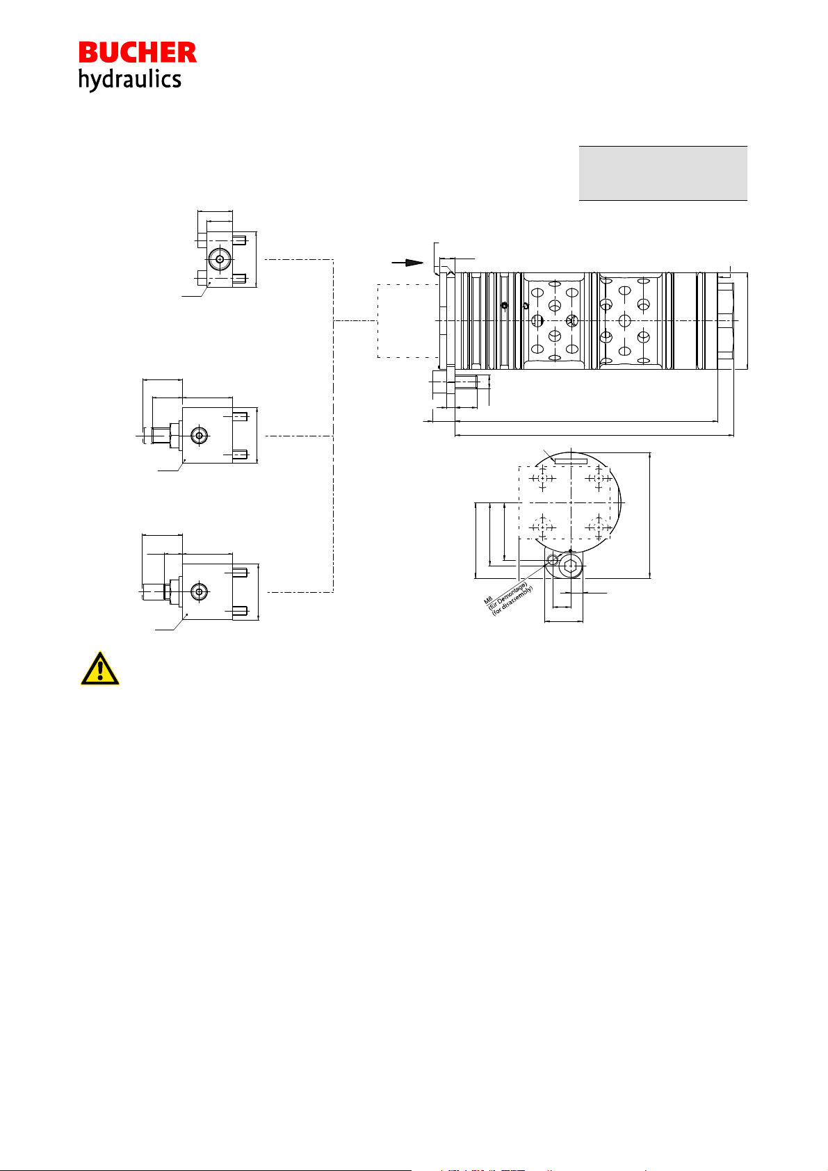
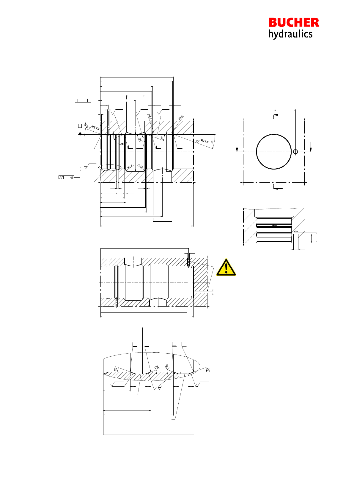
Seat-valve, two-stage hydraulic, cartridge design
Series CINDY 32-B-C...
1/9
Reference: 300-P-9050099-EN-02
Issue: 10.2016
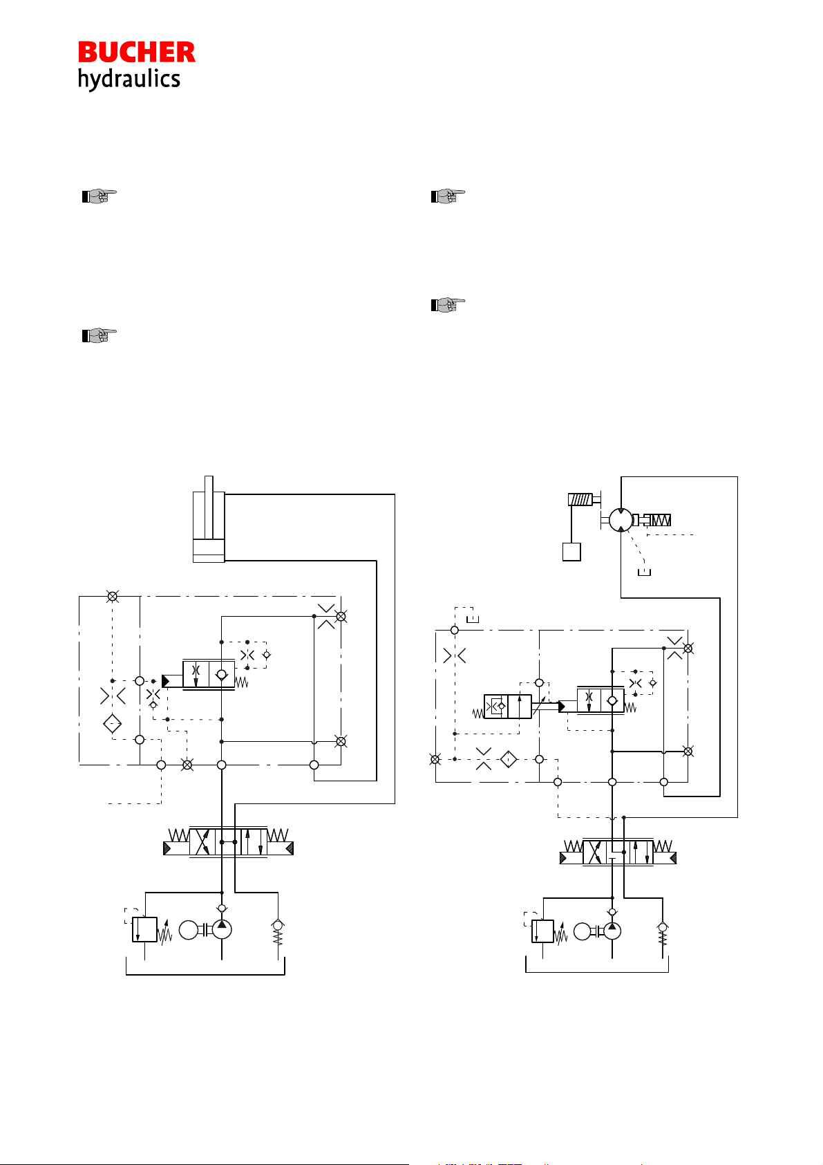
STwo-stage load-control valve and bypass check valve
are functionally combined in one coaxial valve assembly
SLeak-free load holding
SPilot ratio 1:113
SThe control assembly is guaranteed to close
→it closes even with a broken spring
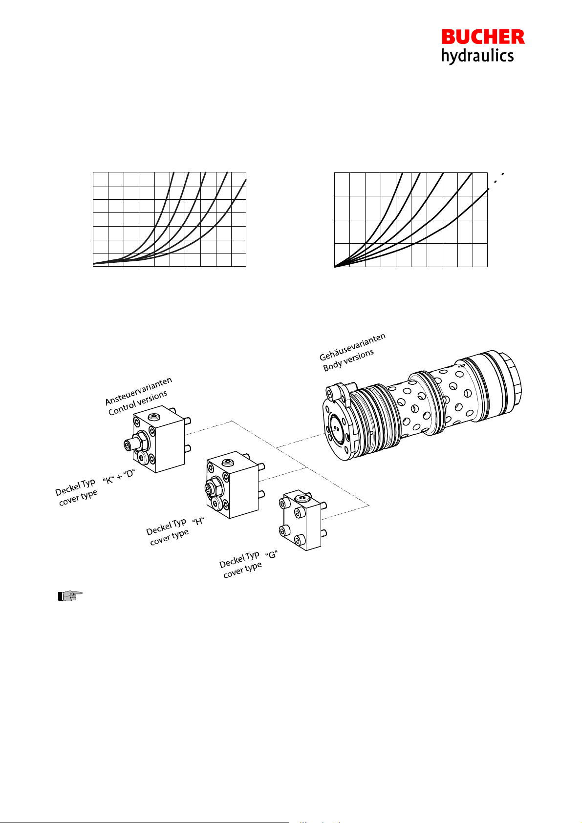
SVarious pilot-pressure ranges can be chosen
SAll exposed parts with zinc-nickel plating
SVarious types of pilot control, matched to your system,
can be supplied
SLow-noise operation thanks to specially shaped control
grooves
1 Description
Whenever large loads are to be precisely moved, placed
and held, when work access platforms must maintain their
position, or when hydraulic presses gates need to withstand
high forces, then CINDY load-control valves from Bucher
Hydraulics are the right solution.
Load-control valves in this series prevent hydraulic actua
tors from running ahead of the available oil supply.
In one valve, they combine the functions of load-holding,
safety and pipe-rupture protection. Leak-free load-control
valves in this series are ideally suited for use in high pres
sure applications up to 420 bar (6000 psi) with a safety fac
tor of at least 3.
With a variety of optional components, the range can be ex
tended and adapted to the requirements of the system.
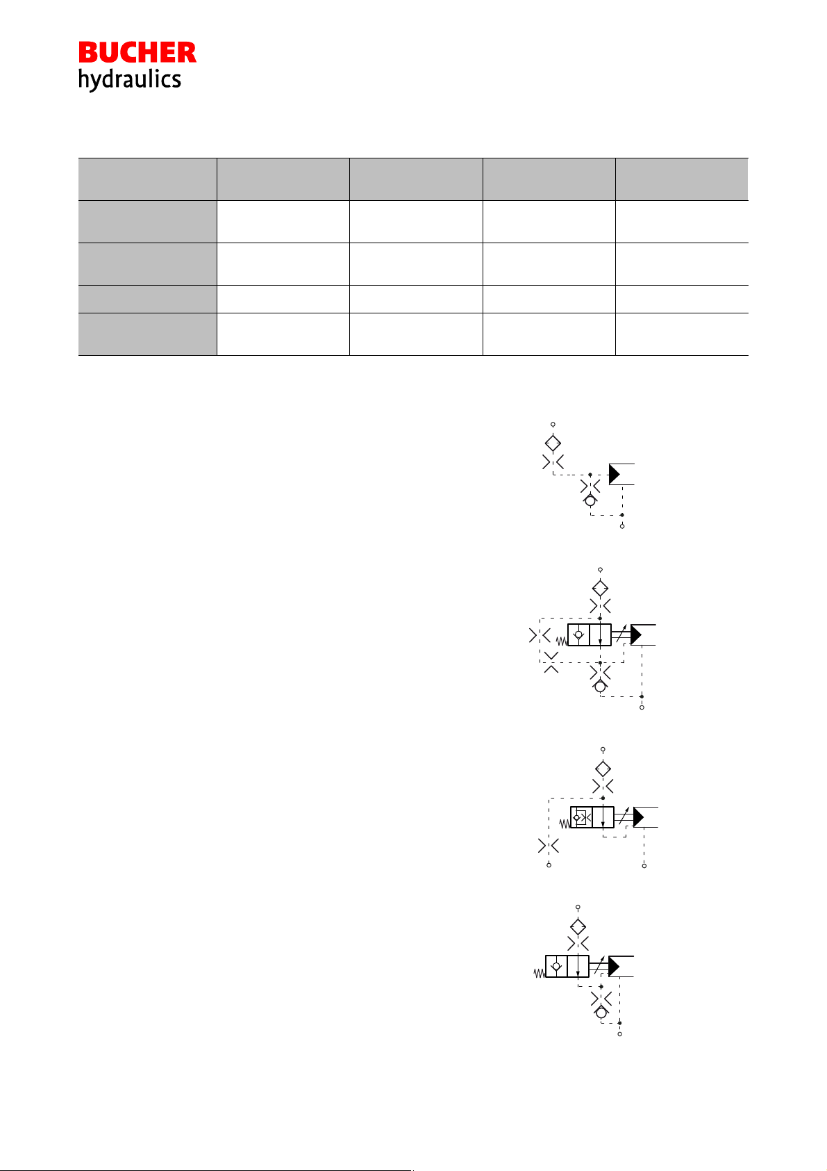
2 Symbol
Variant A
Influenced by return-line pressure
(pressure in A is additive to opening pilot pressure).
ABX
siehe Ansteuerungsvarianten
see types of pilot control
Variant L
Not influenced by return-line pressure
(drain line is required).
ABX L
siehe Ansteuerungsvarianten
see types of pilot control