Bucher Hydraulics VF-iValve VF-i250 Series User manual

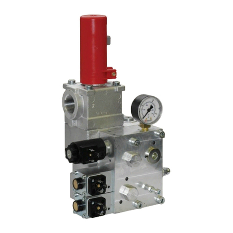
VF-iValve Lift Control Valve
2/33 300-I-9010546-EN-00/03.2015
E2015 by Bucher Hydraulics AG, CH-6345 Neuheim
All rights reserved. This documentation, in whole and/or in part, is protected by copyright. It may no
t
be reproduced, nor may it be stored, processed, replicated or distributed by electronic means, withou
t
written permission from Bucher Hydraulics.
Data is provided for the purpose of product description only, and must not be construed as warrante
d
characteristics in the legal sense. No assertion regarding either a particular property or the fitnes
s
for a particular intended purpose can be derived or deduced from this information. The informatio
n
does not relieve users from the duty of conducting their own evaluations and tests.
Because the products are subject to continual improvement, we reserve the right to amend the pro
duct specifications contained in this catalogue. The original language and legal terminology of all Bu
cher Hydraulics documentation is exclusively German. Bucher Hydraulics cannot be held liable fo
r
any possible errors in translation.
Published by
Bucher Hydraulics AG
Industriestrasse 15
CH-6345 Neuheim
Phone +41 41 757 03 33
Fax +41 41 757 05 00
Email [email protected]
Internet www.bucherhydraulics.com
Classification: 430.310.501
Issue: 09.2015
2/33
Reference: 300-I-9010546-EN-00

VF-iValve Lift Control Valve
3/33
300-I-9010546-EN-00/03.2015
Contents Page
1 About this document 5
.................................................................
1.1 Scope 5
.......................................................................
1.2 Target group 5
..................................................................
1.3 Other applicable documents 5
....................................................
1.4 Specialist terms 5
...............................................................
2 Safety instructions 6
...................................................................
2.1 Description of the safety notices 6
.................................................
2.1.1 Meaning of the signal words 6
.............................................
2.1.2 Meaning of the pictograms 6
..............................................
2.1.3 Example of asafety notice 7
..............................................
2.2 Basic principles 7
...............................................................
2.3 General safety instructions 7
.....................................................
2.3.1 Intended use 7
..........................................................
2.3.2 Operator's obligations 8
...................................................
2.3.3 Duties of the operating staff 8
..............................................
3 Product description 9
..................................................................
3.1 Intended use 9
.................................................................
3.1.1 Conformity 9
............................................................
3.2 Product identification 9
..........................................................
4 Construction and function 10
............................................................
4.1 Factory settings 10
...............................................................
5 Operating controls and indicators 11
......................................................
5.1 VF-iValve lift control valve 11
......................................................
5.1.1 Components of the VF-iValve –VF-i250 11
...................................
5.1.2 Components of the VF-iValve –VF-i500 12
...................................
5.2 Hand pump /Emergency lowering 13
...............................................
5.3 Electronic card iCon with VF-board 15
..............................................
5.3.1 LED indications 16
........................................................
5.3.2 LED indications (options board –switching outputs) 18
.........................
5.3.3 LED indications (options board –VF) 18
.....................................
6 Installation and commissioning 19
........................................................
6.1 Safety information 19
.............................................................
Issue: 09.2015
3/33
Reference: 300-I-9010546-EN-00

VF-iValve Lift Control Valve
4/33 300-I-9010546-EN-00/03.2015
6.1.1 Surroundings 19
..........................................................
6.2 Assembly 19
....................................................................
6.2.1 Hose or pipe 19
...........................................................
6.2.2 Electrical installation 20
....................................................
6.2.3 Installation of the ParamCard 21
............................................
6.2.4 Hydraulic fluids and oil additives 23
.........................................
6.2.5 Positioning of the deceleration switches 24
...................................
6.2.6 Check/setting of the max. operating pressure (EN 81-2, art. 12.5.3) 24
...........
6.3 Safety checks 25
................................................................
6.3.1 Test of the monitoring of the UCM/A3-valve 25
................................
6.3.2 Pipe rupture valve test 27
..................................................
7 Maintenance 29
.......................................................................
7.1 Maintenance schedule 29
.........................................................
7.2 Maintenance work 30
.............................................................
7.2.1 Pilot filter 30
..............................................................
7.2.2 Cleaning/replacing the VF-i250 pilot filter 30
..................................
7.2.3 Cleaning/replacing the VF-i500 pilot filter 30
..................................
8 Repair 33
.............................................................................
8.1 Troubleshooting and clearing faults 33
..............................................
Issue: 09.2015
4/33
Reference: 300-I-9010546-EN-00

VF-iValve Lift Control Valve 1 About this document
5/33
300-I-9010546-EN-00/03.2015
1 About this document
This commissioning and maintenance manual provides the basis for us
ing the lift control valve VF-iValve – VF-i250 / VF-i500 and iCon elec
tronic card for its intended purpose in a proper, effective, and safe
manner. This manual must be accessible to the commissioning and ser
vice personnel.
1.1 Scope
This manual is:
Sa part of the lift-control VF-iValve / iCon for commissioning and main
tenance
Sapplicable to the valve and all components referred to, such as the
iCon, Handterminal, iWIN, power supply unit and their connectors
and cables.
1.2 Target group
This commissioning and maintenance manual provides commissioning
and service personnel with all the information required for installation
and commissioning.
1.3 Other applicable documents
Reference No. Definition
300-P-9010073 Recommended hydraulic fluids
300-D-9010545 Planning information VF-iValve
300-P-9010553 Data sheet for handterminal
300-I-9010531 Parametrisation and Maintanance Manual
ESVH 018 Type examination certificate
300-S-9010554 Service manual for iBox
300-S-9010547 Spare parts VF-iValve i250
300-S-9010459 Spare parts VF-iValve i250
IMPORTANT!: These and other documents can be found in the
LOGintern section of our website
www.bucherhydraulics.com
1.4 Specialist terms
Term Definition
VF-iValve Intelligent lift control valve
iCon Electronic control card for VF-iValve valve
Handterminal Terminal (optional) for the parameterisation of the VF-iValve
iWIN PC-software (optional) for the parameterisation of the
VF-iValve
iBox Sensor unit in the VF-iValve
iTeach Program on the iCon
ParamCard Memory card
SMA Monitoring of the UCM/A3-valve
(“Self Monitoring Acknowledgement”)
Issue: 09.2015
5/33
Reference: 300-I-9010546-EN-00

VF-iValve Lift Control Valve2 Safety instructions
6/33 300-I-9010546-EN-00/03.2015
2 Safety instructions
This documentation (manual) advises the user of the dangers and re
maining risks that can arise even when the product is being used pro
perly and for its intended purpose. It is essential to take note of the sa
fety instructions in each section.
2.1 Description of the safety notices
This commissioning and maintenance manual contains safety informa
tion for the safe operation of the product. Dangers and residual risks are
signalled with the following elements:
2.1.1 Meaning of the signal words
The table below shows the meaning of the signal words that are used to
identify the different levels of danger.
Signal words Meaning
DANGER! This denotes a directly imminent danger. If it is not at
tended to, it will result in death or serious injuries to
people.
WARNING! Denotes a potentially dangerous situation. If it is not
prevented, it may result in death or serious injuries to
people.
CAUTION! Denotes a potentially dangerous situation. If it is not
prevented, it may result in slight or minor injuries to
people.
ATTENTION! Denotes a potentially harmful situation. If it is not pre
vented, the product or its surroundings may be dama
ged.
2.1.2 Meaning of the pictograms
The following pictograms are used as warning symbols. They are com
bined with the appropriate signal word, depending on the danger level.
Meaning
This warning symbol is used in conjunction with the
signal words "DANGER", "WARNING" or "CAU
TION".
Warning of dangerous electrical voltage.
This warning symbol is used exclusively in conjunc
tion with the signal word "WARNING".
This warning symbol indicates the risk of a large po
tential difference (ESD).
Issue: 09.2015
6/33
Reference: 300-I-9010546-EN-00
VF-iValve Lift Control Valve 2 Safety instructions
7/33
300-I-9010546-EN-00/03.2015
2.1.3 Example of a safety notice
SPictogram
SSignal word
SType and source of danger
SPossible consequences of the danger
SMeasures for preventing the danger
WARNING!
Dangerous electrical voltage
Touching electrical components may result in serious injury or
death. During installation or repair work, ensure that the power
supply is interrupted.
2.2 Basic principles
The intelligent lift control valve VF-iValve is an electronically controlled
hydraulic valve block for controlling hydraulic lifts. The VF-iValve is situ
ated on the hydraulic power unit and activated by the lift control system.
2.3 General safety instructions
ATTENTION!
Take note of the following instructions before carrying out any
work.
2.3.1 Intended use
The Lift Control Valve has been built in accordance with the state of the
art and recognised safety regulations. Nevertheless, risks to the life and
limb of users or third parties may arise during its use, or damage to the
car frame kit or other material assets may result.
SKeep this manual and all other applicable documents complete and
legible, and accessible to all personnel at all times
SDo not work in any manner that endangers personnel or uninvolved
third parties
SIf there is a safety-related fault, shut down the Lift Control Valve im
mediately and have the fault rectified by a competent person
SIn addition to the entire documentation for the product, always com
ply with statutory or other safety and accident-prevention rules as
well as with the applicable standards and guidelines in the country
where the valve is operated
Issue: 09.2015
7/33
Reference: 300-I-9010546-EN-00
VF-iValve Lift Control Valve2 Safety instructions
8/33 300-I-9010546-EN-00/03.2015
2.3.2 Operator's obligations
Working with safety in mind
SOnly operate the valve if it is in perfect technical condition; only use it
as intended, staying aware of safety and risks, and adhearing to the
instructions in this manual
SEnsure that the following are observed and monitored:
- adherence to intended use
- statutory or other safety and accident-prevention rules
- safety regulations governing the handling of hazardous sub
stances
- applicable standards and guidelines in the country where the valve
is operated
SMake protective equipment available
Staff qualifications
SEnsure that all personnel tasked with work on the valve have read
and understood this manual and all other applicable documents, es
pecially the safety, maintenance and repair instructions, before they
begin the job
SOrganize responsibilities, who is in charge of any specific duty and
how personnel are supervised
SEnsure that all work is carried out by specialist technicians only:
- fitting, repair and maintenance work
- work on the valve electrical system
Warranty
SObtain the manufacturer's approval prior to carrying out any modifica
tion, repair or alterations during the warranty period
2.3.3 Duties of the operating staff
SObserve and keep legible all instructions given on the Lift Control
Valve, e.g. the arrow indicating the direction of rotation and the
markings for fluid connections
SCarry out work on the Lift Control Valve only while the motor is not
running
SIsolate the motor from its supply voltage and keep it locked in that
state while carrying out any fitting or maintenance work
Issue: 09.2015
8/33
Reference: 300-I-9010546-EN-00

VF-iValve Lift Control Valve 3 Product description
9/33
300-I-9010546-EN-00/03.2015
3 Product description
3.1 Intended use
The VF-iValve intelligent lift control valve is an electronically controlled
hydraulic valve block for controlling hydraulic lifts. The VF-iValve is situ
ated on the hydraulic power unit and activated by the lift control system.
Electronic control is accomplished by an electronic unit – the iCon – that
is housed in the control cabinet. At standstill, the weight of the lift is sup
ported by a check valve integrated in the VF-iValve. In operation, the
electronic controller regulates the three states "Bypass", "Travel UP"
and "Travel DOWN", and the transitions between them. In the electronic
unit, this travel is represented in a form known as travel curves. During
operation, the travel curves for that particular lift are optimised by the
learning algorithm "iTeach". In addition, the valve block includes the fol
lowing functions and components: a hand pump with manual emergency
lowering (with piston-creep prevention), a ball valve, a pressure gauge,
a pressure sensor with up to two pressure switches, speed monitoring, a
temperature sensor, a UCM/A3 valve in accordance with EN 81-2 + A3.
3.1.1 Conformity
The product was designed and developed in conformity with the follow
ing directives and standards:
EC-directive 2006/42/EG
EC-directive 95/16/EG
Standards EN81-2:1998+A3:2009
Safety rules for hydraulic lifts
Standards EN12015:2014, EN 12016:2013
(Electromagnetic compatibility for lifts)
3.2 Product identification
The lift control valve has a stuck-on nameplate with the following infor
mation:
1. Valve type
2. Certificate no.
3. Month / year
4. Serial number
Issue: 09.2015
9/33
Reference: 300-I-9010546-EN-00

VF-iValve Lift Control Valve4 Construction and function
10/33 300-I-9010546-EN-00/03.2015
4 Construction and function
IMPORTANT!: Information on schematics and diagrams is avail
able in the VF-iValve Planning Information (300-D-9010545).
4.1 Factory settings
Installation specific settings are stored on the ParamCard:
SKit type
SCylinder type and diameter
SMax. speed UP and DOWN
SDeceleration distance acc. to diagram
STravel curve settings
SOther settings
Issue: 09.2015
10/33
Reference: 300-I-9010546-EN-00

VF-iValve Lift Control Valve 5 Operating controls and indicators
11/33
300-I-9010546-EN-00/03.2015
5 Operating controls and indicators
5.1 VF-iValve lift control valve
5.1.1 Components of the VF-iValve – VF-i250
300-7-10026200--
7
C
Z1
Z
P
T
T2
8
6
3
10
5
11
12
4
9
1
2
HP
5
6
27
13
Legend 1
2
3
4
5
6
7
8
9
10
Solenoid UP/DOWN
Pressure relief valve
Ball valve
Solenoid UCM / A3
Slack rope safety device
Hand pump/emerg. lowering
Pressure relief valve for the
hand pump
Handle for hand pump (sup
plied loose)
Pressure gauge
Solenoid VF-Emergency stop
valve
11
12
13
C
P
T
HP
T2
Z
Z1
Connection, sensor cable iBox
LED
Nameplate
iBox
Pump port
Tank port
Tank port, hand pump /
emergency lowering
Pilot oil port
Cylinder port
Port for relevelling / test port
Issue: 09.2015
11/33
Reference: 300-I-9010546-EN-00

VF-iValve Lift Control Valve5 Operating controls and indicators
12/33 300-I-9010546-EN-00/03.2015
5.1.2 Components of the VF-iValve – VF-i500
Z
HP
T
P
4
2
3
9
8
5
6
C
7
300-4-10024900
Z1
41
6
4
10
1
11
12
T2
Legend 1
2
3
4
5
6
7
8
9
10
Solenoid UP/DOWN
Pressure relief valve
Ball valve
Solenoid UCM / A3
Hand pump
Pressure relief valve for the
hand pump
Pressure gauge
Connection, sensor cable iBox
LED
11
12
C
P
T
HP
T2
Z
Z1
Nameplate
Emergency-lowering
valve
Solenoid VF-Emergency stop
valve
iBox
Pump port
Tank port
Tank port, hand pump
Pilot oil Port
Cylinder port
Port for relevelling / test port
Issue: 09.2015
12/33
Reference: 300-I-9010546-EN-00

VF-iValve Lift Control Valve 5 Operating controls and indicators
13/33
300-I-9010546-EN-00/03.2015
5.2 Hand pump / Emergency lowering
VF-iValve – VF-i250
The VF-iValve (VF-i250) comes with a combination of hand pump and
emergency lowering valve as standard.The car can be moved upward
with the hand pump when needed, and downward by means of the
emergency-lowering facility.
Operating the hand pump
Achtung
Caution
1. Push the extension lever onto the lever stub of the hand pump as
far as it will go.
2. Swing the hand pump lever up and down
Operating the emergency lowering
DANGER!
Car descent
Can lead to death or serious injuries.
Before operating the emergency-lowering valve, make sure that
there are no people or materials in the lift shaft.
Achtung
90°
1
2
3007019379
3
Caution
1. Push the extension lever onto the lever stub of the hand pump as
far as it will go, then retract by approx. 3cm
2. Push the hand pump lever down
Temporary deactivation of piston slack rope safety device
(preload pressure)
In order to prevent slack-rope build-up as per EN81-2 no. 12.9.1.5
operation of the emergency lowering valve will leave a preload pressure
of 6bar.
In order to temporarily deactivate the preload pressure:
3. Turn the slack rope safety device (1) by 90° clockwise.
4. Push the hand pump lever down (with extension lever) until the
pressure is completely relieved
5. Turn the slack rope safety device (1) by 90° anticlockwise to the
original position
Issue: 09.2015
13/33
Reference: 300-I-9010546-EN-00

300−7−10024540
1
VF-iValve Lift Control Valve5 Operating controls and indicators
14/33 300-I-9010546-EN-00/03.2015
VF-iValve – VF-i500
In the VF-iValve i500, the hand pump and emergency-lowering facility
are separated. The car can be moved upward with the hand pump when
needed, and downward by means of the emergency-lowering facility.
Hand pump
Emergency lowering
DANGER!
Car descent
Can lead to death or serious injuries.
Before operating the emergency-lowering valve, make sure that
there are no people or materials in the lift shaft.
The car is lowered by pressing the lever of the emergency-lowering
valve.
Note: The minimum preload pressure of 6bar remains
(prevents slack-rope build-up as per EN81-2, sect. 12.9.1.5).
Temporary deactivation of preload pressure
For the purpose of checks or maintenance the preload pressure can be
temporarily deactivated.
If no other M3-screw is ready to hand:
1. Remove the fastening screw from a solenoid plug
2. Screw the M3-screw into the opening (1) of the lever of the
emergency-lowering valve
In order to deactivate the preload pressure:
3. Pull the M3-screw and simultaneously press the lever of the
emergency-lowering valve
4. Undo the M3-screw from the lever of the emergency lowering
If the M3-screw had been undone from the solenoid plug:
5. Screw the M3-screw back into the solenoid plug
Issue: 09.2015
14/33
Reference: 300-I-9010546-EN-00

VF-iValve Lift Control Valve 5 Operating controls and indicators
15/33
300-I-9010546-EN-00/03.2015
5.3 Electronic card iCon with VF-board
ATTENTION!
Electrostatic discharge (ESD)
The iCon can be damaged by incorrect handling.
Always keep the iCon in its ESD protective bag and only hold it
by the frame.
1
1
11
1
X10 X6X7 X5 X4
12345 678
GND
GND
GND
m0(9) m1(10)
-+ -+ com/meas
1
X1 1
X2
RS232
X3
ok
select
pwr
run
up
down
misc.
X8
X9
300−P−10025071−00
error
s1
s2
card
X8 X4X5
X6X7
X10
X3
2
1
X2
X1
X9
3
4
5
5
5
6
X30
Item Description Item Description
1 ParamCard X4 Connection, iBox
2Top-hat rail TS15, TS35 (EN50022) or
G-type rail G32 (EN50035)
X5 Connector block, solenoids
3Push button ok X6 Connector block, command signals K6…K8
4Push button select X7 Connector block, command signals K1…K5
5 LEDs X8 Socket for ParamCard
6 VF-board X9 Socket for options boards
X1 Connector block, power supply X10 Connector block, SMA
X2 Connector block, switching outputs X30 Connector inverter (on VF-board)
X3 Connection, Handterminal / PC
Issue: 09.2015
15/33
Reference: 300-I-9010546-EN-00

VF-iValve Lift Control Valve5 Operating controls and indicators
16/33 300-I-9010546-EN-00/03.2015
5.3.1 LED indications
LED Description
Status
Function
com Communication with
valve
on communication with valve ok, data packages properly
transmitted/received
flashes ra
pidly
no (correct) communication with valve
meas Measurement of feed
back values
on feedback values from valve (flow, pressure, temperature)
plausible
off when LED “com” flashes rapidly simultaneously: no correct
communication with valve
flashes
rapidly
feedback values from valve (flow, pressure, temperature)
not plausible, zero point outside permissible range
flashes
slowly
versions of iCon and iBox not compatible with each other
or
error during function/EEPROM access on valve
m1(10) Solenoid UP/DOWN on solenoid actuated, current correct
off solenoid not actuated
flashes ra
pidly
solenoid actuated, resistance not correct
flashes
slowly
current not correct
m0(9) Solenoid
UCM/A3
on solenoid actuated, current correct
off solenoid not actuated
flashes ra
pidly
solenoid actuated, resistance not correct
flashes
slowly
current not correct
8Command input 8 on command signal K8 present
7Command input 7 on command signal K7 present
6Command input 6 on command signal K6 present
5Command input 5 on command signal K5 present
4Command input 4 on command signal K4 present
3Command input 3 on command signal K3 present
2Command input 2 on command signal K2 present
1Command input 1 on command signal K1 present
+SMA Monitoring of
UCM/A3-valve
on terminal +SMA (X10-2) supplies +24V
Issue: 09.2015
16/33
Reference: 300-I-9010546-EN-00

VF-iValve Lift Control Valve 5 Operating controls and indicators
17/33
300-I-9010546-EN-00/03.2015
Function
Status
DescriptionLED
pwr Power supply on all monitored voltages within the permissible range
flashes ra
pidly
one of the internally generated voltages outside the permis
sible range
flashes
slowly
external supply voltage (+24V) outside the permissible
range
run Readiness for opera
tion
on program running, ready for travel
off not ready for travel
flashes
slowly
not ready for travel, error while starting the program (e.g.
EEPROM could not be read), incorrect parameters, param
eter synchronisation running (during start, can take up to
10s)
up Travel UP on travel UP
down Travel DOWN on travel DOWN
flashes pipe rupture test activated
misc iTeach on All iTeach functions on and operating in the permissible
range
off All iTeach functions off
flashes
slowly
At least one iTeach function has reached correction limit
on for
8…9s,
then inter
rupted for
an instant
Indication of deactivated iTeach-functions (number of inter
ruptions = number of
deactivated iTeach-functions)
card ParamCard on ParamCard plugged in, with plausible data
flashes ra
pidly
no ParamCard detected
flashes
slowly
data not plausible
error Error flashes
rapidly
Error present (error relay is energised; list of error mes
sages
s1 Switching output 1 flashes
rapidly
Switching point 1 under-run or exceeded (relay s1 is ener
gised)
s2 Switching output 2 flashes
rapidly
Switching point 2 under-run or exceeded (relay s2 is ener
gised)
Issue: 09.2015
17/33
Reference: 300-I-9010546-EN-00

VF-iValve Lift Control Valve5 Operating controls and indicators
18/33 300-I-9010546-EN-00/03.2015
5.3.2 LED indications (options board – switching outputs)
LED Description Status Function
RUN Readiness for operation on program running correctly
off programm not running correctly
flashes communication problem with iCon
s3 Switching output 3 flashes
rapidly
switching point 3 was under-shot/ ex
ceeded
(relay s3 energised)
s4 Switching output 4 flashes
rapidly
switching point 4 was under-shot/ ex
ceeded
(relay s4 energised)
5.3.3 LED indications (options board – VF)
LED Description Status Function
RUN Readiness for operation on programm running correctly
off programm not running correctly
flashes communication problem with iCon
RDY Ready for operation FU on inverter signals ready
flashes unexpected ready status
EN Inverter enable on inverter receives enable signal
TRQ Motor energised on inverter signals that motor is energised
flashes unexpected motor-energisation status
ANA
OUT +
Positive speed setting on lights when speed is positive
(intensity depends on setting)
ANA
OUT -
Negative speed setting on lights when speed is negative
(intensity depends on setting)
Issue: 09.2015
18/33
Reference: 300-I-9010546-EN-00

VF-iValve Lift Control Valve 6 Installation and commissioning
19/33
300-I-9010546-EN-00/03.2015
6 Installation and commissioning
Packaging materials must be disposed of in accordance with the gener
ally recognised regulations of the respective countries
6.1 Safety information
Before beginning any installation and commissioning work, it is a re
quirement that all personnel have read and understood the chapter
"Safety instructions".
6.1.1 Surroundings
For reliable operation, the following conditions must be maintained in
the surroundings:
General characteristics Description, value, unit
Machine room temperature +2°C … +40°C
Relative air humidity max. 90% (non-condensing)
6.2 Assembly
6.2.1 Hose or pipe
CAUTION!
Contamination in the line
Contamination adversely affects the valve's function. This can
lead to a dangerous system condition.
Preventive measures:
SClean the hose or pipe before fitting it
SLeave sealing caps/plugs in place until assembly
SCheck that all fittings are assembled correctly
SDo not twist the hoses
SDo not mount hoses under tensile strain
SObserve minimum bending radiuses
SProtect hoses against mechanical damage (e.g. from sharp edges)
SSupport hoses with hose clamps (approx. 1.5m away from valve)
Issue: 09.2015
19/33
Reference: 300-I-9010546-EN-00

300−7−10024900−B
A
B
C
Erdungsband
ground strap
VF-iValve Lift Control Valve6 Installation and commissioning
20/33 300-I-9010546-EN-00/03.2015
6.2.2 Electrical installation
DANGER!
Dangerous voltage
Leads to death or serious injuries.
Before starting electrical installation works, disconnect all power
to the control cabinet.
1. Check whether the 24VDC output of the lift control meets the
requirements of the iCon (see Planning Information
300-D-9010545)
When the 24VDC output of the lift control meets the requirements of
the iCon:
2. Execute the cabling acc. to the diagram (see Planning Information
300-D-9010545)
IPlug the grey connector (A) onto the solenoid UP/DOWN,
plug the black connector (B) onto the solenoid UCM/A3
To reduce electromagnetic interference fields and for trouble-free opera
tion, the VF-iValve valve block must also be separately earthed:
3. Using an earth conductor with a minimum crosssection of
4 mm², create a connection from the valve block to the earth poten
tial in the control cabinet. Run the wiring as per the diagram (see
Planning Information 300-D-9010545 ).
IThe earth connection on the valve block is clearly identified, but can also
be seen in the leaflet 300-D-9010545, Chapter 3.2.3.
When the 24VDC output of the lift control does NOT meet the require
ments of the iCon:
4. Install the optionally available power supply unit and execute the
wiring acc. to the diagram (see Planning Information
300-D-9010545)
IPlug the grey connector (A) onto the solenoid UP/DOWN,
plug the black connector (B) onto the solenoid UCM/A3
ATTENTION!
Unexpected behaviour of the lift
Air in the VF-iValve can cause unexpected behaviour of the lift
such as
- severe starting jolt UP
- no start DOWN
Make sure that the connections between the VF-iValve and the
tube to the pump(P) as well as the hoses to the tank(T, T1) are
tight and that there will be no venting and hence draining of the
tube or of the hoses.
B
300−7−10026200−F
AC
Erdungsband
ground strap
Issue: 09.2015
20/33
Reference: 300-I-9010546-EN-00
This manual suits for next models
1
Table of contents
Other Bucher Hydraulics Control Unit manuals