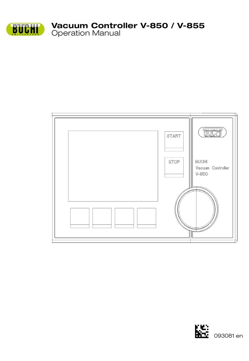
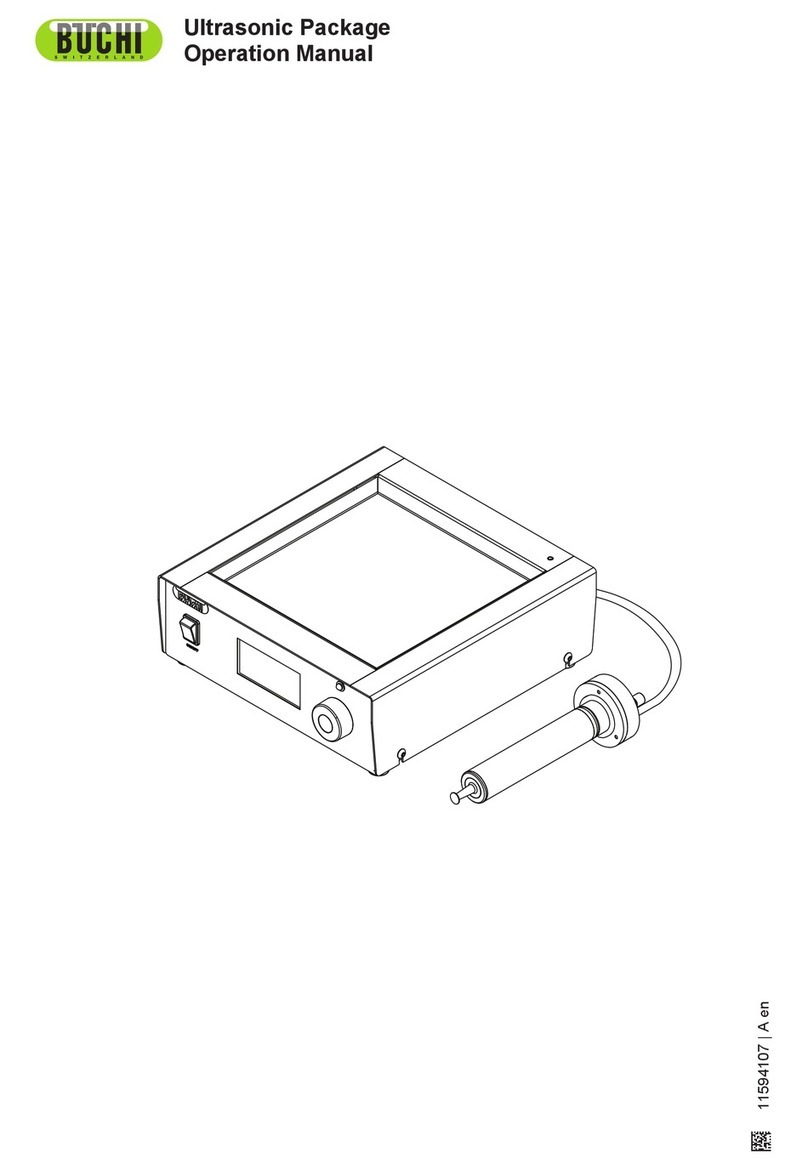
Buchi V-850 User manual

Operation Manual
93081
en
V-850/855
Vacuum Controller


Table of contents
3V-850/855 Operation Manual, Version A
Table of contents
1 About this manual . . . . . . . . . . . . . . . . . . . . . . . . . . . . . . . . . . . . . . . 5
1.1 Reference documents. . . . . . . . . . . . . . . . . . . . . . . . . . . . . . . . . . 5
1.2 Trademarks . . . . . . . . . . . . . . . . . . . . . . . . . . . . . . . . . . . . . . . 5
1.3 Abbreviations . . . . . . . . . . . . . . . . . . . . . . . . . . . . . . . . . . . . . . 5
2 Safety. . . . . . . . . . . . . . . . . . . . . . . . . . . . . . . . . . . . . . . . . . . . . . 6
2.1 User qualification . . . . . . . . . . . . . . . . . . . . . . . . . . . . . . . . . . . . 6
2.2 Proper use . . . . . . . . . . . . . . . . . . . . . . . . . . . . . . . . . . . . . . . 6
2.3 Improper use . . . . . . . . . . . . . . . . . . . . . . . . . . . . . . . . . . . . . . 6
2.4 Warning notices used in this manual . . . . . . . . . . . . . . . . . . . . . . . . . . 7
2.5 Product safety. . . . . . . . . . . . . . . . . . . . . . . . . . . . . . . . . . . . . . 7
2.6 General safety rules . . . . . . . . . . . . . . . . . . . . . . . . . . . . . . . . . . . 8
3 Technical data . . . . . . . . . . . . . . . . . . . . . . . . . . . . . . . . . . . . . . . . . 9
3.1 Scope of delivery . . . . . . . . . . . . . . . . . . . . . . . . . . . . . . . . . . . . 9
3.1.1 Basic instrument . . . . . . . . . . . . . . . . . . . . . . . . . . . . . . . . . . . . 9
3.1.2 Standard accessories . . . . . . . . . . . . . . . . . . . . . . . . . . . . . . . . . 10
3.1.3 Optional accessories . . . . . . . . . . . . . . . . . . . . . . . . . . . . . . . . . 10
3.2 Technical data overview . . . . . . . . . . . . . . . . . . . . . . . . . . . . . . . . 13
3.3 Materials used. . . . . . . . . . . . . . . . . . . . . . . . . . . . . . . . . . . . . 13
3.4 Solvent table . . . . . . . . . . . . . . . . . . . . . . . . . . . . . . . . . . . . . 14
4 Description of function . . . . . . . . . . . . . . . . . . . . . . . . . . . . . . . . . . . 15
4.1 Functional principle . . . . . . . . . . . . . . . . . . . . . . . . . . . . . . . . . . 15
4.1.1 Control keys of Vacuum Controller V-850/855. . . . . . . . . . . . . . . . . . . . . 15
4.1.2 Rear connections . . . . . . . . . . . . . . . . . . . . . . . . . . . . . . . . . . . 16
4.2 Controller operation modes . . . . . . . . . . . . . . . . . . . . . . . . . . . . . . 16
4.2.1 Manual mode . . . . . . . . . . . . . . . . . . . . . . . . . . . . . . . . . . . . . 16
4.2.2 Timer mode . . . . . . . . . . . . . . . . . . . . . . . . . . . . . . . . . . . . . . 16
4.2.3 AutoDest mode (V-855 only). . . . . . . . . . . . . . . . . . . . . . . . . . . . . . 16
4.2.4 EasyVac mode (V-855 only) . . . . . . . . . . . . . . . . . . . . . . . . . . . . . . 17
4.2.5 Gradient mode (V-855 only) . . . . . . . . . . . . . . . . . . . . . . . . . . . . . . 17
4.2.6 Repeat mode (V-855 only). . . . . . . . . . . . . . . . . . . . . . . . . . . . . . . 17
4.2.7 LabVac mode (V-855 only) . . . . . . . . . . . . . . . . . . . . . . . . . . . . . . 18
Read this manual carefully before installing and running your system and note the safety precautions
in chapter 2 in particular. Store the manual in the immediate vicinity of the instrument, so that it can be
consulted at any time.
No technical modifications may be made to the instrument without the prior written agreement of
Buchi. Unauthorized modifications may affect the system safety or result in accidents.
This manual is copyright. Information from it may not be reproduced, distributed, or used for competi-
tive purposes, nor made available to third parties. The manufacture of any component with the aid of
this manual without prior written agreement is also prohibited.
If you need another language version of this manual, you can download it at
www.buchi.com.

Table of contents
4V-850/855 Operation Manual, Version A
5 Putting into operation . . . . . . . . . . . . . . . . . . . . . . . . . . . . . . . . . . . . 19
5.1 Setting up the Rotavapor with the Vacuum Controller V-850/855 . . . . . . . . . . . 19
5.1.1 Installation. . . . . . . . . . . . . . . . . . . . . . . . . . . . . . . . . . . . . . . 19
5.1.2 Cable connections to the Rotavapor . . . . . . . . . . . . . . . . . . . . . . . . . 20
5.2 Communication of Rotavapor and Vacuum Controller V-850/855 . . . . . . . . . . . 20
5.3 Installing the AutoDest probe . . . . . . . . . . . . . . . . . . . . . . . . . . . . . 21
5.4 Initial software settings . . . . . . . . . . . . . . . . . . . . . . . . . . . . . . . . 22
6 Operation . . . . . . . . . . . . . . . . . . . . . . . . . . . . . . . . . . . . . . . . . . 25
6.1 Menu structure of the Vacuum Controller V-850/855 software. . . . . . . . . . . . . 25
6.2 Vacuum Controller V-850/855 main screen in Manual mode. . . . . . . . . . . . . . 26
6.3 Selecting the distillation conditions . . . . . . . . . . . . . . . . . . . . . . . . . . 26
6.4 Starting a distillation . . . . . . . . . . . . . . . . . . . . . . . . . . . . . . . . . . 27
6.4.1 Quick start of manual destillation . . . . . . . . . . . . . . . . . . . . . . . . . . . 27
6.4.2 Advanced settings . . . . . . . . . . . . . . . . . . . . . . . . . . . . . . . . . . 29
6.5 Vacuum Controller V-850/855 main screen in Gradient mode . . . . . . . . . . . . . 30
6.6 General information on buttons . . . . . . . . . . . . . . . . . . . . . . . . . . . . 31
6.6.1 Control buttons . . . . . . . . . . . . . . . . . . . . . . . . . . . . . . . . . . . . 31
6.6.2 Menu buttons . . . . . . . . . . . . . . . . . . . . . . . . . . . . . . . . . . . . . 32
6.7 Main menu . . . . . . . . . . . . . . . . . . . . . . . . . . . . . . . . . . . . . . 32
6.7.1 Mode . . . . . . . . . . . . . . . . . . . . . . . . . . . . . . . . . . . . . . . . . 33
6.7.2 Options . . . . . . . . . . . . . . . . . . . . . . . . . . . . . . . . . . . . . . . . 33
6.7.3 Program. . . . . . . . . . . . . . . . . . . . . . . . . . . . . . . . . . . . . . . . 33
6.7.4 Solvent library . . . . . . . . . . . . . . . . . . . . . . . . . . . . . . . . . . . . . 35
6.7.5 Extra . . . . . . . . . . . . . . . . . . . . . . . . . . . . . . . . . . . . . . . . . 35
6.8 Calibrating the pressure sensor . . . . . . . . . . . . . . . . . . . . . . . . . . . . 37
6.8.1 Offset calibration . . . . . . . . . . . . . . . . . . . . . . . . . . . . . . . . . . . 38
6.8.2 Simple calibration (without temperature compensation) . . . . . . . . . . . . . . . . 38
6.8.3 Complete calibration with temperature compensation . . . . . . . . . . . . . . . . . 39
6.9 Tips and tricks for a distillation . . . . . . . . . . . . . . . . . . . . . . . . . . . . 41
6.9.1 What to do when the solvent starts foaming? . . . . . . . . . . . . . . . . . . . . . 41
6.9.2 How to find out the distillation conditions for a solvent? . . . . . . . . . . . . . . . . 41
6.9.3 How to start a distillation without determining a pressure setpoint? . . . . . . . . . . 41
7 Maintenance . . . . . . . . . . . . . . . . . . . . . . . . . . . . . . . . . . . . . . . . . 42
7.1 Housing . . . . . . . . . . . . . . . . . . . . . . . . . . . . . . . . . . . . . . . . 42
7.2 Functional test. . . . . . . . . . . . . . . . . . . . . . . . . . . . . . . . . . . . . 42
8 Troubleshooting . . . . . . . . . . . . . . . . . . . . . . . . . . . . . . . . . . . . . . . 43
8.1 Malfunctions and their remedy . . . . . . . . . . . . . . . . . . . . . . . . . . . . 43
8.2 Customer service . . . . . . . . . . . . . . . . . . . . . . . . . . . . . . . . . . . 44
9 Shutdown, storage, transport and disposal . . . . . . . . . . . . . . . . . . . . . . . . 45
9.1 Storage and transport . . . . . . . . . . . . . . . . . . . . . . . . . . . . . . . . . 45
9.2 Disposal. . . . . . . . . . . . . . . . . . . . . . . . . . . . . . . . . . . . . . . . 45
9.3 Health and safety clearance form . . . . . . . . . . . . . . . . . . . . . . . . . . . 46
10 Spare parts . . . . . . . . . . . . . . . . . . . . . . . . . . . . . . . . . . . . . . . . . 47
10.1 Spare parts . . . . . . . . . . . . . . . . . . . . . . . . . . . . . . . . . . . . . . 47
11 Declarations and requirements. . . . . . . . . . . . . . . . . . . . . . . . . . . . . . . 48
11.1 FCC requirements (for USA and Canada) . . . . . . . . . . . . . . . . . . . . . . . 48
11.2 Declaration of conformity . . . . . . . . . . . . . . . . . . . . . . . . . . . . . . . 49

1 About this manual
5V-850/855 Operation Manual, Version A
1 About this manual
This manual describes the vacuum controller and provides all information required for its safe opera-
tion and to maintain it in good working order.
It is adressed in particular to laboratory personnel and operators.
NOTE:
The symbols pertaining to safety (WARNINGS and ATTENTIONS) are explained in chapter 2.
1.1 Reference documents
For information on the Rotavapor R-210/215 and the Vacuum Pump V-700/710, please refer to the
corresponding manuals available in English, German, French, Spanish and Italian:
Rotavapor R-210/215, Operation Manual numbers 93076–93080
Vacuum Pump, Operation Manual numbers 93090–93094
1.2 Trademarks
The following product names and any registered and unregistered trademarks mentioned in this
manual are used for identification purposes only and remain the exclusive property of their respective
owners:
Rotavapor® is a registered trademark of Büchi Labortechnik AG
Teflon® is a registered trademark of DuPont or its affiliates
Kalrez®is a registered trademark of DuPont
1.3 Abbreviations
PBT: Polybutylene Terephthalate
PES: Polyester
PVC: Polyvinyl chloride
PEEK: Polyetheretherketone
•
•
•
•
•

2 Safety
6V-850/855 Operation Manual, Version A
2 Safety
This chapter points out the safety concept of the instrument and contains general rules of behavior
and warnings from hazards concerning the use of the product.
The safety of users and personnel can only be ensured if these safety instructions and the safety-
related warnings in the individual chapters are strictly observed and followed. Therefore, the manual
must always be available to all persons performing the tasks described herein.
2.1 User qualification
The instrument may only be used by laboratory personnel and other persons who on account of
training or professional experience have an overview of the dangers which can develop when
operating the instrument.
Personnel without this training or persons who are currently being trained require careful instruction.
The present Operation Manual serves as the basis for this.
2.2 Proper use
This instrument has been designed and built for laboratories. Its proper use includes regulating and
displaying a vacuum in a working range between 0 mbar up to atmospheric pressure.
The vacuum controller is used for:
Distillation instruments, especially rotary evaporators
Vacuum drying cabinets
2.3 Improper use
Applications not mentioned above are improper. Also, applications, which do not comply with the
technical data, are considered improper. The operator bears the sole risk for any damages caused by
such improper use.
The following uses are expressly forbidden:
Use of the instrument in rooms which require ex-protected instruments.
Use as calibrating instrument for other instruments.
Use in excess pressure.
•
•
•
•
•

2 Safety
7V-850/855 Operation Manual, Version A
2.4 Warning notices used in this manual
WARNING
Generally, the triangular warning symbol indicates the possibility of personal injury or even loss of life
if the instructions are not followed.
WARNING
Hot surface.
ATTENTION
With the general “Read this” symbol, ATTENTIONs indicate the possibility of equipment damage,
malfunctions or incorrect process results, if instructions are not followed.
NOTE
Useful tips for the easy operation of the instrument.
2.5 Product safety
The vacuum controller is designed and built in accordance with current state-of-the-art technology.
Nevertheless, risks to users, property, and the environment can arise when the instrument is used
carelessly or improperly.
The manufacturer has determined residual dangers emanating from the instrument
if the instrument is operated by insufficiently trained personnel.
if the instrument is not operated according to its proper use.
Appropriate warnings in this manual serve to make the user alert to these residual dangers.
WARNING
Electromagnetic radiation may affect the pressure measurement so that the measured pressure value
can be adulterated.
Keep the instrument from the influence of electromagnetic radiation.
•
•
•

2 Safety
8V-850/855 Operation Manual, Version A
2.6 General safety rules
Responsibility of the operator
The head of laboratory is responsible for training his personnel.
The operator shall inform the manufacturer without delay of any safety-related incidents which might
occur during operation of the instrument. Legal regulations, such as local, state and federal laws
applying to the instrument must be strictly followed.
Duty of maintenance and care
The operator is responsible for ensuring that the instrument is operated in proper condition only, and
that maintenance, service, and repair jobs are performed with care and on schedule, and by autho-
rized personnel only.
Spare parts to be used
Use only genuine consumables and genuine spare parts for maintenance to assure good system
performance and reliability. Any modifications to the spare parts used are only allowed with the prior
written permission of the manufacturer.
Modifications
Modifications to the instrument are only permitted after prior consultation with and with the written
approval of the manufacturer. Modifications and upgrades shall only be carried out by an authorized
Buchi technical engineer. The manufacturer will decline any claim resulting from unauthorized modifi-
cations.

3 Technical data
9V-850/855 Operation Manual, Version A
3 Technical data
This chapter introduces the reader to the instrument specifications. It contains the scope of delivery,
technical data, requirements and performance data.
3.1 Scope of delivery
Check the scope of delivery according to the order number.
3.1.1 Basic instrument
Table 3-1: Basic instrument V-850
Product Order number
Vacuum Controller V-850 stand alone (100 V–230 V), including power pack (47259) 47231
Vacuum Controller V-850 for R-210/215 and V-700/710 (100 V–230 V), including support and commu-
nication cable (47280)
47299
Vacuum Controller V-850 for R-200/205 (100 V–230 V), including support, communication cable R-
200/205 and power pack (47259)
47297
Vacuum Controller V-850 for R-220 (100 V- 230 V), including support, communication cable R-220 and
power pack (47259)
47295
Vacuum Controller V-850 for R-250 (100 V- 230 V), including support, communication cable R-250 and
power pack (47259)
47293
Table 3-2: Basic instrument V-855
Product Order number
Vacuum Controller V-855 stand alone (100 V–230 V) without automatic distilation probe 47235,
including power pack (47259)
47232
Vacuum Controller V-855 for R-210/215 and V-700/710 (100 V–230 V) without automatic distilation
probe 47235, including support and communication cable (47280)
47298
Vacuum Controller V-855 for R-200/205 (100 V–230 V) without automatic distilation probe 47235,
including support, communication cable R-200/205 and power pack (47259)
47296
Vacuum Controller V-855 for R-220 (100 V- 230 V) without automatic distilation probe 47235, including
support, communication cable R-220 and power pack (47259)
47294
Vacuum Controller V-855 for R-250 (100 V- 230 V) without automatic distilation probe 47235, including
support, communication cable R-250 and power pack (47259)
47292

3 Technical data
10 V-850/855 Operation Manual, Version A
3.1.2 Standard accessories
Table 3-3: Standard accessories
Product Order number
Operation Manual:
English 93081
German 93082
French 93083
Italian 93084
Spanish 93085
3.1.3 Optional accessories
Table 3-4: Optional accessories
Product Order number
1 Valve unit 850 for Vacuum Controller
V-850/855, including holder
47160
1 Holder for valve unit 850 on Rotavapor
R-210 / 215
47164
Woulff bottle 850 complete including
holder
47170
Woulff bottle 850 glass part, P+G coated 47233
Holder for Woulff bottle 850 47164
1 Remote control for V-850/855 complete 47230
Water jet pump unit B-767 with 2
magnetic valves 24 V for pump and
cooling water (with a Kalrez backstroke
valve)
31357
Water jet pump unit B-764 with magnetic
valve 24 V (and a Kalrez backstroke valve)
(shown as example on picture on the left)
31358

3 Technical data
11 V-850/855 Operation Manual, Version A
Table 3-4: Optional accessories (cont.)
Product Order number
Vacuum valve 24 V / 2.4 mm for use with
a 1 l Rotavapor with Y-piece for vacuum
controller
31353
Vacuum valve 24 V / 4 mm for use with a
20 l Rotavapor
31354
Vacuum valve 24 V / 4 mm for use with
a 50 l Rotavapor (shown as example on
picture on the left)
31355
Cooling water valve 24 V 31356
Water control valve ½ "
(01308 + 03560 + 15860)
11606
Connecting cable V-850/855 for R-220 /
R-250
40758
Control cable RJ 45,
330 mm (speed control) between vacuum
controller and Vacuum Pump
44288
Control cable RJ 45,
2000 mm (speed control) between
Rotavapor and Vacuum Pump
44989
Control cable Mini DIN 1500 mm
between vacuum controller and vacuum
pump (on/off) compatible with Vacuum
Controller V-800/805 and Vacuum Pump
V-500/1000
38010

3 Technical data
12 V-850/855 Operation Manual, Version A
Table 3-4: Optional accessories (cont.)
Product Order number
Set cable and holder for R-210/215
including support for R-210/215, V-
700/710, including the following cables:
control cable RJ 45 330 mm
control cable RJ 45 2000 mm
47280
Power pack for V-850/855 47259
Automatic distillation probe to V-855 (only
for glass assembly V + S)
47235
1
2
3
Vacuum tube 16/6 mm 햲17622
Cooling water tube silicone 9/6 mm 햳04133
Vacuum tube Nyflex 14 x 8 햴04113

3 Technical data
13 V-850/855 Operation Manual, Version A
3.2 Technical data overview
Table 3-5: Technical data
Vacuum Controller V-850/855
Dimensions casing ( W x H x D) 160 x 105 x 120 mm
Weight 540 g
Power supply 30 VDC for connection Rotavapor R-210/215, Vacuum
Pump V-700/710 or power pack 85-264 V
Frequency 50 / 60 Hz
Power consumption 10 W
Interfaces USB (data transmission), RS 232/RS 485 (communica-
tion), remote control, cooling water valve, Switch Box,
vacuum valve
Environmental conditions For indoor use only, altitude up to 2000 m, 10–40 °C,
maximum relative humidity 80 % for temperatures up to
30 °C
Magnetic valve supply 24 V
Vacuum connection GL-14
Measuring principle Capacitive
Measuring range 1400–0 mbar
Control range 1100–1 mbar
Accuracy ± 2 mbar (± 1 digit) following alignment at constant
temperature
Temperature response 0.07 mbar/K-1
Display range 0–1400 mbar
Hysteresis Automatic or 1–500 mbar
Overvoltage category II
Pollution degree 2
Conformity CSA / CE
3.3 Materials used
Table 3-6: Materials used
Component Material designation
Pressure foil Polyester
Casing PBT
Diaphragm (aeration valve) Kalrez
Aeration valve PEEK

3 Technical data
14 V-850/855 Operation Manual, Version A
3.4 Solvent table
Table 3-7: Solvent table
Solvent Formula Molar mass
in g / mol
Evaporation energy
in J / g
Boiling point
at 1013 mbar
Density in
g / cm3
Vacuum in mbar for
boiling point at 40 °C
Acetone CH3H6O 58.1 553 56 0.790 556
n-amylalcohol, n-pentanol C5H12O 88.1 595 37 0.814 11
Benzene C6H678.1 548 80 0.877 236
n-butanol, tert. butanol C4H10O 74.1 620 118 0.810 25
(2-methyl-2-propanol) C4H10O 74.1 590 82 0.789 130
Chlorobenzene C6H5Cl 112.6 377 132 1.106 36
Chloroform CHCl3119.4 264 62 1.483 474
Cyclohexane C6H12 84.0 389 81 0.779 235
Diethylether C4H10O 74.0 389 35 0.714 atmospheric
1,2-dichloroethane C2H4Cl299.0 335 84 1.235 210
1,2-dichloroethylene (cis) C2H2Cl297.0 322 60 1.284 479
1,2-dichloroethylene (trans) C2H2Cl297.0 314 48 1.257 751
Diisopropyl ether C6H14O 102.0 318 68 0.724 375
Dioxane C4H8O288.1 406 101 1.034 107
DMF (dimethyl-formamide) C3H7NO 73.1 153 0.949 11
Acetic acid C2H4O260.0 695 118 1.049 44
Ethanol C2H6O 46.0 879 79 0.789 175
Ethylacetate C4H8O288.1 394 77 0.900 240
Heptane C7H16 100.2 373 98 0.684 120
Hexane C6H14 86.2 368 69 0.660 335
Isopropylalcohol C3H8O 60.1 699 82 0.786 137
Isoamylalcohol 3-methyl-1-butanol C5H12O 88.1 595 129 0.809 14
Methylethylketone C4H8O 72.1 473 80 0.805 243
Methanol CH4O 32.0 1227 65 0.791 337
Methylene chloride, dichloromethane CH2CI284.9 373 40 1.327 atmospheric
Pentane C5H12 72.1 381 36 06.26 atmospheric
n-propylalcohol C3H8O 60.1 787 97 0.804 67
Pentachloroethane C2HCl5202.3 201 162 1.680 13
1,1,2,2-tetra-chloroethane C2H2Cl4167.9 247 146 1.595 35
Tetrachlorocarbon CCl4153.8 226 77 1.594 271
1,1,1-trichloroethane C2H3Cl3133.4 251 74 1.339 300
Tetra-chloro-ethylene C2Cl4165.8 234 121 1.623 53
THF (tetrahydrofurane) C4H8O 72.1 67 0.889 357
Toluene C7H892.2 427 111 0.867 77
Trichloroethylene C2HCl3131.3 264 87 1.464 183
Water H2O 18.0 2261 100 1.000 72
Xylene (mixture) C8H10 106.2 389 25
o-xylene C8H10 106.2 144 0.880
m-xylene C8H10 106.2 139 0.864
p-xylene C8H10 106.2 138 0.861

4 Description of function
15 V-850/855 Operation Manual, Version A
4 Description of function
This chapter explains the basic principle of the instrument, shows how it is structured and gives a
functional description of the assemblies.
4.1 Functional principle
The Vacuum Controller V-850 and V-855 can be universally used for the display, adjustment and
control of vacuum. The integrated aeration valve and the precision pressure sensor is resistant to
chemicals making the Vacuum Controller a compact unit suitable for numerous applications in the
Lab. The novel speed control feature when used with the Vacuum Pump V-700 or V-710 allows for
hysteresis-free vacuum control with quiet operation.
4.1.1 Control keys of Vacuum Controller V-850/855
1
2
3
4
5
222
햲Selection knob
햳Functional buttons
햴Display
햵START button
햶STOP button
Fig. 4.1: Overview of the vacuum controller

4 Description of function
16 V-850/855 Operation Manual, Version A
4.1.2 Rear connections
1
2
3
4
567
8
13
910 11
12
햲Connection for AutoDest probe/switch box (AS/SB)
햳Connection for cooling water valve (CW)
햴Connection for valve unit 850 and vacuum valve
(VALVE)
햵Power supply connection for stand alone mode
30 VDC
햶Mains switch On/Off
햷Service switch (upper position = Standard mode)
햸USB for data output
햹Fixation for support rod
햺RS 485 connection to V-700/710 or R-210/215
햻Remote control (RC 81)
햽RS 232 connection for Rotavapor (R-200/205/220/250)
햾Vacuum connection to valve unit 850 / Woulff bottle 850
햿Aeration valve and inert gas connection
Fig. 4.2: Rear connections of the controller
4.2 Controller operation modes
4.2.1 Manual mode
The Manual mode serves to maintain and control an preset pressure. The pressure setpoint can be
adjusted by means of the selection knob when the pump is running or, before operation, via the corre-
sponding menu when pressing the menu button P Set.
4.2.2 Timer mode
The Timer mode serves to control the pressure over a predefined time interval. When the time interval
is over, the process stops.
4.2.3 AutoDest mode (V-855 only)
The AutoDest mode serves to carry out an automatic distillation based on a temperature differences
within the condenser. Thanks to the AutoDest probe mixtures can be distilled gently and automatically
and the redistillation is recognized.

4 Description of function
17 V-850/855 Operation Manual, Version A
4.2.4 EasyVac mode (V-855 only)
The EasyVac mode serves to carry out an automatic distillation based on the vapor pressure of the
solvent. The process is started at the push of a button and the start point of the distillation is found
automatically. Then the pressure is adapted according to the vapor pressure curve and the end point
of the distillation is determined. Based on sophisticated algorithms the process is executed in a
robust, gentle way. This mode is suited for distilling single solvents.
1
2
p
t
햲Detection start of distillation 햳Detection end of distillation
Fig. 4.3: Pressure course in EasyVac mode
4.2.5 Gradient mode (V-855 only)
The Gradient mode serves to define up to 15 programs in the most complex way, step by step. For a
description of how to define programs, see chapter 6.7.3.
4.2.6 Repeat mode (V-855 only)
The Repeat mode serves to reproduce a distillation: The pressure course of the last distillation carried
out manually or automatically can be saved and reused as setpoint setting to supply optimum process
conditions.

4 Description of function
18 V-850/855 Operation Manual, Version A
4.2.7 LabVac mode (V-855 only)
The LabVac mode serves to control the pump within a laboratory vacuum system.
The pump operation is switched off when the vacuum has reached the lowest possible value and is
switched on again when the pressure has increased by a preset value (hysteresis [dp]). The pump
operation is also switched on, as soon as a load is present in the vacuum system.
When the menu button CONT. is pressed the pump operates in Continuous mode to obtain a vacuum
as low as possible independent of the connected load.
NOTE
EasyVac and the Autodistillation function are not recommended to be used in the standard LabVac
mode due to pressure fluctuations (hysteresis). Therefore you have to run the LabVac system in the
Continuous mode.
1
2
p
t
햲Pump not running 햳Pump running
Fig. 4.4: Pressure course in LabVac mode

5 Putting into operation
19 V-850/855 Operation Manual, Version A
5 Putting into operation
This chapter describes how the instrument is installed and gives instructions on initial startup.
NOTE:
Inspect the instrument for damages during unpacking. If necessary, prepare a status report immedia-
tely to inform the postal company, railway company or transportation company.
Keep the original packaging for future transport.
5.1 Setting up the Rotavapor with the Vacuum Controller V-850/855
5.1.1 Installation
3
2
1
To install the vacuum controller to the Rotavapor,
proceed as follows:
Screw the holder 햲 for the vacuum controller
to the top of the Rotavapor.
Slide the guide rail 햳of the vacuum controller
over the holder.
Fix the vacuum controller to the holder by
thightening the knurled nut 햴.
•
•
•
Fig. 5.1: Installing the vacuum controller

5 Putting into operation
20 V-850/855 Operation Manual, Version A
5.1.2 Cable connections to the Rotavapor
4
1
2
3
햲Mains connection
햳Communication vacuum controller / Rotavapor
햴Communication vacuum pump / Rotavapor
햵Communication vacuum controller / Rotavapor
Fig. 5.2: Rear cable connections
To connect the vacuum controller to the Rotavapor electrically, proceed as follows:
Connect the communication 햵of the vacuum controller to the Rotavapor 햳.
Connect the communication 햴of the vacuum controller to the Vacuum Pump V-700 / 710.
Connect the mains supply 햲of the Rotavapor to the mains.
5.2 Communication of Rotavapor and Vacuum Controller V-850/855
The Rotavapor and the vacuum controller are connected, so that the starting and stopping of the
rotation and the raising and lowering of the evaporating flask is carried out via the vacuum controller.
When the configuration of the vacuum controller is accordingly:
the distillation is started via the vacuum controller, the evaporating flask moves into the heating
bath and the rotation is started.
the distillation is stopped via the vacuum controller, the rotation is stopped and the evaporating
flask is raised from the bath.
•
•
•
•
•
Other manuals for V-850
1
This manual suits for next models
1
Table of contents
Other Buchi Controllers manuals
Popular Controllers manuals by other brands

Kenwood
Kenwood KCA-R2FM instruction manual

HI tecnologia
HI tecnologia P7C Connection manual

Fright Ideas
Fright Ideas BooBox Flex quick start guide

BKT Elektronik
BKT Elektronik EC335t Quick start manual

URC
URC Total Control MRX-8 owner's manual

Victron energy
Victron energy Digital Multi Control 200/200A manual