Buchi B-191 User manual

1
BÜCHI Mini Spray Dryer B-191 Contents
Contents
1 Scope of delivery 2
2 Safety 3
3 Function 6
4 Putting into operation 7
4.1 Set up location 7
4.2 Installation of the compressed air treatment plant 7
4.3 Installation of glass parts 8
4.4 Installation of the product feed hose 8
4.5 Installation of the spray nozzle 9
4.6 Installation of the intake filter 9
4.7 Installation of the aspirator filter 10
4.8 Installation of the compressed air 10
4.9 Installation of the automatic nozzle cleaner 11
4.10 Installation of the pneumatic action cylinder on
the nozzle 12
4.11 Installation check 12
5 Operation 13
5.1 Layout of the operating and display elements 13
5.2 Spray process 14
5.3 End of spray process 15
5.4 Fault elimination 16
6 Maintenance 18
6.1 Cleaning 18
6.2 Customer service 18
6.3 Block diagram 19
7 Taking out of operation 20
7.1 Storage 20
7.2 Packing/transport 20
7.3 Disposal 20
8 Replacement parts 21
8.1 Replacement parts, basic apparatus 21
8.2 Replacement parts, glass assembly, white 22
8.2 Replacement parts, glass assembly, brown 22
8.3 Replacement parts, spray nozzle 23
8.4 Replacement parts, pneumatic nozzle cleaner 23
8.5 Replacement parts, intake filter 24
8.6 Replacement parts, aspiration filter 24
8.7 Accessories 25
9 Appendix 26
9.1 Technical data 26
9.2 Materials used 26
9.3 EC declaration of conformity 27
Read these instructions thoroughly before you use the BÜCHI
Mini Spray Dryer B-191. Store these instructions in the im-
mediate vicinity of the apparatus so that they may be consulted
at any time.
Chapter 2 contains important safety information. Knowledge of
this is imperative for the safe operation of the Mini Spray Dryer.
Subject to technical change without notice. No part of these
instructions may be reproduced in any form whatsoever or
processed, reproduced or disseminated by means of electronic
or optical systems without the express written permission of
Büchi Labortechnik AG. All rights reserved.
Copyright © Büchi Labortechnik AG 1997
en, Version A (28 pages) Order No.
B-191 Instructions 96532

2
230 V/50 Hz 220 V/60 Hz
Order No.
1 Mini Spray Dryer with
manual nozzle cleaner 27612 27893
1 Mini Spray Dryer with
automatic nozzle cleaner 27903 27904
1 Mini Spray Dryer System 27920 27921
Enclosed parts:
1 Instructions:
German 96531
English 96532
French 96533
Italian 96534
Spanish 96535
1 CE declaration B-191 97679
1 Electrostatic arrester cable 27894
1 Key 04338
5 m “Nyflex” PVC hose D14/8 mm 04113
5 m Neoprene hose 04129
3,7 m Ventilation hose 44 mm 16236
2 Clamp 8/10-16 22352
1 Allen wrench 03776
1 ICO compressed air quick connector 04155
1 Nipple (screw) 1/4” 8 mm 04156
Table 1: Enclosed parts
Optional accessories:
1 Glass set in brown glass 27909
1 Magnetic stirrer 27940
1 Aspirator filter 16482
1 Automatic nozzle cleaner 27905
1 Drying air intake filter 11235
1 Completely automatic compressed air 27907
plant, compressor
1 Wilkerson maintenance unit for 04366
compressed air
1 Protection shield 27725
1 Filter sacks (6 units) 35004
Table 2: Optional accessories
1 Scope of delivery BÜCHI Mini Spray Dryer B-191
Figure 1: Mini Spray Dryer B-191
1 Scope of delivery

3
BÜCHI Mini Spray Dryer B-191 2 Safety
2 Safety
The apparatus has been built in accordance with state-of-the
art technology and recognized safety regulations.
Nonetheless risks and dangers can arise from the apparatus:
• If the apparatus is operated by insufficiently trained person-
nel.
• If the apparatus is not used as directed.
2.1 Symbols
Stop
Information on dangers which can lead to serious damage to
property, to severe or life-threatening injuries.
Warning
Information on dangers which can lead to damage to health
or property.
Please note
Information on technical requirements. Noncompliance can
lead to faults, inefficiency and production losses.
2.2 Requirements for the operator
The Mini Spray Dryer B-191 is only to be used by laboratory
and specialist personnel and other persons, who, because of
their training or professional experience, are able to assess
the dangers which can result while operating the equipment.
Personnel without this training or persons who are in training
require thorough instruction. These operating instructions are
the basis.
2.3 Regulation use
The Mini Spray Dryer B-191 is conceived and built as a piece
of laboratory equipment. Its regulation use is to dry watery
solutions or suspensions in one operating process.
It is used for:
• Spray drying watery solutions or suspensions
• Micronisation
• Spray embedding and coating
• Structural transformation
Regulation use of the Mini Spray Dryer B-191 also includes its
care and careful handling of the apparatus on the basis of the
directions in these instructions.

4
2.4 Non-regulation use
Any uses other than those listed as well as any use which
does not correspond to the technical data is a misuse. The
operator bears sole risk for eventual damage related to such
use.
This laboratory apparatus is not suitable for operation in explo-
sion-prone areas.
In particular the following uses are not allowed:
• Spray drying of organic solvents
• Processing of explosive substances
2.5 Fundamental dangers
Fundamental dangers arise from:
• Equipment which shows visible damage
• Extended storage in unfavorable conditions
• Mixtures of unknown composition or with impurities
• Damaged glassware
• Hot surfaces
• Folded hoses
• Inflammable gases or vapors in the immediate vicinity of
the apparatus
• Powdering, poisonous products while emptying the product
vessel
2.6 Safety measures
Regional and local laws and regulations must be observed.
In order to arrest electrostatic charges away from the Mini
Spray Dryer, the device is internally grounded. There is also
the possibility of arresting electrostatic charges away from
both the sample receiving vessel and the cyclone.
Operation of the Mini Spray Dryer should only occur with pro-
tection shield.
The wearing of personal safety equipment such as safety glas-
ses, protective clothing is necessary.
The glass parts are to be visually checked regularly for possible
damage, stars, cracks.
The earthed conductor (protective conductor) should never
be disconnected. Otherwise their is the danger of electrical
shock.
2 Safety BÜCHI Mini Spray Dryer B-191

5
The operator is responsible for the instruction of his or her per-
sonnel. For this purpose these instructions can also be ordered
in other languages (see Chapter 1, Scope of delivery). These
instructions, as a component of the Mini Spray Dryer B-191,
should be available to the operating personnel at any time at
the location of use of the apparatus.
The operator is to inform the manufacturer immediately of all
safety-related incidents which occur during use of the product.
Modifications
Modifications are only allowed after consultation and written
permission from the manufacturer.
Only glass parts recommended by the manufacturer may be
used.
Only the specified parts of the Mini Spray Dryer meant for
functional performance may be installed and removed. This is
possible manually or with the supplied tool. The removal of
protective fixtures and covers with the aid of the usual tools
is forbidden, except by authorized repair and maintenance
personnel.
2.7 Safety elements
Heating:
• Excess temperature protection against uncontrolled over-
heating
• Automatic temperature control
Air:
• Negative pressure suction procedure
The suction procedure used in the Mini Spray Dryer B-191
produces a light negative pressure in the apparatus and
thus rules out, together with the intake filter and aspirator
filter, a contamination of the environment through leaking
from the apparatus.
Glass:
• Use of inert 3.3 borosilicate glass
• Electrically-conducting internal coating of the cyclone
• Screwable glass connections to prevent broken glass
BÜCHI Mini Spray Dryer B-191 2 Safety

6
3 Function BÜCHI Mini Spray Dryer B-191
3 Function
Figure 2: Functioning principle of the drying air
Figure 3: Functioning principle of product flow and the spray nozzle
The Mini Spray Dryer B-191 functions according to the paral-
lel flow principle. This means that the sprayed product and
the drying air flow in the same direction.
3.1 Functional principle of the drying air
햲Suction opening
햳Heating
햴Flow stabilized inlet to the drying chamber
햵Cyclone, the product is separated from the air current
here
햶Aspirator
햷Temperature probe air inlet
햸Temperature probe air outlet
햹Collecting vessel for the finished product
3.2 Functioning principle of product flow and the
spray nozzle
햲Solution, emulsion or dispersion
햳Peristalsis feed pump
햴Product channel
햵Connection for compressed air or inert gas
햶Connection for cooling water
햷Cleaning needle with swirl channel
The cleaning needle serves to push through the nozzle in
the case of eventual blockage by the product.
햲
햳
햴
햵
햶
햷
햸
햹
햲
햳
햴
햵
햶
햷

7
BÜCHI Mini Spray Dryer B-191 4 Putting into operation
4 Putting into operation
Figure 4: Functioning principle, air treatment plant
Check that the voltage of the socket is the same as that
given on the apparatus plate.
The apparatus is supplied with an attached cable but without
a plug. The apparatus should be connected by an electrician
in accordance with local regulations.
4.1 Set up location
The apparatus must stand on a stable, horizontal base. It is
not to be used in explosion-proof rooms.
The dimensions of the Mini Spray Dryer are
Width: 50 cm
Depth: 60 cm
Height: 100 cm
Weight: 57 kg
Operating temperature: 5 – 40° C
4.2 Installation of the compressed air treatment
plant
In order that the Mini Spray Dryer achieves an optimal atomiza-
tion performance, the supply of compressed air with a pressure
of 5-8 bar is necessary. The compressed air must be dried
and free from impurities (contamination of the product through
impure air). If there is no air treatment plant available, we
recommend the use of a WILKERSON maintenance unit
(see Figure 4), consisting of:
햲Water separator
햳Filter
햴Activated charcoal filter
If there is no compressed air plant available, the compressed
air can be taken from compressed air bottles or produced
with an oil-free air compressor with an output of 5-8 bar as
required (see Chapter 1, Optional accessories). In the case of
compressed-air bottles care should be taken that they contain
compressed air exclusively and no inflammable gases.
Because of the variety of coupling types for compressed-air
bottles, we supply only the apparatus-side couplings (Order
code 04366).
햴햳햲

8
4 Putting into operation BÜCHI Mini Spray Dryer B-191
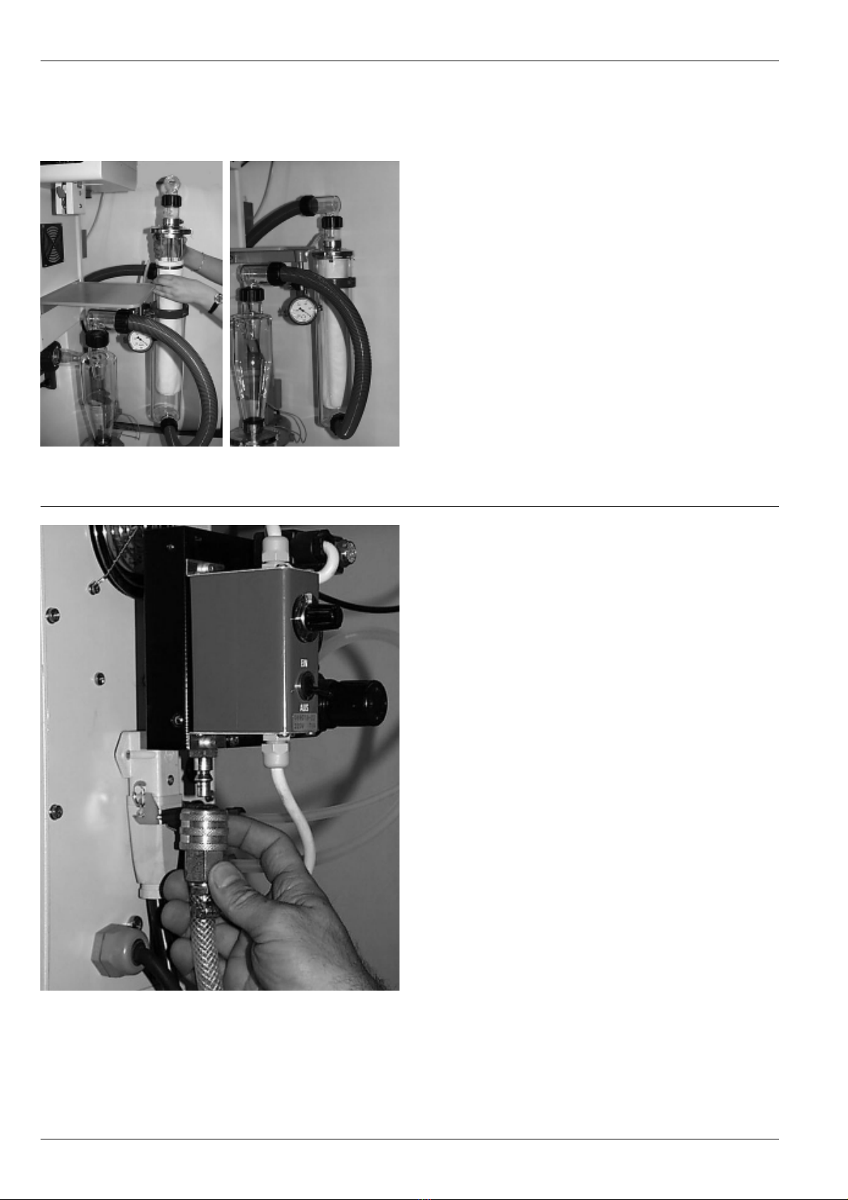
Figure 5a: Glass assembly
4.3 Installation of glass parts
Care is to be taken that only glassware in perfect condition is
used, which shows no cracks, stars or other damage. The
glassware is to be checked visually before the initial putting
into operation of the apparatus.
The glass parts are already mounted on the apparatus in the
packaging.
1. The spray cylinder 햲is held in position by means of the
sprung clamping device 햳.
2. Care is always to be taken that the rubber gasket 햴is fit-
ted correctly during the installation of the cylinder.
3. The temperature probe PT-100 햵must be inserted in the
opening provided in the coupling 햶.
4. The support 햷must be pushed upwards in such a way
that the complete spray cylinder rests on top. The screw
joint for fixing the support in position should be lightly tighten-
ed by hand.
5. The separator 햸is bolted down to the bottom end of the
spray cylinder with an SVL 42 screw cap.
6. The cyclone must be screwed onto the coupling with a
flange screw joint.
7. The glass elbow, which is attached manually, is located
on the cyclone.
8. The product receiving vessel is fastened on the bottom
end of the cyclone. The anchor clamps provided are suffi-
cient as mounting.
9. The earthing cable must be installed in the socket connector
provided on the cover of the product receiving vessel and
connected to the housing.
10. When assembling the coupling part, the teflon piece 햹is
inserted with the rectangular shoulder and the fitted contact
ring 햺first. The slanting shoulder is connected to the spray
cylinder. The centering bolt is supplied in order to fit the
flanged nut tight.
4.4 Installation of the product feed hose
1. In or to be able to install the product feed hose, the rollers
of the hose compression pump (peristalsis pump) must be
raised from the working surface. This is possible by opening
the holding device with the tilting lever.
2. The product feed hose (silicon hose 4x2 mm) is now pulled
through the holder until the nipple integrated in the hose is
at the opening.
3. The hose is now laid between the rollers and the working
surface without tautening.
4. The working area is pressed to the rollers by lifting the
orange tilting lever.
5. The observation window must now be installed in front of
the pump for the safety of the operator.
6. The pump bed (working area) should be lowered by opera-
tional interruption and stoppages in order to protect the
hose.
Figure 6: Product feed hose and peristalsis pump
햲
햳
햴
햵
햶
햷
햸
햶
햹햺
Figure 5b: Coupling part, complete

9
BÜCHI Mini Spray Dryer B-191 4 Putting into operation
Figure 7: Nozzle and product feed hose
Figure 8: Intake filter
4.5 Installation of the spray nozzle
1. Insert the spray nozzle 햲in the opening provided in the
heating oven and connect product feed hose 햳.
2. Then close housing cover 햴in order to continue further
installation.
3. Screw the compressed air tube 햵on the nozzle.
4. In order to reduce warming of the product in the nozzle,
cooling water (tube diameter 5 x 3 mm) can be connected
to the nozzle. Care must be given that the cooling water
inlet is labeled with “E” and the outlet with “A”. Only when
connected in this manner can optimal cooling of the prod-
uct be guaranteed.
4.6 Installation of the intake filter
The intake filter consists of a tube 햲, a housing 햳and a filter
element 햴which filters fine dust particles from the aspirated
air and thus prevents a contamination of the sprayed product
with particles from the air. The flexible connecting tube makes
possible an optimal placement of the filter and is connected
to the air suction supports 햵of the B-191. The tube can be
secured with the supplied clamp.
햲
햳
햵
햴
햲
햳
햴
햵

10
4 Putting into operation BÜCHI Mini Spray Dryer B-191
Figure 9: Aspirator filter
Figure 10: Compressed air line
4.7 Installation of the aspirator filter
The aspirator filter, consisting of a woven polyester fabric (type
911-400), prevents dustiness and the possible blocking of the
aspirator by very fine particles which can not be separated in
the cyclone. In the case of extreme soiling of the filter sack,
this can be washed by hand or machine. The filter is delivered
with all connections.
Care is to be taken by installation that the air which is to be
cleaned flows through the filter sack from the outside to the
inside. The manometer is thus attached to the aspirator side
of the filter sack and shows the negative pressure which comes
about on account of the soiling of the filter by fine particles.
The easy installation allows retrofitting on every apparatus.
4.8 Installation of the compressed air
Compressed air is necessary for the spray process, so that
an even spray cone of the product can be achieved in the
spray cylinder. For this purpose, 5-8 bar pressure should be
available.
If the apparatus be supplied with pneumatic nozzle cleaner,
this changes installation in so far as the air must pass through
the control unit of the nozzle cleaner before entering the appa-
ratus.

11
BÜCHI Mini Spray Dryer B-191 4 Putting into operation
Figure 11: Automatic nozzle cleaner
4.9 Installation of the automatic nozzle cleaner
For products which tend to clog the nozzle during the spray
process, the cleaning of the nozzle can be automated.
1. Install the complete control unit with the angle piece on
the rear panel as illustrated. The short screws are for
mounting the angle piece on the housing and the some-
what longer screws are for mounting the control unit on
the angle piece. The compressed air hose must first be
removed if the control unit is being retrofitted.
2. Screw the supplied double nipple into the apparatus-side
compressed air connection.
3. Install the connecting hose 쎻between the control unit
and the installed double nipple 쎻.
4. Connect the control unit with the attached power supply
cable to the receptacle on the back of the apparatus.
5. Now connect the black connecting hose to the nozzle on
the control unit as illustrated. Loosen the screw cap and
then retighten to fix the hose in position.
6. Connect the central compressed air hose 쎻with the con-
trol unit.
7. Open compressed air cock (5-8 bar).
8. Now set the nozzle pressure to 4.5 bar. The turning knob
can be turned by lightly pulling out and the nozzle pressure
of 4.5 bar can be set. Do not reduce pressure on the cen-
tral pressure connection since the apparatus requires 5-8
bar air pressure for normal operation.
9. Turn control unit on. The action interval of the cleaning
needle from 1-10 seconds can now be selected by hand
with the rotary switch. For products which clog the nozzle
very quickly the interval must be kept very small.

12
4 Putting into operation BÜCHI Mini Spray Dryer B-191
Figure 12: Pneumatic action cylinder
4.10 Installation of the pneumatic action cylinder
on the nozzle
1. Unscrew the push-button 쎻for manual nozzle cleaning
from the nozzle.
2. Screw the adapter 쎻with the damping ring 쎻on the
needle shaft 쎻and tighten well.
3. Care is to be taken before mounting the jaw that the hex-
socket screw which is there as an aid to disassembly is
loosened. Now insert the jaw 쎻until it stops on the spring
guide.
4. The position of the compressed air hose should lie between
the two cooling water hoses.
5. There should be no space between the adapter and the
action cylinder.
6. The jaw is to be tightened after it successfully inserted.
7. The cylinder screw 쎻with hex-socket head provided for
expansion in disassembly of the jaw 쎻must be removed
when tightening the screw. This screw is only used for dis-
assembly (expansion of the jaw) of the adapter.
4.11 Installation check
An installation check is to take place after successful installation
and before the first spray drying:
• Inspect the glass visually for possible damage.
• Check the electrical connections.
• The cover of the receiving vessel must be connected with
the apparatus by means of the cable for arresting electro-
static charges.
• The outlet temperature probe must be inserted in the
coupling.
• The apparatus is to be connected to the power supply
and operated only after these checks.

13
BÜCHI Mini Spray Dryer B-191 5 Operation
5 Operation
Figure 14: Operating and display elements on
the pneumatic nozzle cleaner
Make sure that the apparatus has been put into operation in
accordance with Chapter 4, Putting into operation.
5.1 Layout of the operating and display elements
햲Main switch
햳Rotary switch for selection of air flow
햴Inspection glass for air quantity
햵Main switch, pump
햶Main switch, aspirator
햷Main switch, heating
햸Main switch, pneumatic nozzle cleaner
햹Main switch, magnetic stirrer
햺Regulating push-button, pump
햻Regulating push-button, aspirator
햽Regulating push-button, heating
햾Air flow regulation, “Sprayflow”
햿Pressure selection adjustment, nozzle cleaner
헀Nozzle cleaner interval adjustment
헁LED display pump output in %
헂LED display aspirator output in %
헃LED display index values, input air temperature
헄LED display actual value, input air temperature
헅LED display actual value, output air temperature
헆Flow meter for air flow rate in the nozzle (spray flow)
쎻Manometer, nozzle cleaning pressure
쎻Manometer filter, aspirator output (only for aspirator filter)
21
22
헁
헄
헂
햿
헀
헃
햵
햶
햷
햲
햳
햴
햻
햹
햺
햾
햸
Figure 13: Operating and display elements

14
5 Operation BÜCHI Mini Spray Dryer B-191
5.2 Spray process
1. Turn apparatus on using the main switch and open the
main compressed-air cock. The apparatus now carries
out an automatic self check and then goes automatically
into operating mode.
2. If the apparatus is provided with pneumatic nozzle cleaner
than the pressure in the manometer of the control unit
must display 4.5 bar. If this is not the case this must be
readjusted with the adjustment knob on the control unit.
3. Set air flow at about 600 l/h with the adjustment knob.
4. Preselect the desired input temperature with the adjust-
ment button.
5. Turn on the aspirator and set output with the adjustment
button. This output selection is an empirical value which
differs from product to product and can not be given.
6. Turn on heating and allow the system to warm-up. The
system regulates the input temperature itself. The LED in
the heating adjustment button only goes out when the
system temperature has stabilized. The LED is not a heat-
ing interval display.
7. If necessary, the nozzle cooling water and, if present, the
nozzle cleaner, are now turned on.
8. Distilled water is now slowly sprayed in by means of the
peristalsis pump. The spray cone now produced should
be located in the middle of the spray cylinder. If this is not
the case the nozzle may be dirty or defective.
9. The spray quantity of distilled water can be changed with
the adjustment button of the peristalsis pump. The spray
quantity in turn has an influence on the output temperature,
since the water draws energy from the air by evaporation.
In this way the output temperature can be set to the desired
value with the quantity of sprayed water and pump speed
of the peristalsis pump. Care is to be taken that the product
is not destroyed by a too high output temperature.
10. As soon as the desired operating conditions have been
achieved and are stable, the distilled water which is sprayed
in is replaced by the prepared product. Somewhat less
water is now sprayed into the system by the concentration
of the product in the water, which results in renewed ad-
justment of the output temperature (the pump output can
be slightly increased).

15
BÜCHI Mini Spray Dryer B-191 5 Operation
11. The spray process should now be constantly monitor-
ed. In addition to constant temperatures, care should be
taken that the nozzle does not become clogged. If this
should happen, the nozzle must be cleaned immediately,
either manually or by increasing the cleaning interval of
the pneumatic nozzle cleaner. A clogged nozzle can lead
to the product feed hose bursting.
12. Product deposits on the glass parts can possibly be remov-
ed with light tapping.
Any change to the system and/or the spray parameters (in-
crease in nozzle cleaning interval, change of air flow, etc.), no
matter how minor, can lead to a change in the physical pro-
perties of the product (dry content, particle size, etc.).
5.3 End of spray process
1. Distilled water should continue to be sprayed for a short
time at the end of the spray process, in order to remove
product deposits from the hoses and the nozzle.
2. Pump the hoses empty, turn off the peristalsis pump and
lower pump bed.
3. Turn off nozzle cleaner.
4. Turn off heating.
5. The system now cools down to the surrounding tempera-
ture by itself.
6. As soon as the temperature in the apparatus sinks below
70°C, the aspirator can be turned off.
7. The receiving vessel with the product can now be removed.
This should not be done when the aspirator is on since
there is the possibility that the air stream could blow the
product out of the receiving vessel into the surrounding
area.
8. The glass assembly, hoses and the nozzle should be clean-
ed with water after every spray process.

16
5 Operation BÜCHI Mini Spray Dryer B-191
5.4 Fault elimination
Fault Possible cause Elimination
Not possible to switch on No power Plug in apparatus /
check plug for damage
Fuse “burned out” Change fuse (3.15 AT)
Peristalsis pump does not feed Rollers not touching working area Raise working area with lever
Set elevation height of working area
from below with hex-socket screw
Aspirator loud Soiling of aspirator Clean the aspirator
If no aspirator filter is fitted, one should
be installed in order to reduce further
contamination of the filter
System does not heat Heating not switched on Switch on heating
Intake index value is lower than Preselect intake temperature again
room temperature
Fuse Change fuse (12.5 AT)
Heating defective Contact customer service
Nozzle clogged Product too concentrated Pump lower concentration
Increase nozzle cleaning interval
Encrustment on nozzle outlet Cool nozzle with cooling water
opening
Product drips in spray cylinder No spray flow Open compressed-air cock
Too little spray flow Increase spray flow
Check air pressure in line (5-8 bar)
Insufficient aspirator output Aspirator filter clogged Remove and clean filter
Deposits on spray cylinder Nozzle not clean Completely disassemble nozzle and
clean with water
Nozzle defective (bent) Replace nozzle
Product does not dry Reduce temperature difference
between intake and output
Increase air flow (600 l/h)
Reduce peristalsis pump output
Input temperature over the Sink intake temperature
melting point of product
Deposits in cyclone Partially product-based No possibility for elimination
Static charge Plug in earthing cable
Product too moist Increase output temperature in order
to keep the product drier
Turn down aspirator output in order
to extend the product dwell time

17
BÜCHI Mini Spray Dryer B-191 5 Operation
Fault Possible cause Elimination
Output temperature does not Probe not inserted Insert probe in coupling
increase
Decrease in input temperature Heating off Switch heating on
Fuse burned out Change fuse (12.5 AT)
Decrease in output temperature Heating off Switch heating on
Spraying too quickly Reduce feed output of peristalsis
pump
Peristalsis pump lever open Close lever
Increase in output temperature Nozzle clogged Clean nozzle by pressing the cleaning
button or by switching on the nozzle
cleaner
Increase nozzle cleaning interval
Reduce product concentration
Product hose defective Replace product feed hose
Hose not immersed in solution Immerse hose
Change of concentration in Stir product solution (magnetic stirrer)
solution in order to get an even concentration
No product feed Switch on peristalsis pump
Fault code display 000 Input temperature probe defective Contact customer service
Fault code display 001 Output temperature probe Contact customer service
defective
Fault code display 002 Temperature linearity defective Contact customer service
Fault code display 003 Aspirator tachometer defective Contact customer service
Table 3: Fault elimination
Customer service
The addresses of the official Büchi customer service centers
are on the last jacket page of these operating instructions.
Please contact these centers in case of faults, technical que-
ries and use problems.

18
6 Maintenance BÜCHI Mini Spray Dryer B-191
6 Maintenance
Follow all instructions aimed at keeping the Mini Spray Dryer
in a reliable operational state. This includes periodic cleaning
and inspection for noticeable damage.
Check that the plug has been pulled out and that the com-
pressed air and cooling water are both switched off before
maintenance work on the apparatus.
6.1 Cleaning
The glassware is to be cleaned with the usual cleaning agents
(e.g. mild soap solution).
The housing is to be cleaned with a damp cloth without the
use of organic solvents and to be visually inspected for defects
(operating elements, plug). Defective apparatus components
are to be replaced.
6.2 Customer service
Repairs to the apparatus may only be carried out by authorized
service technicians. These are persons with a sound technical
training and knowledge of the dangers which result from not
observing safety regulations.
Authorized Büchi service centers have a special service manu-
al available to them.

19
BÜCHI Mini Spray Dryer B-191 6 Maintenance
Figure 15: Block diagram
6.3 Block diagram
Only the specified parts of the Mini Spray Dryer meant for
functional performance may be installed and removed.
This is possible manually or with the supplied tools. The
removal of protective fixtures and covers with the aid of
the usual tools is forbidden, except by authorized repair
and maintenance personnel.
If the Mini Spray Dryer must be moved, take care that the
plug is pulled, the compressed-air hose is no longer under
pressure and is uncoupled from the apparatus. In addition,
the glass assembly must be cooled off.

20
7 Taking out of operation BÜCHI Mini Spray Dryer B-191
7 Taking out of operation
Dangerous substances must be removed and the apparatus
must be thoroughly cleaned. In this way any risk that persons
will be injured through contact with dangerous substances
will be eliminated.
7.1 Storage
The apparatus and accessories must be stored in a dry loca-
tion.
7.2 Packing/transport
The original packaging is designed for the transportation of
the apparatus as well as the glass parts. Only the original
packaging is to be used for any possible further transport.
7.3 Disposal
So that the Mini Spray Dryer can be disposed of in an environ-
mentally-correct manner, there is a list of the materials of the
most important parts, which are also provided with material
codes, in Chapter 9, Appendix. This guarantees that the parts
can be separated and recycled. We refer you to the corre-
sponding guidelines for the disposal of electrical parts. In addi-
tion, regional and local laws are to be observed by disposal.
Table of contents
Other Buchi Dryer manuals