Buchi V-100 User manual

Vacuum Pump V-100
Operation Manual
11593636E en

Imprint
Product Identification:
Operation Manual (Original) Vacuum Pump V-100
11593636
Publication date: 06.2017
BÜCHI Labortechnik AG
Meierseggstrasse 40
Postfach
CH-9230 Flawil 1
E-Mail: [email protected]
BUCHI reserves the right to make changes to the manual as deemed necessary in the light of experi-
ence, especially with respect to structure, illustrations and technical detail.
This manual is copyrighted. Information from it may not be reproduced, distributed, or used for competi-
tive purposes, nor made available to third parties. The manufacture of any component with the aid of this
manual without prior written agreement is also prohibited.

BÜCHI Labortechnik AG Contents
Operation Manual Vacuum Pump V-100 iii
Contents
1 About this document...........................................................................................................5
1.1 Warning notices in this document........................................................................................................ 5
1.2 Symbols............................................................................................................................................... 5
1.2.1 Warning symbols .....................................................................................................................5
1.2.2 Mandatory directive symbols ...................................................................................................6
1.2.3 Other symbols..........................................................................................................................6
1.3 Available languages............................................................................................................................. 6
1.4 Trademarks.......................................................................................................................................... 6
2 Safety....................................................................................................................................7
2.1 Intended use........................................................................................................................................ 7
2.2 Use other than that intended ............................................................................................................... 7
2.3 Staff qualification ................................................................................................................................. 7
2.4 Residual risks ...................................................................................................................................... 8
2.4.1 Dangerous vapors.................................................................................................................... 8
2.4.2 Faults during operation ............................................................................................................8
2.5 Personal protective equipment ............................................................................................................ 8
2.6 Modifications........................................................................................................................................ 8
3 Product description...........................................................................................................10
3.1 Description of function ....................................................................................................................... 10
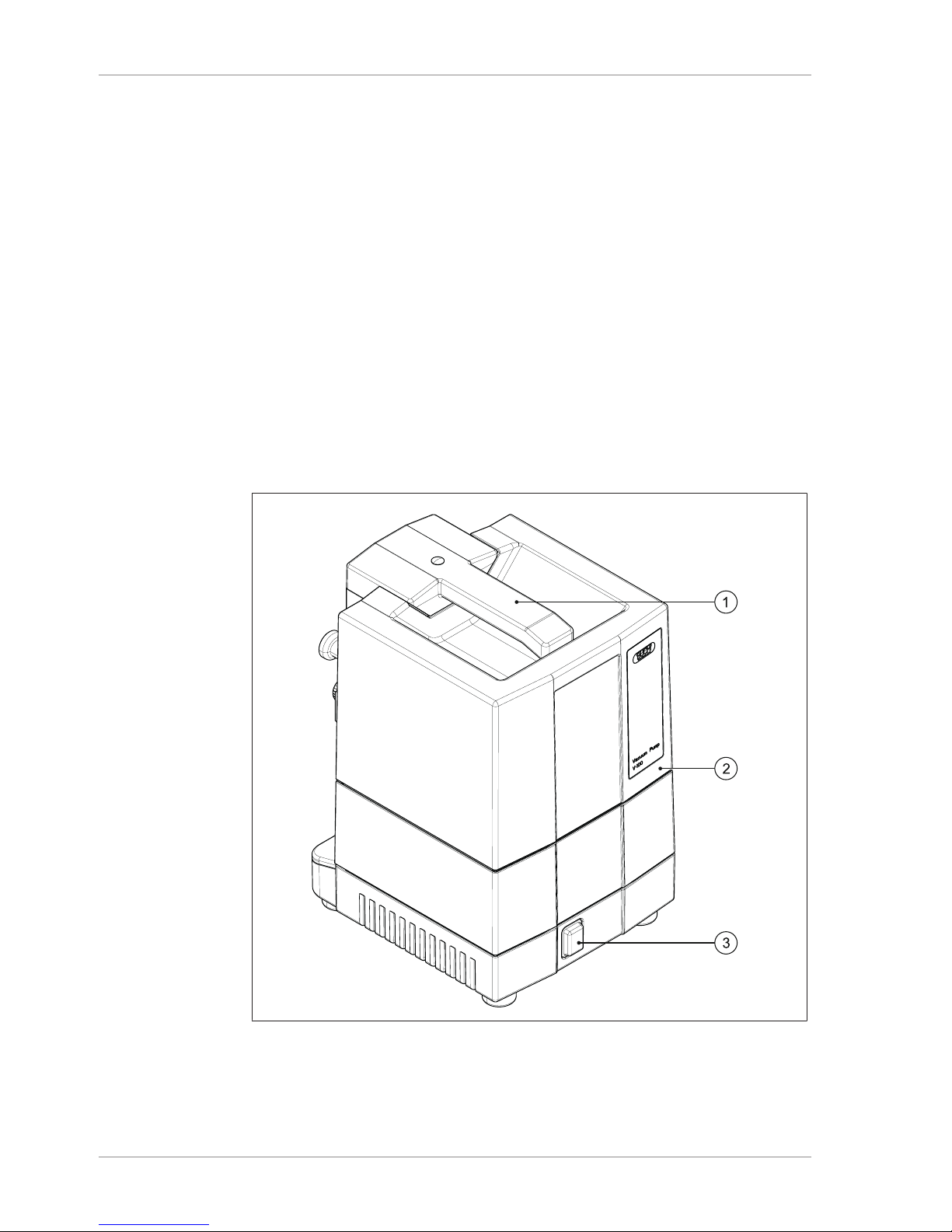
3.2 Configuration ..................................................................................................................................... 10
3.2.1 Front view ..............................................................................................................................10
3.2.2 Rear view ...............................................................................................................................11
3.2.3 Internal view...........................................................................................................................12
3.2.4 Typical application .................................................................................................................13
3.2.5 Type plate ..............................................................................................................................14
3.3 Specifications supplied ...................................................................................................................... 14
3.4 Technical data ................................................................................................................................... 15
3.4.1 Vacuum Pump V-100.............................................................................................................15
3.4.2 Ambient conditions.................................................................................................................15
3.4.3 Materials ................................................................................................................................15
4 Transport and storage ......................................................................................................16
4.1 Transport ........................................................................................................................................... 16
4.2 Storage .............................................................................................................................................. 16
4.3 Removing transit fixings..................................................................................................................... 17
5 Installation..........................................................................................................................18
5.1 Important considerations prior to commissioning .............................................................................. 18
5.2 Installation site................................................................................................................................... 19
5.3 Connecting laboratory equipment...................................................................................................... 19
5.4 Connecting the silencer ..................................................................................................................... 21
5.5 Connecting a Woulff bottle................................................................................................................. 23
5.6 Connecting a secondary condenser .................................................................................................. 24
5.7 Connecting a secondary cooling cold trap......................................................................................... 26
5.8 Electrical connections........................................................................................................................ 27
5.9 Fitting and connecting the Interface I-100 ......................................................................................... 28
5.9.1 Fitting an interface unit to the Vacuum Pump V-100 .............................................................28
5.9.2 Connecting interface unit to Vacuum Pump V-100................................................................ 29

Contents BÜCHI Labortechnik AG
iv Operation Manual Vacuum Pump V-100
6 Operation............................................................................................................................30
6.1 Operating V-100 with Interface I-100................................................................................................. 30
6.2 Operating V-100 without Interface I-100............................................................................................ 30
7 Cleaning and servicing .....................................................................................................31
7.1 Cleaning............................................................................................................................................. 31
7.1.1 Important considerations when cleaning................................................................................ 31
7.1.2 Cleaning the pump.................................................................................................................31
7.1.3 After working with strong acids ..............................................................................................31
7.1.4 Cleaning the housing .............................................................................................................32
7.1.5 Cleaning glass components...................................................................................................32
7.1.6 Cleaning tubing...................................................................................................................... 32
7.1.7 Cleaning valve heads.............................................................................................................32
7.1.8 Cleaning non-return valve......................................................................................................33
7.1.9 Cleaning the membrane......................................................................................................... 33
7.2 Servicing............................................................................................................................................ 33
7.2.1 Notes on servicing .................................................................................................................33
7.2.2 Dismantling and reassembling pump head............................................................................35
7.2.3 Replacing the membrane.......................................................................................................38
7.2.4 Replacing valve......................................................................................................................39
7.2.5 Replacing tubing ....................................................................................................................40
8 Help with faults ..................................................................................................................41
8.1 Faults, possible causes and remedies............................................................................................... 41
8.2 Customer service............................................................................................................................... 42
9 Taking out of service and disposal..................................................................................43
9.1 Taking out of service.......................................................................................................................... 43
9.2 Disposal............................................................................................................................................. 43
10 Appendix ............................................................................................................................44
10.1 Solvent table...................................................................................................................................... 44
10.2 Spare parts and accessories ............................................................................................................. 46
10.2.1 Accessories............................................................................................................................46
10.2.2 Wear parts .............................................................................................................................47
10.2.3 Spare parts ............................................................................................................................48
10.3 List of abbreviations........................................................................................................................... 49
10.4 Health and safety approval................................................................................................................ 49
10.5 Health and safety............................................................................................................................... 50

BÜCHI Labortechnik AG About this document | 1
Operation Manual Vacuum Pump V-100 5/52
1 About this document
These operating instructions describe the Vacuum Pump V-100 at the time supplied.
They are an integral part of the product and contain important information that is nec-
essary for safe operation and maintenance.
These operating instructions apply to all variants of the Vacuum Pump V-100 and are
intended primarily for laboratory staff.
uTo ensure safe and trouble-free operation, read these operating instructions be-
fore starting up the device and follow the guidance they contain.
uKeep the operating instructions somewhere near to the device.
uPass on the operating instructions to any subsequent owner or user.
BÜCHI Labortechnik AG accepts no liability whatsoever for any faults or damage that
result from the failure to follow these operating instructions.
uIf you still have any questions after reading these operating instructions, please
contact BÜCHI Labortechnik AG Customer Service. Contact details for your local
agents can be found on the back cover of these operating instructions or on the In-
ternet at http://www.buchi.com.
1.1 Warning notices in this document
Warning notices warn you of dangers that can occur when handling the device. There
are four danger levels, each identifiable by the signal word used.
Signal word Meaning
DANGER Indicates a danger with a high level of risk which could result in
death or serious injury if not prevented.
WARNING Indicates a danger with a medium level of risk which could result in
death or serious injury if not prevented.
CAUTION Indicates a danger with a low level of risk which could result in mi-
nor or medium-severity injury if not prevented.
IMPORTANT Indicates a danger that could result in damage to property.
1.2 Symbols
The following symbols may be displayed in this instruction manual or on the device:
1.2.1 Warning symbols
Symbol Meaning Symbol Meaning
General warning Corrosive substance
Dangerous electrical voltage Flammable substance
Biological hazard Potentially explosive atmos-
phere
Breakable items Dangerous gases

1 | About this document BÜCHI Labortechnik AG
6/52 Operation Manual Vacuum Pump V-100
Symbol Meaning Symbol Meaning
Hot surface Health-harming or irritant
substances
Risk of hand injury Strong magnetism
1.2.2 Mandatory directive symbols
Symbol Meaning Symbol Meaning
Wear safety goggles Wear protective clothing
Wear protective gloves Heavy load, do not lift with-
out assistance
1.2.3 Other symbols
NOTE
This symbol draws attention to useful and important information.
RThis character draws attention to a requirement that must be met before the in-
structions below are carried out.
uThis character indicates an instruction that must be carried out by the user.
5This character indicates the result of a correctly carried out instruction.
1.3 Available languages
These operating instructions were originally produced in German and have been
translated into several other languages. The translations are available on the en-
closed CD or can be obtained as a PDF file via http://www.buchi.com.
1.4 Trademarks
Product names and registered or unregistered trademarks that are used in this in-
struction manual are used only for identification and remain the property of the owner
in each case.
For example, Rotavapor® is a registered trademark of BÜCHI Labortechnik AG.

BÜCHI Labortechnik AG Safety | 2
Operation Manual Vacuum Pump V-100 7/52
2 Safety
2.1 Intended use
The Vacuum Pump V-100 has been designed and built as an item of laboratory
equipment. Its intended use is the evacuation of laboratory apparatus. This is done by
means of a PTFE-membrane pump – with or without regulation by a vacuum con-
troller.
PTFE-membrane pumps are used primarily for the following applications:
Evacuating distillation apparatus, in particular rotary evaporators (Rotavapor®)
Vacuum filtration
Vacuum-drying cabinets
Drying kilns
2.2 Use other than that intended
Use of any kind other than that referred to and any application that does not comply
with the technical specifications constitutes use other than that intended. The opera-
tor alone is liable for any damage brought about by use of the device in a manner
other than that intended.
In particular, the following applications are not permissible:
Use in areas which require explosion-safe apparatus.
Pumping of liquids and solid particles.
Processing samples which could be caused to explode or ignite by impact, friction,
heat or sparks (e.g. explosives).
Use for analysis (e.g. Kjeldahl).
Generation of positive pressure (pressurizing a system).
Operation at ambient temperatures >40 °C.
2.3 Staff qualification
Unqualified persons are unable to identify risks and are therefore exposed to greater
dangers.
The device may only be operated by suitably qualified laboratory staff.
These operating instructions are aimed at the following target groups:
Users
Users are persons that meet the following criteria:
They have been instructed in the use of the device.
They are familiar with the contents of these operating instructions and the applica-
ble safety regulations and apply them.
They are able on the basis of their training or professional experience to assess
the risks associated with the use of the device.

2 | Safety BÜCHI Labortechnik AG
8/52 Operation Manual Vacuum Pump V-100
Operator
The operator (generally the laboratory manager) is responsible for the following as-
pects:
The device must be correctly installed, commissioned, operated and serviced.
Only suitably qualified staff may be assigned the task of performing the operations
described in these operating instructions.
The staff must comply with the locally applicable requirements and regulations for
safe and hazard-conscious working practices.
Safety-related incidents that occur while using the device should be reported to the
manufacturer ([email protected]).
BUCHI service technicians
Service technicians authorized by BUCHI have attended special training courses and
are authorized by BÜCHILabortechnikAG to carry out special servicing and repair
measures.
2.4 Residual risks
The device has been developed and manufactured using the latest technological ad-
vances. Nevertheless, risks to persons, property or the environment can arise if the
device is used incorrectly.
Appropriate warnings in this manual serve to alert the user to these residual dangers.
2.4.1 Dangerous vapors
Distillation can produce dangerous vapors that are capable of causing life-threatening
toxic effects.
uDo not inhale any vapors produced during distillation.
uEnsure that vapors are removed immediately by a suitable fume hood.
uOnly use the device in well ventilated areas.
uIf vapors escape from joints or connections, check the seals concerned and re-
place them if necessary.
uDo not distill any unknown fluids.
uObserve the safety data sheets for all fluids used.
2.4.2 Faults during operation
If a device is damaged, sharp edges or exposed electrical wires can cause injuries.
uRegularly check device for visible damage.
uIf faults occur, switch off the device immediately, unplug the power cord and in-
form the operator.
uDo not continue to use devices that are damaged.
2.5 Personal protective equipment
Depending on the application, hazards due to heat and/or corrosive chemicals may
arise.
uAlways wear appropriate personal protective equipment such as safety goggles,
protective clothing and gloves.
uMake sure that the personal protective equipment meets the requirements of the
safety data sheets for all chemicals used.
2.6 Modifications
Unauthorized modifications may impair safety and lead to accidents.

BÜCHI Labortechnik AG Safety | 2
Operation Manual Vacuum Pump V-100 9/52
uUse only genuine BUCHI accessories, spare parts and consumables.
uTechnical modifications to the device or accessories should only be carried out
with the prior written approval of BÜCHILabortechnikAG and only by authorized
BUCHI technicians.
BUCHI accepts no liability whatsoever for damage arising as a result of unauthorized
modifications.

3 | Product description BÜCHI Labortechnik AG
10/52 Operation Manual Vacuum Pump V-100
3 Product description
3.1 Description of function
The Vacuum Pump V-100 is intended for evacuating laboratory apparatus to a termi-
nal vacuum of 10mbar (±2mbar).
Once switched on, the V-100 runs in continuous mode unless it is connected to the
Interface I-100 unit. In unregulated continuous mode, the pump runs at a maximum
speed of 1280 rpm and generates a terminal vacuum of 10mbar (±2mbar). The time
required for evacuation depends on the size (volume) of the vessel.
After 1 hour of operation, the V-100 switches automatically to ECO mode. In ECO
mode, the V-100 runs at 70% capacity but still generates the same terminal vacuum
of 10mbar (±2mbar).
The pump can be operated either as a standalone device or combined with optional
accessories (see Chapter3.3 "Specifications supplied", page14).
3.2 Configuration
3.2.1 Front view
Fig.1: Design of V-100
1 Carrying handle
2 Pump top cover
3 On/Off master switch

BÜCHI Labortechnik AG Product description | 3
Operation Manual Vacuum Pump V-100 11/52
3.2.2 Rear view
1
1
1
21
4
1
5
1
6
1
7
1
3
1
1
Fig.2: Rear view of V-100
1 Knurled-head screws 4 Pump intake (vacuum)
2 Pump outlet 5 Mini-DIN connection
3 Type plate 6 Power supply connection
7 Lashing eye (for securing against
earthquakes)

3 | Product description BÜCHI Labortechnik AG
12/52 Operation Manual Vacuum Pump V-100
3.2.3 Internal view
3
4
5
6
7
1
2
Fig.3: Internal view of V-100 showing pump head and pump-head connection piece
1 Torx key (TX10) 3 Torx key (TX25)
2 Pump top cover 4 Pump outlet
5 Pump-head metal cover
6 GL14 cap nut
7 Pump-head connection piece

BÜCHI Labortechnik AG Product description | 3
Operation Manual Vacuum Pump V-100 13/52
3.2.4 Typical application
The V-100 is used for evacuating laboratory apparatus such as tubes, flasks and
other apparatus.
Recirculating
Chiller F-100
Fig.4: Typical application for the V-100 in a laboratory
1 Recirculating Chiller F-100
2 Rotavapor R-100
3 Vacuum Pump V-100 with Interface I-100
Evacuation changes the physical and chemical properties of materials. The V-100 is
ideally suited to connection to a Rotavapor R-100 in combination with a Recirculating
Chiller F-1xx. With that combination of apparatus controlled by a controller such as
the Interface I-100, ideal distillation configurations for all commonly used solvents can
be created.

3 | Product description BÜCHI Labortechnik AG
14/52 Operation Manual Vacuum Pump V-100
3.2.5 Type plate
The type plate is on the rear of the Vacuum Pump V-100.
BUCHI Operations India Pvt Ltd
394230 Surat / India
Type: V-100
SN: 1000000000
Volt: 100 – 240 VAC
Frequ.: 50/60 Hz
Power: 150 W
Built: 2014
Designed by BUCHI in Switzerland,
Made in India
3
7
2
1
5
4
6
8
9
1011
Fig.5: Type plate (example)
1 Company name and address 7 Year of manufacture
2 Device name 8 Country of manufacture
3 Serial number 9 Approvals
4 Input voltage 10 Symbol for "Do not dispose of as
household waste"
5 Frequency 11 Product code
6 Maximum power rating
3.3 Specifications supplied
V-100
Vacuum Pump V-100 1
Vacuum tubing (2 m) 1
Power supply cable 1
Silencer 1
Tubing connections (set) 1
Interface I-100 *
Woulff bottle *
Condensation unit *
Communication cables *
* As per order code

BÜCHI Labortechnik AG Product description | 3
Operation Manual Vacuum Pump V-100 15/52
3.4 Technical data
3.4.1 Vacuum Pump V-100
Dimensions (W x H x D) 180 x 275 x 210 mm
Weight 5.6 kg
Power supply voltage 100 – 240 V, 50/60 Hz
Power consumption 150 W
Power consumption in ECO mode 70 W
Terminal vacuum (absolute) 10 mbar (± 2 mbar)
Pump capacity 1.5 m3/h
Vacuum connection GL-14
Motor Brushless DC motor
Rotation speed 1280 rpm max.
Rotation speed in ECO mode 70% of max. capacity
Noise level 32 to 57 dBA
57 dBA: with 100% load
Overvoltage category II
Pollution degree 2
Enclosure rating IP20
Certificates CE
3.4.2 Ambient conditions
Max. altitude above sea level 2000 m
Ambient temperature 5 - 40 °C
Maximum relative humidity 80 % for temperatures up to 31 °C
decreasing linearly to 50 % at 40 °C
The Vacuum Pump V-100 may only be used in indoor areas.
3.4.3 Materials
Component Material
Pump heads PPS
Drive unit body Aluminium
Housing PBT
Membranes PTFE/rubber
Valve plate PEEK
Valve head PEEK
Pump-head connection piece FEP
Vacuum tubing Silicone/natural rubber
Non-return valve O-rings FFKM

4 | Transport and storage BÜCHI Labortechnik AG
16/52 Operation Manual Vacuum Pump V-100
4 Transport and storage
4.1 Transport
IMPORTANT
Risk of breakage due to incorrect transportation
uMake sure that all parts of the device are safely packed in such a way as to pre-
vent breakage, ideally in the original box.
uAvoid sharp movements during transit.
uAfter transportation, check the device for damage.
uDamage that has occurred in transit should be reported to the carrier.
uKeep packing for future transportation.
4.2 Storage
uMake sure that the ambient conditions are complied with (see Chapter3.4 "Tech-
nical data", page15).
uWherever possible, store the device in its original packaging.
uAfter storage, check the device, all seals and tubing for damage and replace if
necessary.

BÜCHI Labortechnik AG Transport and storage | 4
Operation Manual Vacuum Pump V-100 17/52
4.3 Removing transit fixings
Fig.6: Transit fixings on the rear of the Vacuum Pump V-100
1 Transit fixings 2 GL14 cap nuts
Before the V-100 is set up and put into service, the transit fixings (red) have to be re-
moved.
uOn the rear of the V-100, unscrew the GL14 cap nuts (2) from the pump intake
and pump outlet.
uPull off the red transit fixings (1).
uScrew the cap nuts back on.

5 | Installation BÜCHI Labortechnik AG
18/52 Operation Manual Vacuum Pump V-100
5 Installation
5.1 Important considerations prior to commissioning
WARNING
Risk of irritation of mucous membranes and poisoning from inhalation
of hazardous gases and vapors.
In the process of evacuation it is possible that hazardous substances may be pumped
out at the same time and released into the atmosphere. In addition, it is possible for
such substances to collect as condensation at leaking connections.
uOperate the pump inside a fume hood.
uDirect vapors from the pump outlet into the fume hood.
uIf necessary, wear a face mask and safety goggles.
uIf necessary, only handle pump and accessories with protective gloves.
WARNING
Risk of fire or explosion from flammable solvent vapors.
In the process of evacuation, it is possible for solvent vapors to get into the inside of
the pump and catch fire or explode due to the electric current.
uFollow the guidance notes for the solvents used.
uConnect a Woulff bottle upstream of the pump intake.
uOperate the pump inside a fume hood.
CAUTION
Health risks when handling corrosive substances.
uWhen working with strong acids or caustic solutions, always wear personal protec-
tive equipment (safety goggles, protective clothing, protective gloves).

BÜCHI Labortechnik AG Installation | 5
Operation Manual Vacuum Pump V-100 19/52
5.2 Installation site
uBefore setting up the V-100 and putting it into service, remove the transit fixings
(red) on the rear of the device (see Chapter4.3 "Removing transit fixings",
page17).
IMPORTANT
Risk of property damage from falling equipment (e.g. in an earthquake)
uSecure the Vacuum Pump against falling by means of the lashing eye on the rear
of the device (see Chapter3.2.2 "Rear view", page11).
The installation site must meet the following requirements:
Firm and level surface: at least 200 mm x 300 mm (W x D)
Height: at least 300 mm
Set up inside a fume hood or
feed the pump outlet into the fume hood
Sufficient air supply to the pump cooler
The V-100 is intended for use in laboratory environments (see Chapter3.4.2 "Ambi-
ent conditions", page15).
5.3 Connecting laboratory equipment
12
Fig.7: Vacuum Pump (V-100) with transit fixings
1 Pump outlet 2 Pump intake (vacuum)

5 | Installation BÜCHI Labortechnik AG
20/52 Operation Manual Vacuum Pump V-100
The V-100 is connected by a vacuum tubing to the laboratory apparatus to be evacu-
ated. The vacuum tubing leads via a GL14 connection from the pump intake (2) to the
outlet of the laboratory device concerned.
Precondition:
RTransit fixings have been removed (see Chapter4.3 "Removing transit fixings",
page17).
uFit tubing to pump intake (2) using the GL14 cap nut.
If vapors are to be expected during evacuation, we recommend the following:
uConnect a Woulff bottle upstream of the pump intake (see Chapter5.5 "Connect-
ing a Woulff bottle", page23).
uConnect the tubing to the Woulff bottle intake using a GL14 cap nut.
For details of connecting the V-100 to a rotary evaporator (e.g. Rotavapor® R-100)
see the relevant section of the device's operating instructions.
For more information on the use of the V-100, see Chapter3.2.4 "Typical application",
page13.
Table of contents
Other Buchi Water Pump manuals
Popular Water Pump manuals by other brands

Oase
Oase Aquamax 4.000 operating instructions

Elektro Maschinen
Elektro Maschinen WPEm 7000/50R Operating instruction

Master Pumps
Master Pumps MPC20V2INOX Original instructions

Elektra Beckum
Elektra Beckum P 3000 G operating instructions

Wilo
Wilo TOP-S Installation and maintenance instructions

Practivet
Practivet INFUSION PUMP quick start guide