10
BÜCHI Vac V-511/512/5134 Beginning Operation
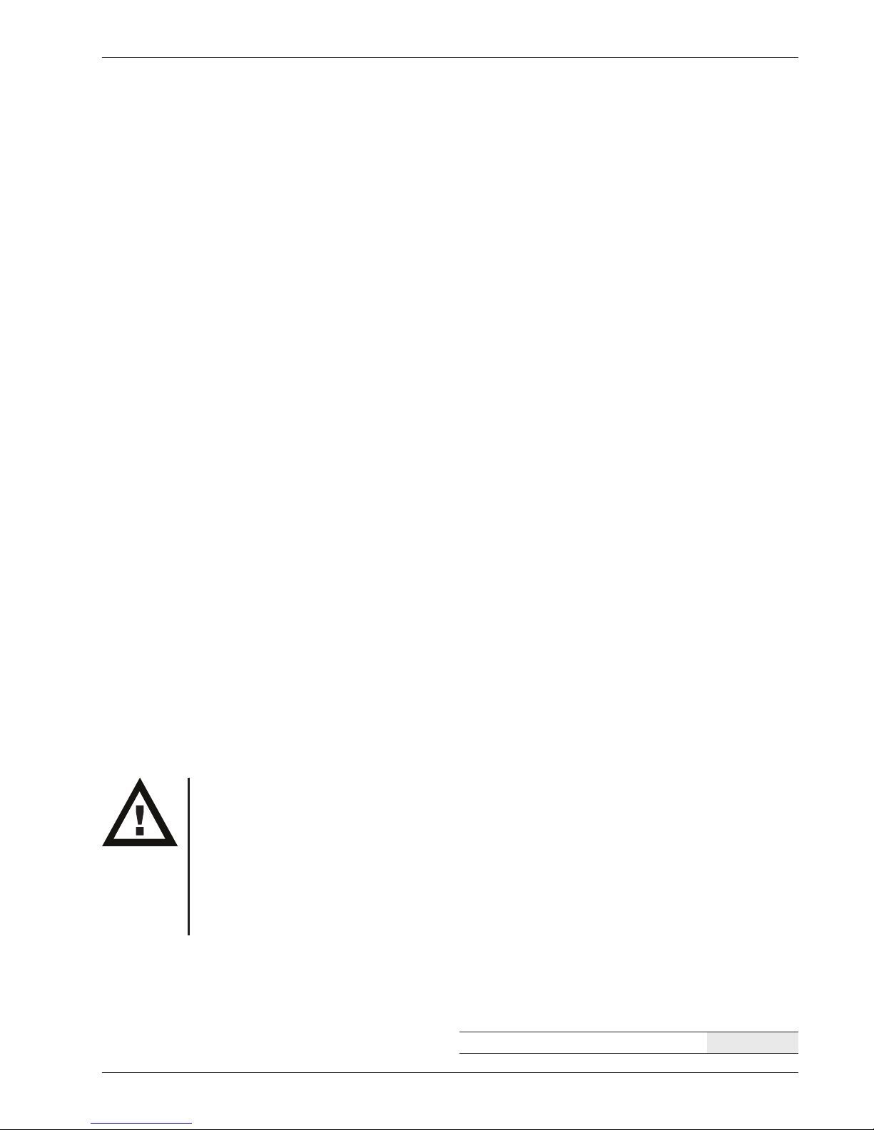
4 Beginning Operation
4.1 General
Please check all parts for damage when unpacking. It is impor-
tant that any transport damage be discovered when the parts
are unpacked. If necessary, a record of the condition of the
parts should be made immediately (report to postal service,
railway service, or shipping company).
Keep the original packaging for the event of a later transport.
4.1.1 Placement
The apparatus must be set up on a stable, clean, and level sur-
face. The surrounding temperature may not exceed 40° C.
Proper air circulation is necessary.
The apparatus must be placed at a minimum of 20 cm from
walls and other objects in order to prevent damage. Contain-
ers, chemicals, or other apparatus may not be placed behind
the pump.
4.1.2 Electrical Connections
Ensure that the electric current available from the location’s
outlets is the same voltage as that indicated by the label on
the apparatus. The apparatus must always be connected to
a grounded outlet. External couplings and extension cords
must have a protective conductor (3-pin couplings, cables, or
plug and socket connections). There must be no break in any
part of the protective conductor. This will avoid risks resulting
from internal defects.
Connect the pump to the power source with the enclosed
cable.
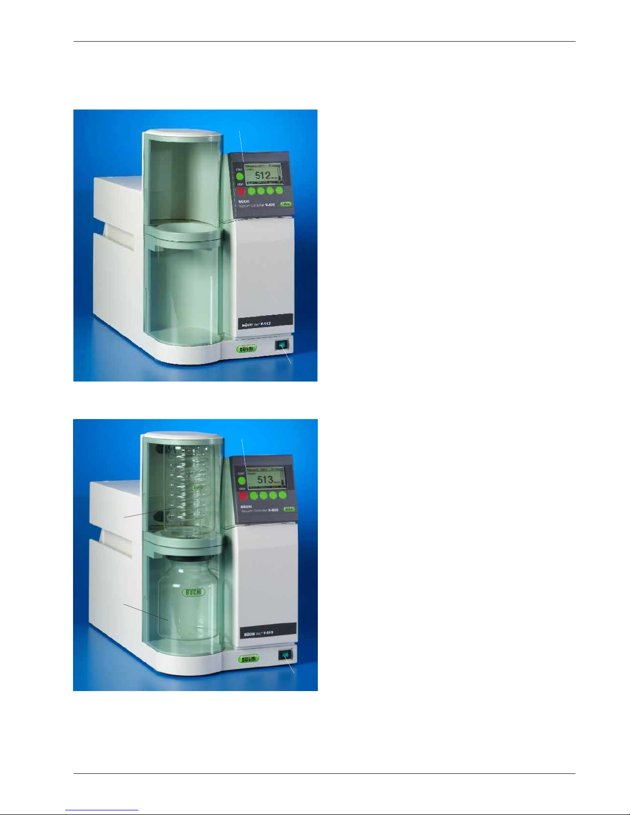
4.1.3 Hose Connections
• Please be sure that none of the hoses are bent closed
(bends, the apparatus is resting on the hose).
• Replace brittle hoses.
• The hoses should be secured with standard hose clamps
or cable binders for safety. The hoses in the apparatus it-
self have already been secured by the factory.
• The apparatus must never be put into operation without
an exhaust hose. The exhaust hose must not be pointed
towards hot objects or towards objects which produce
sparks. The exhaust hose must end in a fume hood so
that none of the vapors from the solvents can be released
in the room.