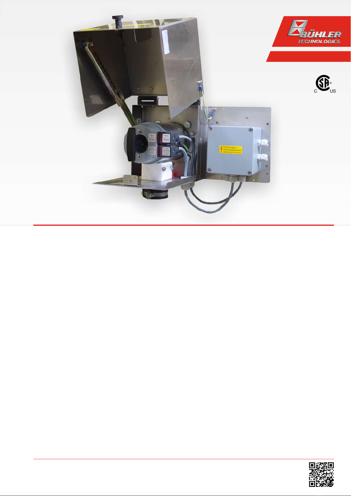
GAS 222.35 AMEX
Table of Contents
1 Introduction..................................................................................................................................................................................................................... 2
1.1 Intended Use.........................................................................................................................................................................................................2
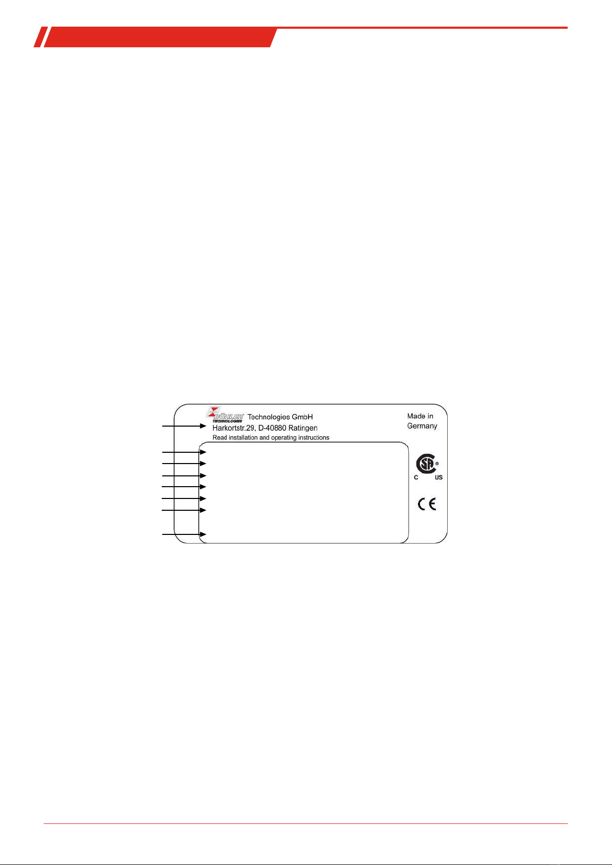
1.2 Type Plate............................................................................................................................................................................................................... 2
1.3 Scope of Delivery..................................................................................................................................................................................................2
1.4 Ordering instructions ........................................................................................................................................................................................ 3
1.5 Product Description............................................................................................................................................................................................ 3
2 Safety instructions.........................................................................................................................................................................................................4
2.1 Important advice .................................................................................................................................................................................................4
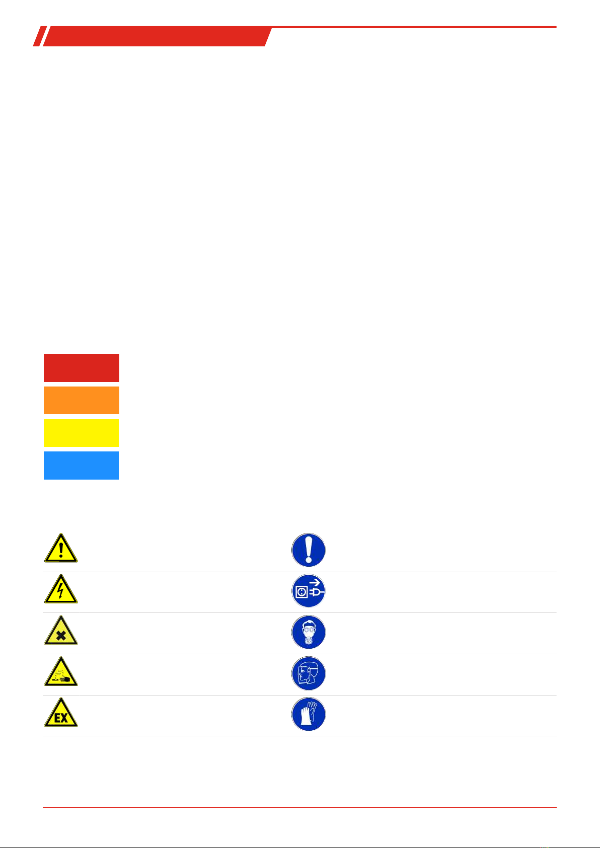
2.2 General Hazard Warnings ................................................................................................................................................................................ 5
3 Transport and storage .................................................................................................................................................................................................. 7
4 Installation and connection ........................................................................................................................................................................................8
4.1 Installation site requirements.........................................................................................................................................................................8
4.2 Installation ............................................................................................................................................................................................................8
4.3 Installing the Inlet Filter ....................................................................................................................................................................................8
4.4 Insulation...............................................................................................................................................................................................................8
4.5 Connecting the Gas Line....................................................................................................................................................................................9
4.5.1 Blowback Connection......................................................................................................................................................................... 9
4.5.2 Connecting the Gas Line.................................................................................................................................................................... 9
4.5.3 Connecting the calibrating gas line (optional)..........................................................................................................................10
4.6 Connecting the Blowback and Pressure Vessel (Optional) ...................................................................................................................10
4.7 Electrical connections ......................................................................................................................................................................................10
4.7.1 Heated pressure vessel (optional) ..................................................................................................................................................11
5 Operation and Control.................................................................................................................................................................................................13
5.1 Before Start-Up ...................................................................................................................................................................................................13
6 Maintenance.................................................................................................................................................................................................................. 14
6.1 Maintaining the filter element ......................................................................................................................................................................15
6.1.1 Replacing the Inlet Filter .................................................................................................................................................................. 15
6.2 Blowback of the in-situ filter (within the process stream).................................................................................................................... 16
6.2.1 Manual Blowback (Without Blowback Control) ........................................................................................................................16
6.2.2 Automatic Blowback (External Blowback Control)...................................................................................................................16
6.3 Maintenance Schedule .....................................................................................................................................................................................17
7 Service and repair......................................................................................................................................................................................................... 18
7.1 Troubleshooting ................................................................................................................................................................................................ 18
7.2 Spare Parts and Accessories ........................................................................................................................................................................... 19
8 Disposal...........................................................................................................................................................................................................................20
9 Appendices......................................................................................................................................................................................................................21
9.1 Technical Data.................................................................................................................................................................................................... 21
9.2 Connection Diagram ........................................................................................................................................................................................ 21
9.3 Connection diagram heated pressure vessel............................................................................................................................................22
9.4 Flow diagram......................................................................................................................................................................................................22
9.5 Dimensions .........................................................................................................................................................................................................23
9.6 List of chemical resistance..............................................................................................................................................................................24
9.7 User book (Please make copies) .................................................................................................................................................................... 25
10 Attached Documents...................................................................................................................................................................................................26
iBühler Technologies GmbHBE460058 ◦ 08/2019