Buhnen HB 11 Quick guide

Translation of the Original Operating Instructions
Micro-Application Head
HB 11
FCH0479.2XM (Issue 11/2019)
FCH0479-2XM_EN_191107.indd 1 07.11.19 14:03

2
1 Safety instructions ............................................................................................................................................3
1.1 Possible dangers............................................................................................................................................3
1.2 Notes on safe operation ................................................................................................................................3
2 General ...............................................................................................................................................................4
2.1 Operative range .............................................................................................................................................4
2.2 Technical data ................................................................................................................................................4
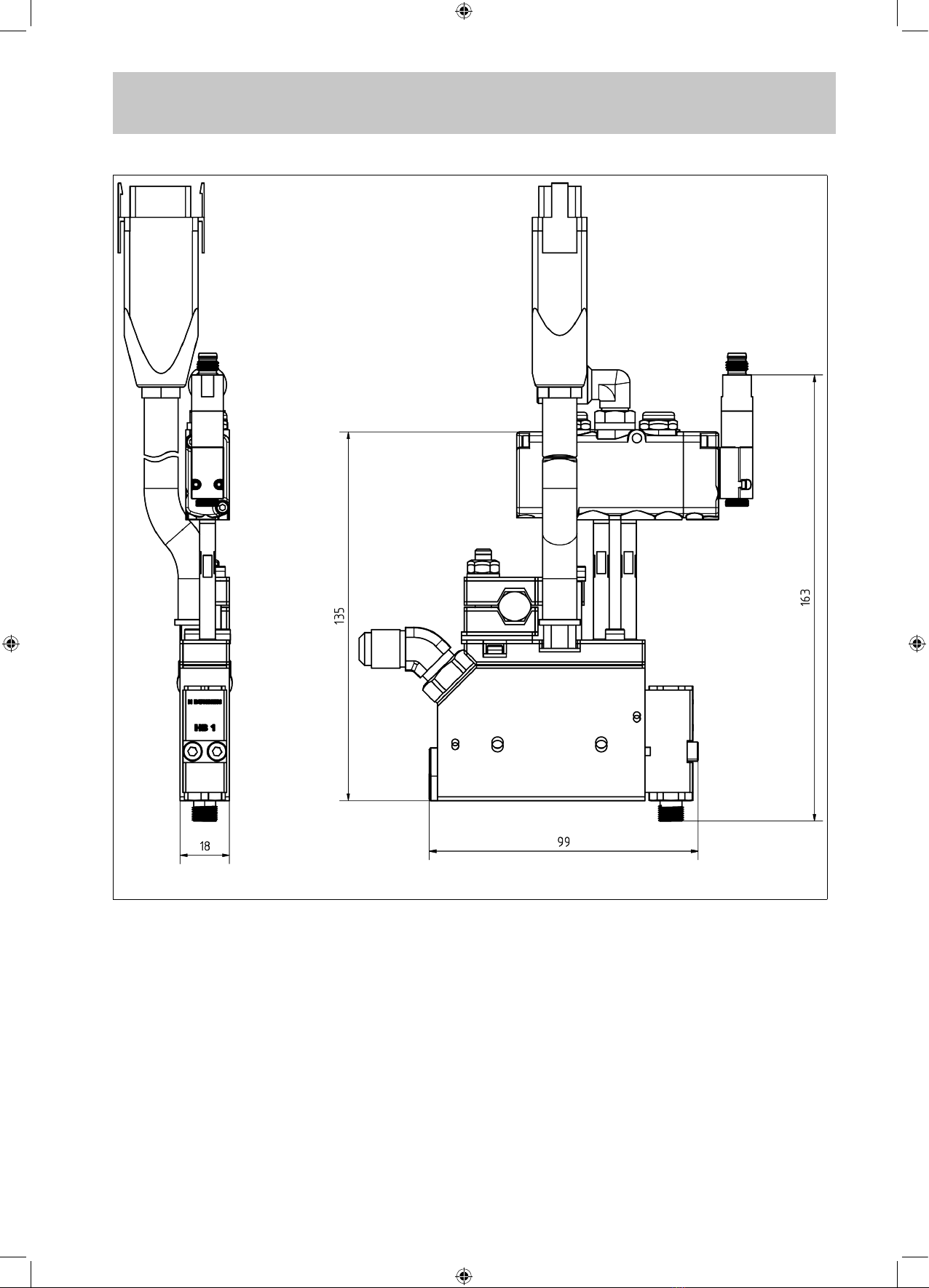
2.3 Dimensioned drawing.....................................................................................................................................5
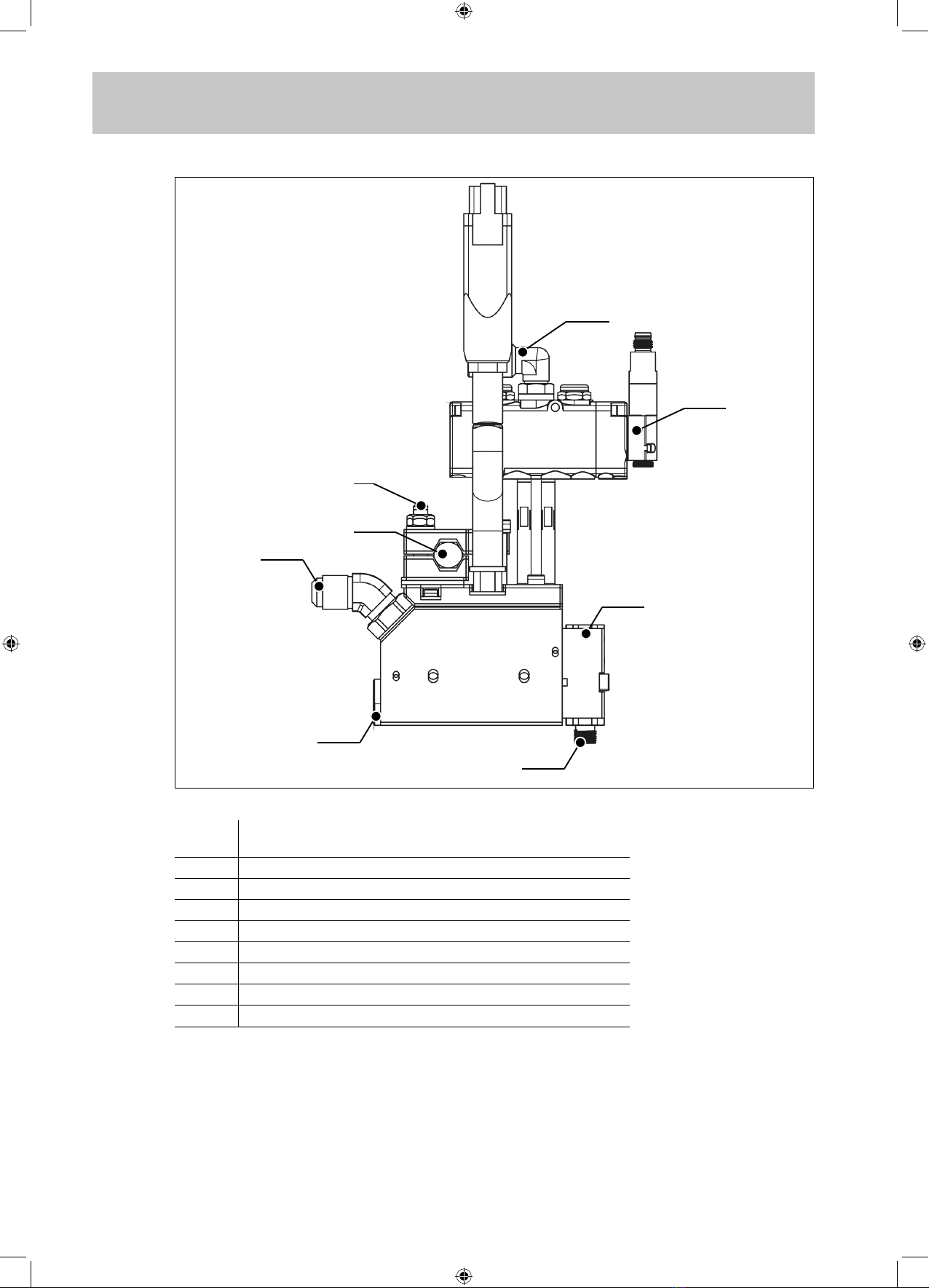
3 Assembly............................................................................................................................................................6
3.1 Electrical connection ......................................................................................................................................7
3.2 Compressed air connection ...........................................................................................................................8
3.3 Heatable hose................................................................................................................................................8
4 Operation............................................................................................................................................................8
4.1 Initial operation...............................................................................................................................................8
4.2 Adjusting the adhesive dosage ......................................................................................................................8
4.3 Interruptions in work/End of shift....................................................................................................................8
4.4 Processing PU hot melt adhesives ................................................................................................................8
5 What happens if… .............................................................................................................................................9
5.1 Troubleshooting and repair ............................................................................................................................9
6 Maintenance/servicing ....................................................................................................................................10
6.1 Maintenance intervals ..................................................................................................................................10
6.2 Cleaning.......................................................................................................................................................10
6.2.1 Clean nozzle ...............................................................................................................................................................10
6.3 Replace module HB 1 .................................................................................................................................. 11
7 Repairs..............................................................................................................................................................12
8 Warranty ...........................................................................................................................................................12
9 Disposal............................................................................................................................................................12
10 Spare parts .......................................................................................................................................................13
Declaration of Conformity...............................................................................................................................14
FCH0479-2XM_EN_191107.indd 2 07.11.19 14:03

Safety instructions
3
1 Safety instructions
1.1 Possible dangers
Danger!
Never point the operational device at other persons.
Danger due to high pressure!
Danger of burns!
The nozzle and melted hot melt adhesive can reach temperatures over 200°C. Wear heat
protection gloves whenever contact is unavoidable.
Danger due to vapours!
PU hot melt adhesives give off harmful vapours (isocyanates) even when applied in
accordance with instructions. If the prescribed processing temperature is exceeded for a
longer period, harmful decomposition products will develop.
For your safety, please observe the following notes:
• Make sure there is sufcient ventilation (S statement 51).
• Do not inhale vapours and atomised sprays (S statement 23).
• Do not smoke, eat or drink during work (S statement 20/21).
Measures for First Aid
After skin contact: Cool the affected areas immediately with plenty of cold
water.
After contact with eyes: Rinse your eyes immediately with running water for
several minutes. Have a doctor remove the cooled adhe-
sive.
If nauseous after inhaling va-
pours:
Provide fresh air. For persistent malaise, consult a doc-
tor.
After swallowing: For persistent malaise, consult a doctor.
1.2 Notes on safe operation
To avoid functional disruptions and faulty operation, comply exactly with the following
notes at all times:
• The maximum permissible operating pressure of the hot melt adhesive (80 bar) must
never be exceeded.
• Remove combustible or heat-sensitive objects out of the range of the nozzle.
• Protect the device from moisture and wetness (protection from electric shock).
• Comply with the processing data sheet of the hot melt adhesive (protection from pro-
cessing errors).
• Disconnect the power supply (plug-in connection at heatable hose) before every en-
gagement at the device (maintenance, cleaning).
• Allow the device to cool off completely before storage.
• Should you become aware of damage to the device or to the supply leads, disconnect
the device from the power supply immediately. Have the device inspected immediately
by a specialist. It may only be put back into operation after proper repairs (see chapters
6 and 7).
FCH0479-2XM_EN_191107.indd 3 07.11.19 14:03

General
4
2 General
Please read these operating instructions carefully and thoroughly before putting the
micro application head into operation the rst time. Pay particular attention to the safety
notes in Chapter 1.
These operating instructions must be readily accessible to every user at all times.
Please also comply with the operating instructions for the
• tank system and the
• heatable hose,
especially the safety notes contained within.
2.1 Operative range
The micro application head HB 11 is used for the dosed discharge (dot or bead applica-
tion) of hot melt adhesives with exchangeable nozzles (intended use).
2.2 Technical data
Model HB 11
Parts number NKT 0590.2 (Ni 120)
FCH 0479.2 (Pt 100)
Scope of delivery • Micro Application Head HB 11
• Module HB 1
• Solenoid valve
• Solenoid valve plug
The nozzle is specic to application and not included in
the delivery. Please order separately!
Weight [kg] 0.62
Supply voltage for
solenoid valve [V DC]
24
Solenoid valve capacity [W] 12
Heating capacity [W] 100
Class of protection IP40
Operating temperature [°C] up to 195
Warming up period [min] <15
Temperature sensor Pt 100 or Ni 120
(alternatively: NTC or FeCuNi)
Compressed air connection [bar] 5…6
The compressed air must be free of condensate and
acid.
max. hot melt adhesive pressure [bar] 80
Hot melt adhesive viscosity [mPas] 500…15,000
Switching frequency* [cycles/s] max. 200
Response time of the solenoid valve* [ms] 3
Nozzle thread UNF 3/8"
Connection for hot melt adhesive 9/16”-18 UNF for standard hose width 8
(other thread types possible)
Head bracket For holding rod with 11…15 mm Ø
Dimensions [mm] 170 x 18 x 130 (H x W x D)
Recommended hot melt materials BÜHNEN hot melt adhesive
* depends on utilised hot melt adhesive
FCH0479-2XM_EN_191107.indd 4 07.11.19 14:03

General
5
2.3 Dimensioned drawing
Figure 1: Dimensioned drawing
FCH0479-2XM_EN_191107.indd 5 07.11.19 14:03

Assembly
6
3 Assembly
1
3
4
5
8
7
6
2
Figure 2: Connections HB 11
Cons.
No.
Function
1 Compressed air connection
2 Valve connection (for PLC/controller)
3 Clamping screw
4 Opening for holding rod
5 Connection heatable hose
6 Module HB 1
7 Filter
8 Nozzle foot
FCH0479-2XM_EN_191107.indd 6 07.11.19 14:03

Assembly
7
3.1 Electrical connection
For the electrical connection, carry out the following steps:
1. At the tank system, switch off the heater of the output to which the application head will
be connected.
2. At the controller/PLC, switch off the activation of the solenoid valve.
3. Connect the cable for activating the solenoid valve to the supplied plug and then con-
nect the plug to the solenoid valve and screw it in place.
4. Apply the free ends of the cable to the corresponding connections of the controller/
PLC.
5. Connect the plug-in connector at the end of the cable (5) to the mating connector at the
heatable hose.
Danger of burns!
If the heater is not switched off (see step 1), the application head can be heated now and
reach temperatures exceeding 200°C!
FCH0479-2XM_EN_191107.indd 7 07.11.19 14:03

Operation
8
3.2 Compressed air connection
Connect the compressed air supply (quick coupler PK4) to the connection (1)
(see Figure 2).
The supplied compressed air must be free from condensate and oil.
3.3 Heatable hose
Required tools • 1 open-end wrench size 14
• 1 open-end wrench size 19 (Pt 100) or
• 1 open-end wrench size 18 (Ni 100)
To connect the heatable hose, carry out the following steps:
1. At the tank system, activate the heater of the corresponding output.
2. Switch off the pump.
3. Allow the heatable hose to heat to operating temperature.
4. Screw on the heatable hose with connection (5) (see “Figure 2: Connections HB 11”
on page 6) .
While doing so, secure the application head with the open-end wrench size 14.
The application head can now be put into operation.
4 Operation
4.1 Initial operation
The heating time of the application head is signicantly less than those of the other com-
ponents (tank system/heatable hose).
After the tank system has heated, the application head can be put into operation immedi-
ately. Additional preparations are not necessary.
4.2 Adjusting the adhesive dosage
The adhesive discharge per timing cycle depends on the parameters
• Adhesive pressure
• Nominal diameter of the nozzle
• Opening time of the solenoid valve
After initial operation, use trials to determine the optimal combination of these parameters
for your application.
4.3 Interruptions in work/End of shift
In case of longer periods of interrupted work/end of shift, the application head can be put
out of operation by switching off the heater.
When switched back on, the heating time of the heater is less than 10 minutes.
4.4 Processing PU hot melt adhesives
For PU (polyurethane) adhesives, the humidity triggers a chemical reaction which leads to
the rm bonding of the objects to be glued.
Please also observe our "Product Information Polyurethane Hot Melt Adhesive."
FCH0479-2XM_EN_191107.indd 8 07.11.19 14:03

What happens if…
9
5 What happens if…
This chapter provides an overview of possible status and error messages and offers help
on error correction
In case of occurring functional disruptions, please rst check
• the power supply and the
• compressed air supply for proper function as well as
• whether the device or the supply leads (power supply, compressed air) show mechani-
cal damage.
If you notice any mechanical damage, under no circumstances may the device be put
back into operation. Have the device inspected and repaired by a qualied service centre.
5.1 Troubleshooting and repair
Fault Possible Cause Remedy see chapter
Nozzle drips Module HB 1 defective Clean nozzle foot/needle
Replace module 6.3
Too little or no hot melt
material is discharged
Operating pressure too
low
Increase operating pres-
sure (max. 80 bar)
Compressed air supply
interrupted
Check compressed air
lead
Nozzle system clogged Clean or replace nozzle 6.2.1
Temperature sensor
defective
Replace temperature
sensor
Processing temperature
too low
Increase temperature
Module HB 1 defective Replace module 6.3
FCH0479-2XM_EN_191107.indd 9 07.11.19 14:03

Maintenance/servicing
10
6 Maintenance/servicing
Danger!
Danger due to electrical voltage.
All work which requires the device to be opened must only be carried out by qualied,
electrically skilled personnel.
Danger of burns!
The nozzle and melted hot melt adhesive can reach temperatures over 200°C. Wear heat
protection gloves for maintenance and repair work.
6.1 Maintenance intervals
Comply with the listed maintenance intervals to ensure continuous faultless and safe
operation:
Daily: Check the nozzle system for passage (visual check)
Clean the nozzle system as necessary
Weekly: Check of all attachments for correct t and tightness (visual check)
6.2 Cleaning
• Do not use aggressive solvents to clean the device. The solvents could damage the
device components.
For cleaning we recommend BÜHNEN Cold Cleaner (Art.-No. F91997).
• Replace parts that cannot be cleaned (e.g. due to burnt or fully cured hot melt material)
completely. We recommend having this work done by BÜHNEN Service.
• Remove the residues of hot melted material and other contaminations by mechanical
means only, e.g., using a cloth, soft brush, wood spatula or similar.
6.2.1 Clean nozzle
Required tool • 1 open-end wrench 11 mm
Danger of burns!
The module and melted hot melt adhesive can reach temperatures over 200°C. Wear
heat protection gloves for the following work steps.
To clean the nozzle, carry out the following steps:
1. Heat up the application head to operating temperature.
2. Unscrew the nozzle with the open-end wrench (11 mm).
3. Push the appropriate nozzle cleaning needle (Art. No. see table) through the nozzle:
For nozzle Ø Art. No.
0.15…0.20 NKT0244
0.20…0.35 NKT0241
0.30…0.50 NKT0242
> 0.40 NKT0243
4. Screw on nozzle.
FCH0479-2XM_EN_191107.indd 10 07.11.19 14:03

Maintenance/servicing
11
6.3 Replace module HB 1
Required tools • 1 Allen key 3 mm
• 1 open-end wrench 11 mm
1
Figure 3: Replacement of module HB 1
Danger of burns!
The module and melted hot melt adhesive can reach temperatures over 200°C. Wear
heat protection gloves for the following work steps.
To replace the module HB 1, carry out the following steps:
1. Heat up the application head to operating temperature.
2. Unscrew the nozzle with the open-end wrench (11 mm).
3. Release the screws (1, M4) shown in Figure 3 using an Allen key (3 mm).
4. Remove the module.
FCH0479-2XM_EN_191107.indd 11 07.11.19 14:03

Disposal
12
Figure 4: Insert O-rings
5. Check the supplied O-rings for completeness and correct t (see Figure 4).
6. Position the module to the application head and screw on.
7. Screw on the nozzle at the nozzle foot of the module (Item (8) in Figure 2).
It may be necessary to wait until the new module has reached the operating tempera-
ture.
7 Repairs
Repairs other than those described in these operating instructions may only be imple-
mented by competent persons commissioned by BÜHNEN or otherwise competent per-
sons with the use of original BÜHNEN spare parts.
8 Warranty
The device was developed and manufactured according to the latest state of technology.
First-time purchasers receive warranty on function, material, and processing according to
statutory regulations. Normal wear and tear is excluded.
The warranty is void if improper handling, use of force, third-party repairs and installation
of spare parts other than the original has been determined.
The warranty extends to servicing or replacing according to our choice. Warranty beyond
our scope of delivery is excluded, as we do not have any inuence on the competent and
expert use of the unit.
Please observe our terms and conditions!
9 Disposal
Take the device, packaging, and accessories to an environmentally friendly recycling cen-
tre (in accordance with Directive 2012/19/EU of the European Parliament and the Council
of
4 July 2012).
Also comply with the laws and directives applicable in your country.
FCH0479-2XM_EN_191107.indd 12 07.11.19 14:03

Spare parts
13
10 Spare parts
Figure 5: Spare parts
Spare parts list
Item Order No. Quantity Designation
1 NKT0343 1 Plug-in connection 90°
2 B29-021-0504 1 Cord set NI120
3 B29-082-0501 1 Cord set PT100
4 NKT0230 2 Fillister head screw
5 B50-027-0100 1 Heating cartridge HB 11
6 B26-001-0004 2 Air tube
7NKT1507 1 5/2-way valve
8 NKT0182 1 Adapter 45°, UNF 9/16
9 NKT0218 2 O-ring 21.95 x 1.78
10 NKT0229 1 O-ring
11 NKT0451 1 Head lter unit Series BM
12 NKT0591 1 Module HB 1
FCH0479-2XM_EN_191107.indd 13 07.11.19 14:03

BÜHNEN GmbH & Co. KG
Hinterm Sielhof 25
28277 Bremen • Germany
Phone:+49 (0) 421 51 20 - 0
Fax: +49 (0) 421 51 20 - 260
www.buehnen.de
Subject to change © BÜHNEN GmbH & Co. KG/FCH0479.2XM/EN/191107/H
Declaration of Conformity
Conformity Declaration
We, the
Bühnen GmbH & Co. KG
D-28277 Bremen
declare on our sole responsibility that the product
Applicator Head HB 11
to which this declaration refers, complies with the following Standards or normative
documents in its supplied condition:
EN 55014-1: 2012-05
EN 55014-2: 2016-01
EN 60204-1: 2007-06
EN 60519-1: 2017-06
EN 60519-2: 2007-05
EN 61000-3-2: 2015-03
EN 6100-3-3: 2014-03
in accordance with the stipulations of guideline
2006/42/EC
2011/65/EU
2014/30/EU
Bremen, August 2018
Hermann Kruse Bert Gausepohl
Technical Manager & General Manager
Documentation Representative
FCH0479-2XM_EN_191107.indd 14 07.11.19 14:03
Table of contents
Popular Industrial Equipment manuals by other brands

Strack
Strack PowerMax SN5650-PMO-0330 operating instructions

Tracer
Tracer PED Series user manual

Tolomatic
Tolomatic Band Cylinder BC2 Series quick start guide

woodmizer
woodmizer LT15SC Series Safety, Setup, Operation & Maintenance Manual

Qlight
Qlight QTEX user manual

Oriental motor
Oriental motor BH Series operating manual