Buhnen HB 5010 Operational manual

Translation of the original Operating Manual
Hot melt adhesive tank system
HB 5010
H5307XM (Release 01-2018)

General Security advice 1
Operating Instructions
HB 5010 (Basic Unit) 2
Operating Instructions
Heatable Hose 3
Operating Instructions
Manual Application Unit 4
Declaration of Conformity 5
Spare Parts Lists 6
Maintenance Plan 7
BÜHNEN GmbH & Co. KG
Hinterm Sielhof 25
28277 Bremen • Germany
Phone:+49 (0) 421 51 20 - 125
Fax: +49 (0) 421 51 20 - 260
www.buehnen.de

Translation of the original Operating Manual
Hot melt adhesive tank system
HB 5010
H5307XM (Release 01-2018)

Table of Contents
2
Table of contents
1 Preface “Working safely” ...................................................................................................... 3
2 General.................................................................................................................................... 3
2.1 Operator’s due diligence ......................................................................................................................3
3 Recommended personnel ..................................................................................................... 4
3.1 Competent personnel...........................................................................................................................4
3.2 Instructed personnel.............................................................................................................................4
4 Possible hazards.................................................................................................................... 4
5 Notes on safe operation ........................................................................................................ 5
6 Notes on handling the batteries ........................................................................................... 5
7 Conduct in emergency situations ........................................................................................ 5

Preface “Working safely”
3
1 Preface “Working safely”
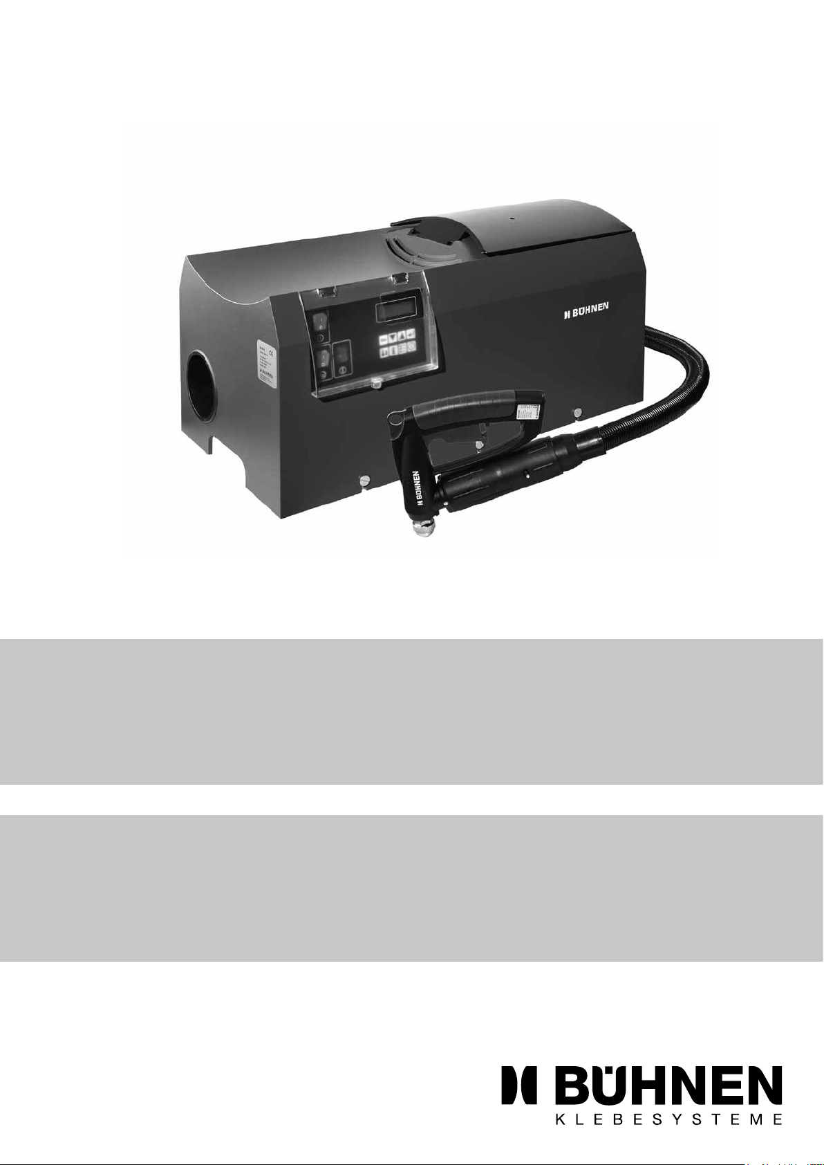
With the application system, the hot melt material is heated to high temperatures, con-
veyed to the application unit and discharged under pressure.
This security advice functions as industrial safety and accident prevention. Noncompliance
with the security advice can cause burns, injuries, or death by electricity and/or material
damage.
Your cooperation is required to protect you and other persons from harm:
• Always work cautiously.
• Always be aware that hazards are usually not obvious.
• Always use the requisite personal protective equipment for your safety at your work-
place.
2 General
The components of our application systems were designed and manufactured under con-
sideration of threat analysis and harmonized standards.
These components correspond to the status of technology and permit safe operation.
Danger!
Constructive changes may only be implemented after approval by the manufacturer.
2.1 Operator’s due diligence
The operation of the application system is only then safe when all requisite measures
have been made. It is the due diligence of the operator to initiate these measures and to
control its implementation.
Above all, the following must be guaranteed:
• that the application system is only used as intended,
• that the application system may only be operated in a faultless, functioning condition
and that the safety lugs are checked regularly,
• that the requisite personal protective equipment is available and is worn,
• that these operating instructions are always available in a legible and complete condi-
tion at the site of use,
• thatonlyqualiedandauthorizedpersonnel–seeChapter3–mayoperate,maintain,
and service the application system,
• that all safety and warning notices attached to the application system are not removed
and remain legible.

Recommended personnel
4
3 Recommended personnel
Activity Requirement
Initial operation Competent personnel
Facility/Retrotting
Operation Instructed personnel
Electrical maintenance/servicing Personnel competent in electrics
Mechanical maintenance/servicing Competent personnel
3.1 Competent personnel
Competentpersonsarethosepersonshavingsufcientknowledgeinaspecicfunctional
area due to their technical training and experience, and who are familiar with the relevant
industrial safety and accident prevention provisions as well as the generally acknowledged
rules of technology.
3.2 Instructed personnel
Instructed personnel are those persons having been instructed about the tasks assigned
to them and about the possible dangers due to improper conduct by a competent person
who also trains them, as required, in how to use the necessary safety equipment and
safety measures.
4 Possible hazards
Danger of burns!
Due to hot metal parts, hot melt material, and hot melt material vapors.
Therefore, always wear heat protection gloves.
Only operate the unit with complete protective covers.
Remark
Heat protection gloves are special gloves that protect the hands from being damaged
byexternalinuencesofthethermaltype,andespeciallyfromcontactheatandradiated
heat.
Irritation of mucous membranes!
Hot melt adhesives give off vapors that can have an annoying odorous effect. Therefore,
make sure you provide for adequate ventilation. Observe the processing bulletin and the
safety data sheet of the hot melt material.
In individual cases, improper processing can cause irritations of the mucous membranes.
Consult your doctor immediately!
Attention!
After the power feed has been interrupted, a residual voltage can still be present. Wait at
least 10 minutes before working on electrical components.
General Security Advice

Notes on safe operation
5
5 Notes on safe operation
• Only operate the application system with complete protective covers, closed hoods and
faultless safety systems.
• Before starting production, check the application system for signs of visible damage
and for faultless condition.
• Never point the application unit towards yourself or at other persons.
• Protect the application system from moisture and wetness.
• Observe the processing bulletin of the hot melt material.
• Always break the power feed (power supply during
- Maintenance and service works
- Defective and/or improperly functioning application system.
6 Notes on handling the batteries
The HB 5010 tank system control unit has a lithium battery. Please note the following
safety notes when handling this battery:
• Never cause the battery to short circuit (danger of explosion).
• The battery may not be opened nor dismantled.
• Thebatterymaynotbeoverheatedorbesubjectedtoopenre.
• Never clean the battery with water or aggressive liquids.
• Never use leaky or damaged batteries.
• Collect and dispose of used batteries in a proper manner to protect the environment.
7 Conduct in emergency situations
1. Immediately turn off the main switch.
2. Disconnect the power plug immediately.
3. Only put the unit back into operation after the emergency situation has been elimi-
nated.

Subject to changes © BÜHNEN GmbH & Co. KG/HB_5010_T2_GB_#B/180131/H
BÜHNEN GmbH & Co. KG
Hinterm Sielhof 25
28277 Bremen • Germany
Phone:+49 (0) 421 51 20 - 125
Fax: +49 (0) 421 51 20 - 260
www.buehnen.de

Translation of the original Operating Manual
Hot melt adhesive tank system
HB 5010
H5307XM (Release 01-2018)

2

Table of Contents
3
1 Special security advice.......................................................................................................... 5
1.1 Possible dangers..................................................................................................................................5
1.2 Intended use ........................................................................................................................................5
2 Technical data......................................................................................................................... 7
2.1 Productidentication............................................................................................................................7
3 Overview of HB 5010.............................................................................................................. 9
3.1 Construction .........................................................................................................................................9
3.2 Function .............................................................................................................................................10
3.3 Operating and display elements......................................................................................................... 11
3.3.1 Main switch....................................................................................................................................................... 12
3.3.2 Display.............................................................................................................................................................. 12
3.3.3 Keypad ............................................................................................................................................................. 12
4 Installation / Initial operation ............................................................................................. 15
4.1 Set-up / Installation ............................................................................................................................15
4.1.1 Electrical connection ........................................................................................................................................ 15
4.1.2 Mechanical connection (hoses) ....................................................................................................................... 15
4.2 First commissioning ...........................................................................................................................16
5 Operation .............................................................................................................................. 17
5.1 Filling the hot melt adhesive............................................................................................................... 17
5.2 Daily turning on ..................................................................................................................................17
5.3 Standby operation ..............................................................................................................................18
5.4 Turning off ..........................................................................................................................................18
5.4.1 Turning off in time-controlled operation............................................................................................................ 18
5.4.2 Turning off in manually-controlled operation .................................................................................................... 19
5.4.3 Turning off in emergencies............................................................................................................................... 19
6 Programming........................................................................................................................ 21
6.1 Introduction ........................................................................................................................................21
6.2 Navigation ..........................................................................................................................................22
6.3 Menu description................................................................................................................................23
6.3.1 Level 1 menu items .......................................................................................................................................... 23
6.3.1.1 Individual shutdown ..................................................................................................................................... 23
6.3.1.2 Operating mode ........................................................................................................................................... 23
6.3.1.3 Language..................................................................................................................................................... 23
6.3.1.4 Password ..................................................................................................................................................... 24
6.3.2 Level 2 menu items .......................................................................................................................................... 24
6.3.2.1 Temperatures............................................................................................................................................... 24
6.3.2.2 Time operation ............................................................................................................................................. 25
6.3.2.3 Date/Time .................................................................................................................................................... 25
6.3.2.4 System......................................................................................................................................................... 26
6.3.2.5 Load factory settings.................................................................................................................................... 26
6.3.3 Level 3 menu items .......................................................................................................................................... 27
6.3.3.1 Limit values.................................................................................................................................................. 27
6.3.3.2 Waiting time ................................................................................................................................................. 28
6.3.3.3 Pump settings .............................................................................................................................................. 28
6.3.3.4 Celsius / Fahrenheit..................................................................................................................................... 30
6.3.3.5 Sensor selection .......................................................................................................................................... 30

Table of Contents
4
6.3.3.6 Control parameters ...................................................................................................................................... 30
6.3.3.7 Optimization................................................................................................................................................. 31
7 Set-up/Retrot .................................................................................................................... 33
7.1 Removing / Replacing the Housing....................................................................................................33
7.2 Setting the pump pressure .................................................................................................................34
7.3 Changing the hot melt material ..........................................................................................................36
7.4 Releasing system pressure................................................................................................................36
7.5 Dismantling a heated hose................................................................................................................. 36
8 Maintenance / Servicing ...................................................................................................... 37
8.1 Maintenance intervals ........................................................................................................................37
8.2 Cleaning .............................................................................................................................................37
8.3 Replacing the back-up battery ...........................................................................................................38
8.4 Inspection and replacement of fuses .................................................................................................40
9 What happens if…................................................................................................................ 42
9.1 General errors ....................................................................................................................................42
9.2 Error messages in the display............................................................................................................43
10 Accessories .......................................................................................................................... 45
10.1 Spray-air adapter kit...........................................................................................................................45
10.1.1 Overview .......................................................................................................................................................... 45
10.1.2 Assembly.......................................................................................................................................................... 46
10.1.3 Setting the optimum working pressure............................................................................................................. 46
10.1.4 Maintenance..................................................................................................................................................... 47
11 Repairs .................................................................................................................................. 48
12 Warranty................................................................................................................................ 48
13 Disposal ................................................................................................................................ 48

Special security advice
5
1 Special security advice
Info
Please also note the “General Warning Notes” in Part 1 of this manual.
1.1 Possible dangers
Danger of burns
due to hot metal parts, hot melt material, and hot melt material vapors.
Therefore, always wear heat protection gloves.
Only operate the unit with complete protective covers.
Attention!
After the power feed has been interrupted, a residual voltage can still be present. Wait at
least 10 minutes before working on electrical components.
1.2 Intended use
The HB 5010 tank system is used to melt and convey hot melt materials.
Application of the hot melt materials is done using one or two heated hoses with one
manual application unit each.
The tank system is designed for commercial or industrial use.
Only hot melt materials that have been checked and released by the manufacturer may be
processed in the HB 5010 tank system. Reactive hot melt adhesives, such as PU (poly-
urethane) hot melt adhesives may not be processed.

Special security advice
6

Technical data
7
2 Technical data
Designation HB 5010
Dimensions (W x D x H) 720 mm x 360 mm x 360 mm
Weight 35 kg
Power supply 230 VAC/50 Hz
Max. power consumption 3,400 W
Max. current consumption 15 A at 230 V
Type of protection IP32
Class of protection 1
Temperature control Electronic 6-channel temperature controller
Heating capacity of tank and connection block 1,460 W
Permitted connected load per hose 1,440 W (The sum of output of hoses and guns may
not exceed 1710W.)
Permitted connected load for manual application unit 400 W (The sum of output of hoses and guns may
not exceed 1710W.)
Working temperature 40...210 °C
Temperature sensor Pt 100, alternatively Ni 120 for hose and
manual application unit
Hose connections 2
Overtemperature protection Yes, limited to 260 °C
Permitted ambient temperature 0…40 °C
Melting capacity 4.5 kg/h
Warming-up period approx. 30 minutes
Pump system Gear wheel pump
Pump capacity 26 kg/h
Drive Geared motor
Rotational speed of pump 65 r.p.m.
Bypass valve setting 35 bar; max. 55 bar
Usable tank volume 4.5 liters
Noise emission 72 dbA
2.1 Productidentication
These operating instructions apply to all HB 5010 basic units with the following illustrated
type plate.
HB 5010
Teile-Nr.: H530700
el. Anschluß:
220-240V AC / 3400W
Ser.-Nr.: 00xxx
Baujahr: 2016
Bremen - Germany / www.buehnen.de
Figure 2.1/1: Type plate on unit (example)
Two type plates are attached to the HB 5010 basic unit:
• on the left narrow side of the housing
• on the inside of the unit on the left side of the housing of the control electronics
(seefollowinggure)

Technical data
8
Figure 2.1/2: Location of type plate on the inside of the unit

Overview of HB 5010
9
3 Overview of HB 5010
3.1 Construction
ThefollowingguresshowtheHB5010tanksystemanditscomponentswithremoved
housing:
12
3
5
Figure 3.1/1: Front view
6
7
8
9
10
4
Figure 3.1/2: Back view

Overview of HB 5010
10
No. Designation
1 Console
2 Switch cabinet with temperature control and pump control
3 Hot melt adhesive tank with heat insulation
4 Receiver for remote control
5 Pump motor
6 Power cable
7 Electrical connection for Hose 2
8 Electrical connection for Hose 1
9 Adjusting screw for pump pressure
10 Connections for hoses (adhesive)
3.2 Function
The HB 5010 hot melt adhesive application system is used for melting and applying adhe-
sives (intended use).
All components are mounted onto a sturdy console made of sheet steel. The hot melt ad-
hesiveislledintothetank(3)insolidformandthenmelted.Thetemperatureofthehot
melt adhesive in the tank can be pre-set using the control unit. The temperatures for the
hoses and manual application units can also be pre-set individually.
The control electronics keep the temperatures of all components at the selected values.
If the control electronics become defective, an integrated temperature sensor switches off
the system to prevent overheating.
The tank system can be utilized in two operating modes:
• Time-controlled operation
The main switch remains turned on in this operating mode. Software controls the turn-
ing on and off. The turning on and off times can be programmed for each day of the
week.
A temperature drop (“standby”) can be programmed for work breaks to avoid the ad-
hesive from oxidizing too quickly. The times for standby operation can be individually
programmed for each day of the week. The “time-controlled” operating mode is optimal
for regular, predictable requirements (shift operation).
• Manually controlled operation
In the “manually controlled” operating mode, the tank system is turned on and off as
required using the main switch. This operating mode is suitable for irregular require-
ments.
The gear wheel pump conveys the melted adhesive through the hoses (max. of 2) to the
manual application units. The gear wheel pump can operate in two modes:
• Continuous operation
The gear wheel pump runs continuously. A bypass valve conveys the non-discharged
adhesive back into the tank.
• Requirement-controlled operation
The gear wheel pump is controlled by the manual application units via wireless remote
control. Follow-on time can be programmed at the control unit.

Overview of HB 5010
11
The entire system is a modular construction. All electrical connections are pluggable de-
signs. This guarantees that all components can be exchanged quickly.
All main parameters (temperature, operating conditions) are shown as four-line plain text
in the display of the control unit.
The control unit is programmed through menu-driven plain text entries. It is divided into
several password-protected levels to prevent faulty operation through non-authorized
personnel.
The parameters can be reset to the delivered state at any time.
3.3 Operating and display elements
All operating and display elements are combined in the control unit.
A four-line, illuminated display is used to display important process data in normal mode.
In the programming mode, all parameters that can be set with their values are displayed in
plain text. A clear menu structure guides the user through the programming mode.
Esc
0
I
0
I
1 2
3
4
5
Tank 12:32
Val=82
0
C
Set=1800C
Preheating time
Handcontrolled, wait
Figure 3.3/1: Operating and display elements of the control unit
Ser. No. Description
1 Main switch (On/Off)
2 Display, four lines, illuminated
3 Keypad
4 “Temperature reached” control lamp
5 Pump switch
The following chapters describe the function of the individual operating and display ele-
ments.

Overview of HB 5010
12
3.3.1 Main switch
The entire tank system is turned on and off with the main switch.
In the disconnected condition, the system is switched completely to zero current.
3.3.2 Display
The display shows the current process values in the normal mode:
1. Time
2. Target and actual values of tank, pump, hose, and pistol temperatures.
3. Operating conditions (time-controlled, manually controlled, heating mode on/off, etc.)
The process values of the individual components (tank, pump, Hose 1, Pistol 1, etc.) are
displayed in succession. The next display is switched to after approx. 3 seconds.
Tank 12:32
Act=82
0C
Set=1800C
Preheating time
Handcontrolled, wait
Figure 3.3.2/1: Display example (normal mode)
3.3.3 Keypad
Esc
Figure 3.3.3/1: Keypad
The keypad has 8 membrane keys which protects them from environmental effects. All
operating and programming entries are made using these keys. The functions of the keys
are described individually in the following:
Escape (Cancel)
Use this key to exit a menu function. You are taken to the next higher level in the menu
structure.
Down arrow
This key has 2 functions:
• When maneuvering in the menu structure, the cursor is moved down one line in the
display or moved to the next position.
• When entering a value, the current value is decreased.
Up arrow
This key has 2 functions:
• When maneuvering in the menu structure, the cursor is moved up one line in the dis-
play or moved back one position.
• When entering a value, the current value is increased.
.
Esc
Table of contents
Other Buhnen Melting Machine manuals