Build Worker BTCP250-150 User manual

BTCP250-150
FR TOURET À MEULER COMBINÉ
NL COMBI-SLIJPMACHINE
GB COMBINATION BENCH GRINDER
2010


FR
TOURET À MEULER
COMBINÉ
MISE EN GARDE
Pour votre propre sécurité, lisez préalablement
ce manuel d’utilisation avant d’utiliser
la machine.
CONSIGNES DE SÉCURITÉ
Lors d’emploi de la machine, observez
toujours scrupuleusement les consignes de
sécurité fournies ainsi que les consignes de
sécurité complémentaires ci-dessous.
Dans ce manuel sont employés les
pictogrammes suivants :
Risque de lésion corporelle ou
de dégâts matériels.
CONSIGNES DE SÉCURITÉ
COMPLÉMENTAIRES POUR LES TOURETS
À MEULER
n Portez toujours des lunettes de sécurité pendant le
meulage.
n Pendant le meulage, faites attention aux enfants
présents à proximité.
n Ne meulez jamais sans carter de protection autour
de la meule.
n Fixez toujours bien le support fixe.
n Le jeu entre le pare-étincelles et la meule ne doit
pas dépasser 2 mm.
n Le jeu entre le support fixe et la meule ne doit
jamais dépasser 2 mm.
n N’utilisez jamais des meules endommagées.
n Changez la meule si elle est usée plus de ± 40 mm
de diamètre.
SÉCURITÉ ÉLECTRIQUE
Vérifiez si le voltage mentionné
sur la plaque signalétique de la
machine correspond bien à la
tension de secteur présente
sur lieu.
DESCRIPTION
Votre touret à meuler a été conçu pour l’affûtage
d’outils en métal et en bois, comme les couteaux,
ciseaux et autres outils coupants.
1 Bouton marche/arrêt
2 Support fixe meule
3 Meule
4 Écran transparent
5 Pare-étincelles
6 Ruban abrasif
7 Support fixe de ruban abrasif
8 Trou de fixation
Mise en place de la machine
La machine doit être fixée sur un établi au
moyen de vis.
n Marquez les trous de fixation (8) sur l’établi.
n Percez aux endroits marqués des trous dont le
diamètre et la profondeur conviennent aux vis à
employer.
n Placez la machine sur l’établi et insérez les
vis dans les trous de fixation.
n Serrez fermement les vis.
Remplacement de la meule
n Retirez le carter de protection (3).
n Desserrez l’écrou (10).
n Retirez la flasque extérieure (11) et la
meule usée (3).
n Nettoyez les flasques (11 & 12).
n Placez une meule neuve.
n Placez la flasque extérieure contre la meule et
serrez l’écrou sur l’axe.
Serrez fermement l’écrou.
n Placez le carter de protection.
Avant de changer une meule,
retirez toujours d’abord la fiche
de la prise de courant.
Ne montez jamais une meule
fissurée.
Remplacez immédiatement une
meule fissurée. Si vous utilisez
une meule fissurée, celle-ci
peut éclater et provoquer des
accidents.
Remplacement du ruban abrasif
n Enlevez le carter du ruban (13).
n Desserrez le bouton de blocage (14).
n À l’aide de la languette (16), appuyez sur le ressort
(17) pour relâcher la tension sur le ruban abrasif (6).
Resserrez le bouton de blocage.
n Démontez le ruban abrasif usé.
n Placez le ruban abrasif neuf sur le rouleau
d’entraînement (18) et le rouleau supérieur (19).
n Vissez le bouton de serrage et enfoncez le rouleau
supérieur au maximum pour tendre le ruban abrasif.
n Resserrez le bouton de blocage. Au besoin
réglez la position du ruban abrasif en faisant tourner
la vis de réglage (15) vers l’intérieur ou vers
l’extérieur.
n Replacez le carter du ruban.
Avant de changer un ruban,
retirez toujours d’abord la fiche
de la prise de courant.
N’utilisez jamais un ruban
abrasif usé.
Remplacez immédiatement un
ruban abrasif usé. Un ruban
abrasif usé peut brûler lors de
l’utilisation et provoquer des
accidents.

Montage et réglage des pare-étincelles
Vous devez réajuster le pare-étincelles
régulièrement afin de compenser l’usure des
meules.
n Montez le pare-étincelles (5) au carter de
la meule (9) comme indiqué.
n Ajustez la distance la plus petite possible
entre le pare-étincelles et la meule (3), soit 2 mm
maximum.
n Vissez le pare-étincelles.
n Rabattez l’écran (4) en avant.
n Serrez l’écrou (20).
Le pare-étincelles protège vos
yeux et vos mains contre les
étincelles qui jaillissent durant
le meulage. C’est pourquoi
vous devez toujours travailler
avec un pare-étincelles.
Montage et réglage du support fixe pour la
meule
Vous devez toujours réajuster régulièrement les
supports fixes afin de compenser l’usure des
meules.
n Maintenez le support fixe (21) contre le côté du
carter de meule (9) et fixez-le en place au moyen
des écrous (22).
n Serrez les fixations à la main.
n Ajustez la distance la plus petite possible entre le
support fixe (21) et la meule (3), soit 2 mm
maximum.
n Serrez les fixations.
Montage et réglage du support fixe pour le
ruban abrasif
Le support fixe peut être monté en deux
positions différentes sur les œillets de
montage respectifs (23).
n Maintenez le support fixe (24) contre l’un
des oeillets de montage (23) et installez-le
au moyen du boulon (25) et de la vis (26).
n Serrez les fixations à la main.
n Ajustez la distance la plus petite possible
entre le support fixe (24) et le ruban
abrasif (6), soit 2 mm maximum.
n Serrez les fixations.
Instructions d’emploi
n Avant de mettre la machine en marche, vérifiez si
toutes les vis et tous les écrous sont bien serrés et
si le ruban abrasif peut tourner sans rencontrer de
résistance.
n Meulez toujours à l’avant de la meule ou du ruban
abrasif. Ne sollicitez jamais la machine au point que
la meule ou le ruban abrasif s’immobilise.
n Utilisez la meule pour meuler des outils en
métal. Refroidissez régulièrement à l’eau les outils à
couper.
n Utilisez le ruban abrasif pour meuler les outils en
bois.
n La machine n’est pas appropriée pour un usage
continu. Assurez-vous que la machine ne connaisse
pas de surchauffe. Après 30 minutes d’utilisation,
laissez la machine refroidir jusqu’à la température
ambiante.
Mise en marche et arrêt
n Pour mettre la machine en marche, positionnez le
bouton marche/arrêt (1) sur ‘I’.
n Pour mettre la machine en arrêt, positionnez le
bouton marche/arrêt sur ‘0’.
NETTOYAGE ET ENTRETIEN
La machine n’exige pas d’entretien particulier.
n Éliminez régulièrement la poussière de meulage
du logement et des carters des protection.
SPÉCIFICATIONS TECHNIQUES
Tension du réseau V 230
Fréquence du réseau Hz 50
Puissance W 250
Vitesse min-1 2.950
Épaisseur max. de la meule mm 20
Diamètre de la meule mm 150
Diamètre du trou d’axe mm 12,7
Largeur du ruban abrasif. mm 50
Longueur du ruban abrasif. mm 686
Poids kg 8,1
Niveau de la pression sonore mesuré sur le
lieu de travail conformément à la norme
EN 50144:
LpA (pression sonore) dB(A) < 75
GARANTIE
Pour les clauses de garantie, reportez-vous
aux conditions de garantie ci-jointes.
ENVIRONNEMENT
Si, après un certain temps,
vous décidez de remplacer
votre machine, ne vous en
débarrassez pas avec les
ordures ménagères mais
destinez-la à un traitement
respectueux de
l’environnement.
Fabriqué en Chine 2010

NL
COMBI-SLIJPMACHINE
WAARSCHUWING
Lees voor uw eigen veiligheid deze
gebruiksaanwijzing goed door alvorens de
machine te gebruiken.
VEILIGHEIDSVOORSCHRIFTEN
Volg bij gebruik van de machine altijd de
bijgeleverde veiligheidsvoorschriften en
onderstaande aanvullende
veiligheidsvoorschriften nauwkeurig op.
In deze handleiding worden de volgende
pictogrammen gebruikt:
Gevaar voor lichamelijk letsel
of materiële schade.
AANVULLENDE
VEILIGHEIDSVOORSCHRIFTEN VOOR
WERKBANKSLIJPMACHINES
n Draag tijdens het slijpen altijd een
veiligheidsbril.
n Pas op voor kinderen in de buurt tijdens
het slijpen.
n Slijp nooit zonder beschermkap om de
steen.
n Zet de leunspaan altijd goed vast.
n De speling tussen de vonkenvanger en de
steen mag niet meer dan 2 mm bedragen.
n De speling tussen leunspaan en slijpsteen
mag nooit meer dan 2 mm bedragen.
n Gebruik nooit beschadigde slijpstenen.
n Vervang de slijpsteen als de diameter door
slijtage meer dan ca. 40 mm is afgenomen.
ELEKTRISCHE VEILIGHEID
Controleer of de op het
typeplaatje van de machine
vermelde spanning
overeenkomt met de ter plaatse
beschikbare netspanning.
BESCHRIJVING
Uw combi-slijpmachine is ontworpen voor
het scherpen van metalen en houten
gereedschappen, zoals messen, beitels en
overig snijgereedschap.
1 Aan/uit-schakelaar
2 Leunspaan slijpsteen
3 Slijpsteen
4 Transparant scherm
5 Vonkenvanger
6 Slijpband
7 Leunspaan slijpband
8 Bevestigingsgat
Plaatsen van de machine
De machine moet met schroeven op een
werkbank worden bevestigd.
n Teken op de werkbank de
bevestigingsgaten (8) af.
n Boor op de afgetekende plaatsen gaten
met de juiste doorsnede en diepte voor de
te gebruiken schroeven.
n Plaats de machine op de werkbank en steek
de schroeven door de bevestigingsgaten.
n Draai de schroeven goed vast.
Verwisselen van de slijpsteen
n Verwijder de beschermkap (9).
n Draai de moer (10) los.
n Verwijder de buitenste flens (11) en de
oude slijpsteen (3).
n Maak de flenzen (11 & 12) schoon.
n Plaats een nieuwe slijpsteen.
n Plaats de buitenste flens tegen de
slijpsteen en draai de moer op de as.
Draai de moer goed vast.
n Plaats de beschermkap.
Neem voor het verwisselen van
een slijpsteen altijd eerst de
netstekker uit het stopcontact.
Monteer nooit een gebarsten
slijpsteen. Vervang een
gebarsten slijpsteen
onmiddellijk.
Een gebarsten slijpsteen kan
bij gebruik uit elkaar springen
en ongelukken veroorzaken.
Verwisselen van de slijpband
n Verwijder de beschermkap (13).
n Draai de schroef (14) los.
n Druk met behulp van de lip (16) de veer
(17) in om de spanning op de slijpband (6)
op te heffen. Draai de schroef vast.
n Verwijder de oude slijpband.
n Leg de nieuwe slijpband achtereenvolgens
over de aandrijfrol (18) en de bovenste rol (19).
n Maak de schroef los en duw de bovenste
rol zo ver naar achteren dat de slijpband op
spanning komt.
n Draai de schroef vast. Stel de positie van
de slijpband eventueel bij door de instelschroef (15)
in of uit te draaien.
n Plaats de beschermkap.
Neem voor het verwisselen van
een slijpband altijd eerst de
netstekker uit het stopcontact.
Monteer nooit een gescheurde
slijpband. Vervang een
gescheurde slijpband
onmiddellijk.
Een gescheurde slijpband kan
bij gebruik uit elkaar springen
en ongelukken veroorzaken.

Monteren en instellen van de
vonkenvanger
U dient de vonkenvanger regelmatig bij te
stellen om de slijtage van de slijpsteen te
compenseren.
n Bevestig de vonkenvanger (5) aan de
beschermkap (9) zoals afgebeeld.
n Stel de afstand tussen de vonkenvanger
en de slijpsteen (3) zo klein mogelijk in,
tot maximaal 2 mm.
n Schroef de vonkenvanger vast.
n Klap het scherm (4) naar voren.
n Draai de moer (20) vast.
De vonkenvanger beschermt
uw ogen en handen tegen
wegspattende vonken.
Werk daarom altijd met een
vonkenvanger.
Monteren en instellen van de leunspaan
voor de slijpsteen
U dient de leunspaan regelmatig bij te stellen
om de slijtage van de slijpsteen te compenseren.
n Houd de leunspaan (21) tegen de zijkant
van de beschermkap (9) en bevestig hem
met behulp van de bouten (22).
n Draai de bevestigingsmiddelen handvast.
n Stel de afstand tussen de leunspaan (21)
en de slijpsteen (3) zo klein mogelijk in, tot
maximaal 2 mm.
n Draai de bevestigingsmiddelen vast.
Monteren en instellen van de leunspaan
voor de slijpband
U kunt de leunspaan op twee verschillende
posities aan de voor dat doel aangebrachte
montageogen (23) monteren.
n Houd de leunspaan (24) tegen de een van
de montageogen (23) en bevestig hem
met behulp van de bout (25) en de
schroef (26).
n Draai de bevestigingsmiddelen handvast.
n Stel de afstand tussen de leunspaan (24)
en de slijpband (6) zo klein mogelijk in, tot
maximaal 2 mm.
n Draai de bevestigingsmiddelen vast.
Aanwijzingen voor gebruik
n Controleer voordat u de machine inschakelt
of alle schroeven en moeren vastzitten en
of de slijpsteen en de slijpband zonder
weerstand kan ronddraaien.
n Slijp steeds aan de voorzijde van de
slijpsteen of slijpband. Belast de machine
nooit zodanig dat de slijpsteen of slijpband tot
stilstand komt.
n Gebruik de slijpsteen voor het slijpen van metalen
gereedschappen. Koel de te slijpen
gereedschappen regelmatig af met water.
n Gebruik de slijpband voor het slijpen van houten
gereedschappen.
n De machine is niet geschikt voor continugebruik.
Let op dat de machine niet oververhit raakt. Laat de
machine na 30 minuten gebruik afkoelen tot
omgevingstemperatuur.
In- en uitschakelen
n Om de machine in te schakelen, zet u de
aan/uit-schakelaar (1) op ‘I’.
n Om de machine uit te schakelen, zet u de
aan/uit-schakelaar op ‘0’.
REINIGING EN ONDERHOUD
De machine vergt geen speciaal onderhoud.
n Verwijder regelmatig slijpselafval van de
behuizing en uit de beschermkasten.
TECHNISCHE GEGEVENS
Netspanning V 230
Netfrequentie Hz 50
Vermogen W 250
Toerental min-1 2.950
Max. dikte slijpsteen mm 20
Diameter slijpsteen mm 150
Diameter asgat mm 12,7
Breedte slijpband mm 50
Lengte slijpband mm 686
Gewicht kg 8,1
Niveau van de geluidsdruk op de werkplek
gemeten volgens EN 50144:
LpA (geluidsdruk) dB(A) < 75
GARANTIE
Voor de garantiebepalingen wordt verwezen
naar de bijgevoegde garantievoorwaarden.
MILIEU
Als uw machine na verloop van
tijd aan vervanging toe is, geef
hem dan niet met het huisvuil
mee, maar zorg voor een
milieuvriendelijke verwerking.
Made in China 2010

GB
COMBINATION BENCH
GRINDER
WARNING
Read this manual carefully before using the
machine, for your own safety.
SAFETY INSTRUCTIONS
When using the machine, always observe
the enclosed safety instructions as well as
the additional safety instructions.
The following symbols are used throughout
this manual:
Denotes risk of personal injury
or damage to the tool.
ADDITIONAL SAFETY INSTRUCTIONS FOR
BENCH GRINDERS
n Always wear safety goggles while grinding.
n Keep children out of the work area.
n Never operate the grinder without the wheel guard
in place.
n Always securely fix the workpiece support.
n The distance between the spark guard and the
grinding wheel must not exceed 2 mm.
n The distance between the workpiece support and
the grinding wheel must not exceed 2 mm.
n Never use damaged grinding wheels.
n Replace the grinding wheel when it has worn by
more than approx. 40 mm.
ELECTRICAL SAFETY
Always check that the power
supply corresponds to the
voltage on the rating plate.
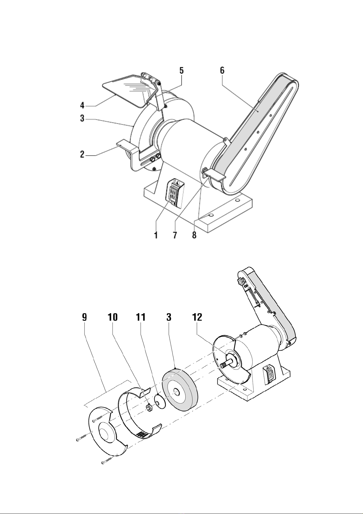
DESCRIPTION
Your combination bench grinder has been
designed for sharpening metal and wooden
tools, including knives, chisels and other
cutting tools.
1 On/off switch
2 Workpiece support grinding wheel
3 Grinding wheel
4 Transparant screen
5 Spark guard
6 Grinding belt
7 Workpiece support grinding belt
8 Mounting hole
Mounting the machine
The machine must be screwed to a workbench.
n Mark the position of the mounting holes (8)
on the workbench.
n Drill holes at each of the marked
positions, adjusting the diameter and
depth of the holes to the screws used.
n Place the machine on the workbench and
insert the screws into the mounting holes.
n Firmly tighten the screws.
Replacing the grinding wheel
n Remove the wheel guard (9).
n Loosen the nut (10).
n Remove the outer flange (11) and the old
grinding wheel (3).
n Clean the flanges (11 & 12).
n Place a new grinding wheel.
n Place the outer flange against the grinding
wheel and place the nut onto the spindle.
Securely tighten the nut.
n Replace the wheel guard.
Always unplug the tool before
replacing a grinding wheel.
Never use a cracked grinding
wheel. Immediately replace a
cracked grinding wheel.
A cracked grinding wheel may
break into pieces when used
and cause accidents.
Replacing the grinding belt
n Remove the belt guard (13).
n Loosen the locking knob (14).
n Using the lip (16) press the spring (17) to
release the tension on the grinding belt (6).
Tighten the locking knob.
n Remove the old grinding belt.
n Successively place the new grinding belt over
the drive roll (18) and the upper roll (19).
n Loosen the locking knob and push the upper roll
as much to the rear to tension the grinding belt.
n Tighten the locking knob. If necessary adjust the
position of the grinding belt by turning the set screw
(15) in or out.
n Replace the belt guard.
Always unplug the tool before
replacing a grinding belt.
Never use a torn grinding belt.
Immediately replace a torn
grinding belt. A torn grinding
belt may burst when used and
cause accidents.
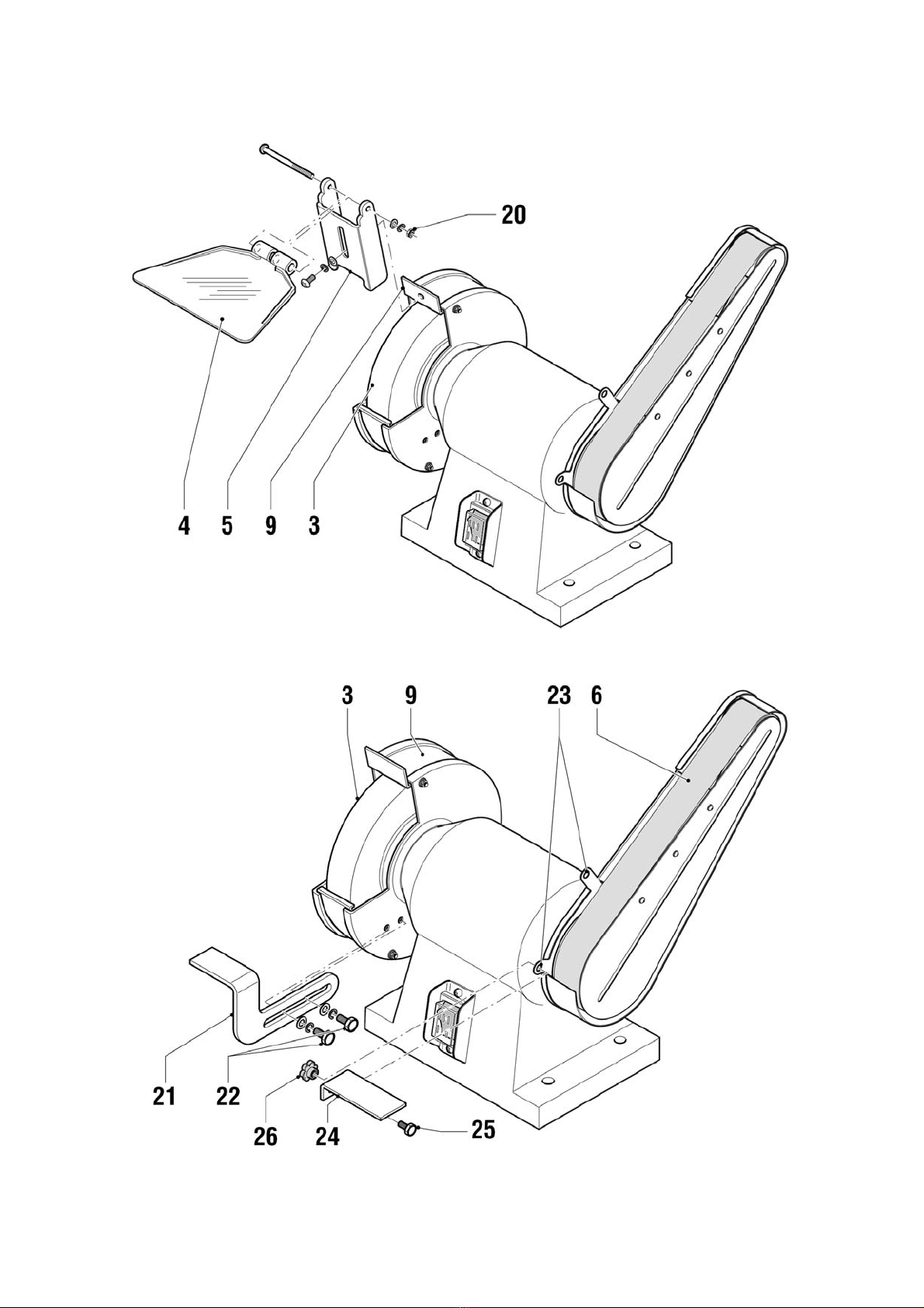
Mounting and adjusting the spark guard
You must regularly adjust the spark guard in order
to compensate the wear of the grinding wheel.
n Mount the spark guard (5) to the wheel guard (9)
as shown.
n Adjust the distance between the spark guard
and the grinding wheel (3) to the smallest possible
value, with a maximum of 2 mm.
n Tighten the spark guard screw.
n Slide the screen (4) to the front.
n Tighten the nut (20).

The spark guard protects your
eyes and hands from sparks
flying from the workpiece.
Therefore, always use the spark
guard.
Mounting and adjusting the workpiece
support for the grinding wheel
You must regularly adjust the workpiece support in
order to compensate the wear of the grinding wheel.
n Hold the workpiece support (21) against the side
of the wheel guard (9) and fit it using the bolts (22).
n Tighten the fasteners handtight.
n Adjust the distance between the
workpiece support (21) and the grinding wheel (3) to
the smallest possible value,
with a maximum of 2 mm.
n Tighten the fasteners.
Mounting and adjusting the workpiece
support for the grinding belt
The workpiece support can be mounted at two
different positions to the respective mounting
eyes (23).
n Hold the workpiece support (24) against one of
the mounting eyes (23) and fit it using the bolt (25)
and the screw (26).
n Tighten the fasteners handtight.
n Adjust the distance between the workpiece
support (24) and the grinding belt (6) to the smallest
possible value, with a maximum of 2 mm.
n Tighten the fasteners.
Instructions for use
n Before switching on the machine, check if all
screws and nuts are tight and if the grinding belt can
rotate freely.
Always grind on the front part of the grinding wheel
or grinding belt.
Never overcharge the machine, causing the grinding
wheel or grinding belt to come to a halt.
n Use the grinding wheel for grinding metal
tools. Regularly cool the tools to be cut with water.
n Use the grinding belt for grinding wooden tools.
n The machine is not intended for permanent use.
Make sure that the machine is not overheated.
After using the machine for 30 minutes, let it cool
down to ambient temperature.
Switching on and off
n To switch the machine on, set the on/off
switch (1) to ‘I’.
n To switch the machine off, set the on/off
switch (1) to ‘0’.
CLEANING AND MAINTENANCE
The machine does not require any special
maintenance.
n Regularly remove grindings from the housing and
the covers.
TECHNICAL DATA
Mains voltage V 230
Mains frequency Hz 50
Power input W 250
Speed min-1 2,950
Max. thickness grinding wheel mm 20
Diameter grinding wheel mm 150
Wheel bore mm 12.7
Width grinding belt mm 50
Length grinding belt mm 686
Weight kg 8.1
Level of sound pressure measured
according to EN 50144:
LpA (sound pressure) dB(A) < 75
GUARANTEE
Refer to the enclosed guarantee conditions
for the terms and conditions of guarantee.
ENVIRONMENT
Should your machine need
replacement after extended
use, do not put it in the
domestic waste but dispose of
it in an environmentally safe
way.
Made in China 2010

81, rue de Gozée
6110 Montigny-le-Tilleul
Belgique
Tél : 0032 71 29 70 70 Fax : 0032 71 29 70 86
Made in China
S.A.V
32 / 71 / 29 . 70 . 88 32 / 71 / 29 . 70 . 99
Service Parts separated
32 / 71 / 29 . 70 . 83 32 / 71 / 29 . 70 . 86
2010 Made in China
This manual suits for next models
1
Table of contents
Languages:
Other Build Worker Grinder manuals
Popular Grinder manuals by other brands

Dexter Laundry
Dexter Laundry 20VAG3-125BL.1 instruction manual

SCANMASKIN
SCANMASKIN FEROX 200 manual

Universal Tool
Universal Tool UT8720-20 General Safety Information & Replacement Parts

Metabo
Metabo BFE 9-20 Original instructions

Black & Decker
Black & Decker 7" instruction manual

Hitachi
Hitachi GP 10DL Handling instructions