Bull OUTLAW 26038 Quick reference guide

30 INCH GRILL HEADS
ASSEMBLY & OPERATING INSTRUCTIONS
OUTLAW LONESTAR SELECT ANGUS
MODEL #26038 (L.P.) MODEL #87048 (L.P.) MODEL #47628 (L.P.)
MODEL #26039 (N.G.) MODEL #87049 (N.G.) MODEL #47629 (N.G.)
DANGER
If you smell gas:
•
Shut off gas to the appliance.
•
Extinguish any open flame.
•
Open lid.
•
If odor continues, keep away from
the appliance and immediately call
your gas supplier or your
fire department.
WARNING
•
Do not store or use gasoline
or other flammable liquids
or vapors in the vicinity of
this or any other appliance.
•
An LP cylinder not
connected for use shall
not be stored in the
vicinity of this or any
other appliance.
USA EDITION

2
TABLE OF CONTENTS PAGE #
SAFETY INSTRUCTIONS2
GRILL OPERATIONAL SAFETY............................................................................................................................................................................... 3
CHECKING FOR GAS LEAKS.................................................................................................................................................................................. 4
LIQUID PROPANE GAS SAFETY ............................................................................................................................................................................ 5
LIQUID PROPANE TO NATURAL GAS CONVERSION……………………………………………………………………………………………………..6
NATURAL GAS SAFETY…………………………………………………………………………………………………………………………………………6
INSTALLATION INSTRUCTIONS
GRILL LOCATION.................................................................................................................................................................................................... .7
GRILL VENTILATION................................................................................................................................................................................................ 7
GRILL VENTILATION WHEN INSTALLED INTO ISLANDS FOR ENCLOSURES………………………………………………………………………..8
LP GAS CONNECTION SPECIFICATIONS FOR ISLANDS AND ENCLOSURE.................................................................................................... 9
LP GAS TANK RETENTION.................................................................................................................................................................................... 10
NATURAL GAS CONNECTION SPECIFICATIONS FOR ISLANDS AND ENCLOSURE...................................................................................... 11
GRILL LIGHTING SYSTEM TRANSFORMER INSTALLATION............................................................................................................................. 12
GRILL OPERATION AND COOKING GUIDELINES
FIRST USE AND LIGHTING INSTRUCTIONS AND SAFETY……………………………………………………………………………………………13-15
COOKING COMPONENT INSTALLATION AND BASIC COOKING METHODS AND SAFETY……………………………………………………….16
ROTISSERIE SYSTEM OPERATION ………………………………………………………………………………………………………………………17
GRILL BURNER REMOVAL INSPECTION / CLEANING BURNERS AND GAS VALVE ORIFICES BURNER CLEANING
BURNER REMOVAL INSTRUCTIONS.………………………………………………………………………………………………………………………18
BURNER INSPECTION AND CLEANING .............................................................................................................................................................. 19
BURNER SHUTTER CLIP INSPECTION AND ADJUSTMENT……………………………………………………………………………………………19
BACK BURNER ORIFICE AIR INLET GUARD INSPECTION AND INSTALLATION……………………………………………………………………19
INSTALLING BURNERS BACK INTO GRILL ......................................................................................................................................................... 20
IGNITOR / ELECTRODE CHECK……………………………………………………………………………………………………………………………..20
GRILL LIGHTING SYSTEM
LIGHT BULB REPLACEMENT................................................................................................................................................................................ 21
LIGHT SYSTEM CONNECTION DIAGRAM ........................................................................................................................................................... 21
ANNUAL CLEANING & MAINTENANCE .........................................................................................................................................................22-23
TROUBLESHOOTING………………………………................................................................................................................................................24
IF GRILL FAILS TO OPERATE PROPERLY………………………………………………………………………………………………………………..24
YELLOW FLAME AND FLASH BACK................................................................................................................................................................... 24
HOW TO REGISTER YOUR GRILL, SERIAL NO. LOCATION, REPLACEMENT PART ORDERING… .............................................................. 25
OUTLAW REPLACEMENT PARTS LIST AND REFERENCE DRAWING ......................................................................................................26-27
LONESTAR SELECT REPLACEMENT PARTS LIST AND REFERENCE DRAWING ............................................................................……28-29
ANGUS REPLACEMENT PARTS LIST AND REFERENCE DRAWING ......................................................................................................... 30-31
ROTISSERIE PARTS LIST AND EXPLODED ILLUSTRATION............................................................................................................................ 32
LIMITED WARRANTY POLICY......................................................................................................................................................................... 33-35
READ THIS ENTIRE MANUAL CAREFULLY AND RETAIN FOR FUTURE REFERENCE
.
BE SURE YOUR GRILL IS PROPERLY INSTALLED, ASSEMBLED AND CARED FOR. FAILURE TO FOLLOW THESE INSTRUCTIONS MAY RESULT IN SERIOUS BODILY
INJURY AND/OR PROPERTY DAMAGE. IF YOU HAVE QUESTIONS CONCERNING ASSEMBLY OR OPERATION, CONSULT YOUR DEALER, GAS APPLIANCE SERVICE
REPRESENTATIVE OR YOUR GAS COMPANY.
-
NOTE TO INSTALLER: LEAVE THESE INSTRUCTIONS WITH THE CONSUMER AFTER INSTALLATION.
-
NOTE TO THE CONSUMER: RETAIN THESE INSTRUCTIONS FOR FUTURE REFERENCE.
-
THIS OUTDOOR COOKING GAS APPLIANCE IS NOT INTENDED TO BE INSTALLED IN OR ON RECREATIONAL VEHICLES AND/OR BOATS.
*FOR WARRANTY PURPOSES, PLEASE RECORD YOUR MODEL NUMBER, SERIAL NUMBER, DATE OF PURCHASE ON THE REGISTRATION CARD ON PAGE 25
ALONG WITH ATTACHING A COPY OF YOUR RECEIPT OR INVOICE TO PAGE 25.
v.2022.06.28
WARNING: Fuels used in gas or oil-fired appliances and the
products of combustion of such fuels, contain chemicals known to
the State of California to cause cancer, birth defects and/or
reproductive harm. This warning is issued pursuant to California
Health & Safety Code Sec. 25249.6.

3
SAFETY INSTRUCTIONS
GRILL OPERATIONAL SAFETY
WARNING! FOR YOUR SAFETY, READ THE GUIDELINES BELOW
FOR ASSEMBLY AND OPERATION OF YOUR GRILL.
YOUR GAS GRILL IS ONLY FOR OUTDOOR USE.
PROTECT CHILDREN: DO NOT ALLOW CHILDREN TO OPERATE
GRILL. KEEP THEM AWAY FROM THE GRILLDURING USE, AND UNTIL
THE GRILL HAS COOLED COMPLETELY.
WARNING:
DO NOT USE YOUR GAS GRILL UNDER EXTENDED
AWNINGS, GARAGES, PORCHES, BREEZEWAYS,SHEDS OR OTHER
ENCLOSED AREAS. FAILURE TO DO SO COULD RESULT IN A FIREOR
PERSONAL INJURY.
DANGER:
DO NOT PUT GRILL IN STORAGE OR TRAVEL
MODE IMMEDIATELY AFTER USE. ALLOW GRILL TO COOL
TO TOUCH BEFORE MOVING OR STORAGE.FAILURE TO DO
SO COULD RESULT IN FIRE RESULTING IN PROPERTY
DAMAGE, PERSONAL INJURY OR DEATH.
WARNING: The outdoor cooking gas appliance, when
installed, must be electrically grounded in accordance
with local codes or, in the absence of local codes, with the
National Electrical Code, ANSI/NFPA 70, or the Canadian
Electrical Code, Part I, CSA C22.1.
a) To protect against electric shock, do not immerse cord or plugs
in water or other liquid.
b) Unplug from the outlet when not in use and before cleaning. Allow to cool before putting on or taking off parts.
c) Do not operate any outdoor cooking gas appliance that has malfunctioned or been damaged in any manner, such as a damaged
power cord or plug. Contact the manufacturer for repair.
d) Do not let the cord hang over the edge of a table or touch hot surfaces.
e) Do not use an outdoor cooking gas appliance for purposes other than intended
f) When connecting, first connect plug to the outdoor cooking gas appliance then plug appliance into the outlet
g) Use only a Ground Fault Interrupter (GFI) protected circuit with this outdoor cooking gas appliance.
h) Never remove the grounding plug or use with an adapter of 2 prongs.
i) Use only extension cords with a 3 prong grounding plug, rated for the power of the equipment, and approved for outdoor use with
a W-A marking.
ADDITIONAL SAFETY INSTRUCTIONS:
THIS GRILL IS NOT INTENDED FORUSE IN OR ON RECREATIONAL VEHICLES AND/OR BOATS.
DO NOT PLACE GRILL UNDER OR ON TOP OF AN SURFACE THAT WILL BURN
.
DO NOT ALLOW OBSTRUCTION OR RESTRICTION TO THE FLOW OF COMBUSTION AND VENTILATION AIR AROUND THE GRILL HOUSING.
GRILL CLEARANCE FROM THE BACK AND SIDE OF ANY COMBUSTIBLE SURFACE MUST BE AT LEAST 21 INCHES. DO NOT STORE
OR USE GASOLINE, OR OTHER LIQUIDS EMITTING FLAMMABLE VAPORS IN THE VICINITY OF GRILL OR ANY OTHER APPLIANCES.
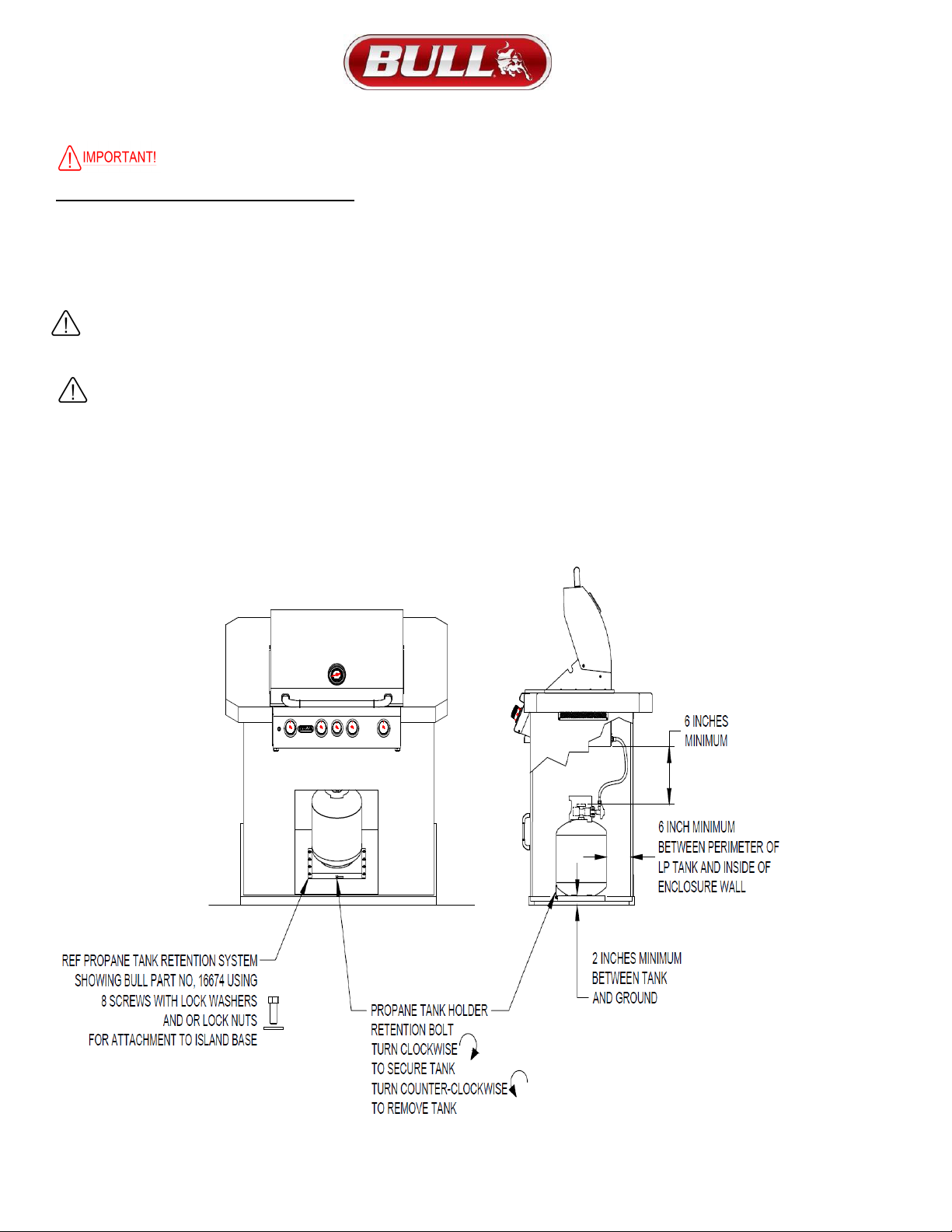
DO NOT STORE EMPTY OR FULL SPARE LP GAS CYLINDERS AND/OR CHEMICALS UNDER OR NEAR GRILL OR ANY OTHER APPLIANCES.
KEEP THE FUEL HOSE AND ELECTRICAL CORDS AWAY FROM HOT SURFACES AND DRIPPING GREASE. CHECK AND CLEAN BURNER
VENTURI TUBES FOR INSECTS AND DEBRIS. A CLOGGED TUBE CAN LEAD TO A FIRE BENEATH THE GRILL.
KEEP THE VENT OPENINGS OF THE CYLINDER ENCLOSURE FREE AND CLEAR FROM DEBRIS.CLEAN OUTDOOR COOKING GAS
APPLIANCE WITH RECOMMENDED CLEANING AGENTS.
AVOID UNNECESSARY TWISTING OF THE HOSE. VISUALLY INSPECT THE HOSE PRIOR TO EACH USE FOR CUTS, CRACKS,
EXCESSIVE WEAR OR OTHER DAMAGE AND REPLACE IF NECESSARY. THE REPLACEMENT HOSE SHOULD BE THAT SPECIFIED BY
THE MANUFACTURER.
NEVER LIGHT GRILL WITH LID CLOSED OR BEFORE CHECKING TO ENSURE BURNER TUBES ARE FULLY SEATED OVER GAS
VALVE ORIFICES.
NEVER LEAN OVER COOKING SURFACE WHILE LIGHTING GRILL. USE BARBECUE TOOLS WITH WOOD HANDLES AND
GOOD QUALITY INSULATED OVEN MITTS WHEN OPERATING GRILL.
NEVER PLACE OBJECTS OR UTENSILS ON TOP OF GRILL LID.
WARNING: IF THESE GUIDELINES ARE NOT FOLLOWED, FIRE CAUSING SERIOUS INJURY OR DEATH MAY OCCUR.
DUE TO SPIDER WEBS
CAUTION: BURNERS MUST BE INSPECTED AND
CLEANED BEFORE FIRST USE.
Spiders and small insects occasionally spin webs or make
nestsin the burners during warehousing, transit and/or after
long periods of non- use. These webs can lead to a gas flow
obstruction, which could result in a fire in and around the
burner venturi tubes. This type of fire is known as “FLASH-
BACK” and can cause serious damage to your grill and
create an unsafe operating condition for the user. Although
an obstructed burner tube is not the only cause of “FLASH
BACK” itis the most common cause, and frequent inspection
and cleaning of the burners is necessary.
WARNING
NEVER cover slots, holes or openingsin the grill bottom or
cover an entire cooking grate with material such as
aluminium foil. Doing so blocks air flow through the oven
and may causecarbon monoxide poisoning.
Aluminium foil linings may trap heat causinga fire hazard.

4
GRILL OPERATIONAL SAFETY (CONTINUED)
WARNING! FOR YOUR SAFETY...
1) DO NOT store or use gasoline or other flammable vapors and liquids in the vicinity of this or any other
appliance.
2) DO NOT store empty or full spare gas cylinders and/or chemicals under or near this or any other appliance.
3) Keep the fuel hose away from hot surfaces. Protect the fuel hose from dripping grease. Avoid unnecessary
twisting of the hose. Visually inspect the hose prior to each use for cuts, cracks excessive wear or other
damage and replace if necessary.
4) NEVER test for gas leaks with a lighted match or open flame.
5) NEVER light grill with lid closed or before checking to ensure burner tubes are fully seated over gas valve
orifices.
6) NEVER lean over cooking surface while lighting grill. Use barbecue tools with wood handles and good
quality insulated oven mitts when operating grill.
7) Keep any electrical supply cord and the fuel supply hose away from any heated surfaces.
DANGER! IF YOU SMELL GAS...
1) Shutoff gas to the appliance at its source.
2) Extinguish any open flame.
3) Open grill lid to release any accumulation of fumes.
4) If gas odor persists, immediately contact your gas supplier or your fire department.
WARNING: IF THESE GUIDELINES ARE NOT FOLLOWED, FIRE CAUSING SERIOUS INJURY OR DEATH MAY OCCUR.
CHECKING FOR GAS LEAKS
NEVER TEST FOR GAS LEAKS WHILE THE GRILL IS LIT!
Prior to the first use and at the beginning of each new season (or, if using LP, whenever gas cylinder is changed), it is a must that you
check for gas leaks.
Follow these steps:
1) Make a soap solution by mixing 1 part liquid detergent and one part water.
2) Turn off heat control valves, and then turn on gas at source.
3) Apply the soap solution to all gas connections: bubbles will appear in the soap solution if connections are not properly sealed,
tighten or repair as necessary.
4) If you have a gas leak that you cannot repair, turn off the gas at the source, disconnect fuel line from the double side burner and
immediately call your dealer and gas supplier for professional assistance.
WHEN THE OUTDOOR COOKING GAS APPLIANCE IS NOT IN USE
WARNING: When the outdoor cooking gas appliance is not in use, the gas supply must be turned off at the supply cylinder. Storage
of an outdoor cooking gas appliance indoors is permissible only if the cylinder is disconnected and removed from the outdoor cooking
gas appliance.
1) Cylinder must be stored outdoors, out of reach of children and must not be stored in a building, garage or any other enclosed area.
2) Place dust cap on cylinder valve outlet whenever the cylinder is not in use. Only install the type of dust cap on
the cylinder valve outlet that is provided with the cylinder valve. Other types of caps or plugs may result in leakage of propane.
3) Do not store a spare LP gas cylinder under or near this appliance.
4) Never fill the cylinder beyond 80 percent full.
5) If the information in 1) and Clause 2) is not followed exactly, a fire causing death or serious injury may occur.

5
LIQUID PROPANE (LP) SAFETY GUIDELINES
Your Propane gas grill is designed to operate on propane gas ONLY, at a pressure regulated at 11” water column (W.C.)
when equipped with the correct propane orifices on the valves and a propane regulator on the supply line regulated at the
residential meter. Your propane gas grill is designed to be used with a standard 20 lb. gas cylinder with size of 46cm
(Height) / 18.1in * 32cm (Width) / 12.5in. In the United States, the gas cylinder must be constructed and marked in
accordance with specifications of the US Department of Transportation for Propane Gas Cylinders.
1) ALWAYS KEEP LP GAS CYLINDER SECURELY FASTENED IN AN UPRIGHT POSITION.
2) NEVER CONNECT AN UNREGULATED LP GAS CYLINDER TO THE GRILL.
3) DO NOT SUBJECT LP GAS CYLINDERS TO EXCESSIVE HEAT.
4) DO NOT STORE SPARE LP GAS CYLINDERS UNDER OR NEAR THIS APPLIANCE.
5) DO NOT FILL LP GAS CYLINDER BEYOND 80% FULL.
IF WARNING NOTICES 1 AND 2 ARE NOT FOLLOWED, A FIRE CAUSING SERIOUS INJURY OR DEATH MAY OCCUR
6) CAUTION: CHANGING THE GAS TANKS MUST BE DONE AWAY FROM ANY SOURCE OF IGNITION.
7) LP GAS TANK MUST BE MARKED IN ACCORDANCE WITH THE SPECIFICATIONS FOR LP GAS CYLINDERS, SPHERESAND
TUBES FOR TRANSPORTATION OF DANGEROUS GOODS AND COMMISSION, CAN/CSA- B339, AS APPLICABLE
8) LP GAS TANK CONNECTION DEVICE IS COMPATIBLE WITH OUTDOOR COOKING APPLIANCES.
9) LP GAS TANK HAS APPROPRIATE VAPOR WITHDRAWAL.
10) LP GAS TANK MUST HAVE A LISTED OVERFILLING PREVENTION DEVICE.
11) LP GAS TANK MUST INCLUDE A COLLAR TO PROTECT THE CYLINDER VALVE.
12) LP GAS TANK USES A TYPE 1 TANK VALVE THAT IS FIRMLY SECURED IN AN UPRIGHT POSITION.
13) DO NOT USE AN LP CYLINDER THAT IS DAMAGED.
14) VISUALLY INSPECT THE LP HOSE PRIOR TO EACH USE FOR CUTS, CRACKS, EXCESSIVE WEAR OR DAMAGE. IF FOUND
ASSEMBLY SHOULD BE REPLACED, USE ONLY THE BULL PART NUMBERS SHOWN IN THE PARTS LIST SUPPLIED WITH THIS
UNIT. THE REPLACEMENT HOSE ASSEMBLY SHALL BE THAT SPECIFIED BY THE MANUFACTURER.
15)
LP GAS PRESSURE REGULATOR AND 31” INCH HOSE ASSEMBLY (BULL PART # 16589) ARE SUPPLIED AND
MUST BE USED WITHOUT ALTERATION AND SHOULD ONLY BE USED ON YOURSTALLION GRILL.
16)
TO CONNECT THE BLACK COUPLING, TURN NUT OF THE HOSE AND REGULATOR ASSEMBLY IN A CLOCKWISE
DIRECTION (SEE ILLUSTRATION BELOW) UNTIL IT IS COMPLETELY THREADED ONTO THE CYLINDER VALVE BEFORE
TURNING GAS SUPPLY ON. TO REMOVE TURN THE BLACK COUPLING NUT OF THE HOSE AND REGULATOR ASSEMBLY IN
ACOUNTER- CLOCKWISE DIRECTION.
WARNING: If these guidelines are not followed, fire causing serious injury or death may occur.

6
LIQUID PROPANE GAS TO NATURAL GAS CONVERSION
Gas valves are pre-set at the Bull factory to operate on LP Gas or Natural Gas. If you wish to convert to a different gas type, other
than LP or NG, be sure to contact your grill dealer, licensed plumber or authorized service center for further details. Conversion
kits are not sold to the general public and require a professional to perform service. Failure to properly convert a unit can cause
serious injury to yourself and/or others, irreparable damage to your grill and void of warranty.
WARNING: IF THESE GUIDELINES ARE NOT FOLLOWED, FIRE CAUSING SERIOUS INJURY OR DEATH MAY OCCUR
.
NATURAL GAS (NG) SAFETY GUIDELINES
Your Natural Gas (G20) grill is designed to use NATURAL GAS ONLY. The grill operates at a pressure of 4” water column (wc)
or 10 mbar set at the natural gas regulator attached at the back of the grill. Prior to installing gas supply lines, check with your
local gas utility or municipality regarding local gas pressure and for building code requirements and instructions or consult a
licensed and knowledgeable installer.
NATURAL GAS PLUMBING TO CONNECTION SOURCE GUIDELINES
Refer to the following instructions and illustrations for typical gas supply connections.
We strongly suggest having your gas plumbing and connection to your grill be completed by a professional.
IMPORTANT: Before connecting grill to gas source, make sure BBQ Grill control knobs are in “OFF” position.
Be sure to follow instructions for connecting an appliance to a fixed fuel piping system specifying the use of a rigid pipe, semi-rigid tubing,
and/or a connector that complies with the Standard for Connectors for Outdoor Gas Appliances and Manufactured Homes, ANSI Z21.75
* CSA 6.27.
1) Install an “ON-OFF” shutoff valve for OUTDOOR gas supply source after gas line piping exits outside wall, or before gas piping
enters ground.
2) Install an “ON-OFF” shutoff valve for INDOOR gas supply source to the branch fuel line in an accessible location near the supply
line.
3) Do not use Teflon ® tape or pipe sealant on any flare ends because you will not obtain a leak-free seal.
4) Use only Pipe sealing compound or pipe thread tape of the type of resistant to the action of natural gas to at least the first three
threads of all male pipe threads when making the connection.
5) Disconnect your gas grill from fuel source when the gas supply is being tested at high pressures. This appliance and its individual
shutoff valve must be disconnected from the gas supply piping system during any pressure testing of that system at pressures more
than 1/2 psig or 37 mbar.
6) The outdoor cooking gas appliance and its individual shut-off valve must be disconnected from the gas supply piping system
during any pressure testing of that system at test pressures more than 0.5 psi (3.5 kPa).
7) The outdoor cooking gas appliance must be isolated from the gas supply
piping system by closing its individual manual shut-off valve during any
pressure testing of the gas supply piping system at test pressures equal to or
less than 1/2 psi (3.5 kPa).
8) Turn off your gas grill when the gas supply is being tested at low
pressures. This appliance must be isolated from the gas supply
piping system by closing its individual valve.
NATURAL GAS CONNECTION TO GRILL
IMPORTANT: Bull Outdoor Products does not recommend the use of any quick
connect fittings or lines to the unit. Use of these types of fittings or lines could
cause low gas flow and greatly reduce the performance of the unit.
1) Do not use Teflon ® tape or pipe sealant on any flare ends because you
will not obtain a leak-free seal.
2) Remove plastic cap from regulator installed on grill.
3) Attach stainless steel flex line 3/8” flare-female end to the regulator.
4) Attach the other end of flex line to shut-off valve through a nipple.
5) Attach a shut-off valve to gas supply pipe.
TO PERFORM GAS LEAK CHECK – REFER TO PAGE 4 OR 13

7
THE LOCATION AND INSTALLATION OF YOUR GRILL
Your Built-in Gas Grill comes to you fully assembled. We strongly recommend professional installation and hook up of the Gas
BBQ grill. These instructions will provide you with the measurements necessary for you or your builder to construct a masonry
structure for your outdoor gas grill.
1) This gas grill must be installed in accordance with local codes or, if in an area without local codes, with the latest edition of the National
Fuel Gas Code ANSI Z223.1. In Canada, installation must conform to the standard CAN/ CGA 1-b149.1 and/or (Installation Code for
Gas Burning Appliances and Equipment) and any local codes
2) The outdoor cooking gas appliance, when installed, must be electrically grounded in accordance with local codes or, in the absence
of local codes, with the National Electrical Code, ANSI/NFPA 70, or the Canadian Electrical Code, Part I, CSA C22.1.
a) To protect against electric shock, do not immerse cord or plugs in water or other liquid.
b) Unplug from the outlet when not in use and before cleaning. Allow to cool before putting on or taking off part.
c) Do not operate any outdoor cooking gas appliance with a damaged cord, plug, or after the appliance malfunctions or has been
damaged in any manner. Contact the manufacturer for repair
d) Do not let the cord hang over the edge of a table or touch hot surfaces.
e) Do not use an outdoor cooking gas appliance for purposes other than intended.
f) When connecting, first connect plug to the outdoor cooking gas appliance then plug appliance into the outlet.
g) Use only a Ground Fault Interrupter (GFI) protected circuit with this outdoor cooking gas appliance
h) Never remove the grounding plug or use with an adapter of 2 prongs and
i) Use only extension cords with a 3 prong grounding plug, rated for the power of the equipment, and approved for outdoor use with a
W-A marking.
3) DO NOT use your gas grill in garages, porches, breezeways, sheds or other enclosed areas.
4) Your gas grill is to be used OUTDOORS ONLY, with at least 21 inches clearance from the back and side of any combustible surface.
5) The grill should not be placed under or on top of any surface that will burn.
6) Do not obstruct the flow of combustion and ventilation air around the grill housing.
NOTES TO INSTALLER:
1) Leave these instructions with the consumer for future reference.
2) The grill must be installed in accordance with all local building codes.
3) Do not use any combustible materials for this construction.
4) Minimum horizontal clearance to adjacent combustible surface from side and back of the grill must be 21 inches.
5) Provide 6 inches of clearance behind grill to allow front portion of hood to open and for ventilation purposes.
6) Please remove the cotter pins from the burners before installing unit into an island. See page 12 for cotter pin removal.
GRILL VENTILATION INSTRUCTIONS
PLEASE READ THESE INSTRUCTIONS BEFORE INSTALLING YOUR GAS

8
GRILL VENTILATION INSTRUCTIONS WHEN USING BUILT-IN CABINETS
1) Vents must be provided for combustion air and ventilation on both sides of built-in cabinet.
2) When choosing a location for your gas grill keep in mind that it should never be located under any overhead combustible
construction.
3) Per illustration, the sides and back of the grill should not be any closer than 21 inches to combustible construction.
4) Per CSA, it is required that any built-in cabinet must have enough room for only 1 LP tank. The LP tank enclosure must
not exceed (24.5” X 24.5” X 30”) and there must be a minimum clearance of 2 inches between the floor and thepropane
tank enclosure.
(DO NOT STORE EMPTY OR FULL SPARE TANKS UNDER OR NEAR THIS OR ANY OTHER APPLIANCE)
5) There must be a minimum of 6 inches counter space behind the grill to allow the grill hood to clear properly.
6) The cylinder valve on the LP tank must be readily accessible for hand operation.
7) The LP tank must be isolated enough to where it is shielded from radiant heat and open flames.
8) The LP tank must be protected from foreign matter such as hot drippings.
9) There must be access so the LP tank can be connected, disconnected, inspected and leak tested outside of the cabinet.
10) The enclosure must provide access to allow leak testing of LP connections inside the enclosure for the LP Tank
11) The connectors must comply with ANSI Z21.75 CSA 6.27 standard for Connectors used on Outdoor Gas
Appliances andManufactured Homes to be suitable for outside installation.
12) The instructions shall indicate that the maximum length of the connection shall be 6 ft.
13) Please ensure visibility of the connector and directions for the piping, flexible tubing and gas connector within enclosure.
14) Do not use any combustible materials for this construction.
GRILL AND VENT INSTALLATION DETAILS (DIMENSIONS ARE IN INCHES)

9
LIQUID PROPANE GRILL INSTALLATION SPECIFICATIONS
1) Vents must be provided for combustion air and ventilation on both sides of built-in cabinet.
2) When choosing a location for your gas grill keep in mind that it should never be located under any overhead combustible
construction.
3) The sides and back of the grill should not be any closer than 21 inches to combustible construction.
4) Per CSA, it is required that any built-in cabinet must have enough room for only 1 LP tank. The LP tank enclosure
must not exceed (24.5” X 24.5” X 30”) and there must be a minimum clearance of 2 inches between the floor and the.
(DO NOT store empty or full spare tanks under or near this or any other appliance.)
5) There must be a minimum of 6” counter space behind the grill to allow the grill hood to clear properly.
6) The cylinder valve on the LP tank must be readily accessible for hand operation. The tank must be isolated enough to where
it is shielded from radiation, open flames and protected from foreign matter such as hot drippings.
7) There must be access so the tank can be connected, disconnected, inspected and leak tested outside of the cabinet. As
well as access so that connections which could be disturbed when installing the tank in the cabinet can be leak tested inside
the cabinet.
8) The connector must comply with the Standard for Connectors for Outdoor Gas Appliances and Manufactured Homes, ANSI
Z21.75 • CSA 6.27, and suitable for outside installation. The instructions shall indicate that the maximum length of the connection
shall be 6 ft. Please ensure visibility of the connector and directions for supporting the piping, flexible tubing, or gas connector
within the built-in enclosure.
9) The LP gas supply cylinder(s) to be used must be constructed and marked in accordance with the Specifications for LP gas
Cylinders of the U.S. Department of Transportation (D.O.T.) or the Standard for Cylinders, Spheres and Tubes for Transportation
of Dangerous Goods and Commission, CAN/CSAB339, as applicable; and provided with a listed overfilling prevention device. And
provided with a cylinder connection device compatible with the connection for outdoor cooking appliances.
TO PERFORM GAS LEAK CHECK – REFER TO PAGE 4 OR 13

10
LP GAS TANK RETENTION GUIDELINES
NOTE: AN LP TANK (CYLINDER) WITHIN AN ENCLOSURE MUST USE A TANK RETENTION SYSTEM TO PREVENT BEING
KNOCKED OVER.
Below are the requirements with supportive illustrations for an LP Tank enclosure and how to install a Tank
Retention System which can be obtained through your Bull Dealer:
Per CSA the following is required that any built-in cabinet must have enough room for only 1 LP tank.
The LP tank enclosure must not exceed (24.5” X 24.5” X 30”) and there must be a minimum clearance
of 2 inches between the floor and the propane tank enclosure.
Any Tank Retention system must be securely fastened to the island floor using bolts with washers and nuts.
There must be a minimum clearance of 2 inches between the floor and the cylinder enclosure. Once secured,
place the LP tank in the tank retention system and tighten the tank retention bolts clockwise until the tank is
held snug and cannot move. Turn the retention bolt counter-clockwise to free the tank for removal.
WARNING:
DO NOT STORE AN EMPTY, SPARE OR DISCONNECTED LP GAS CYLINDER UNDER OR NEAR THIS GRILL
OR ANY OTHER APPLIANCE.
DO NOT USE A DENTED OR RUSTY LP GAS CYLINDER AS THIS MAY BE HAZARDOUS.

11
NATURAL GAS GRILL INSTALLATION SPECIFICATIONS
Refer to the following instructions and illustrations for typical gas supply connections.
We strongly suggest professional installation of your gas plumbing and connection to your grill
IMPORTANT: Before connecting grill to gas source, make sure BBQ Grill control knobs are in “OFF” position.
Be sure to follow instructions for connecting an appliance to a fixed fuel piping system specifying the use of a rigid pipe, semi-
rigid tubing, and/or a connector that complies with the Standard for Connectors for Outdoor Gas Appliances and Manufactured
Homes, ANSI Z21.75 For post-mounted outdoor cooking gas appliances, in-ground metallic posts shall be protected against
corrosion as warranted by soil conditions. A suitable coating of corrosion protection will retard the effects of corrosion and help
your Bull purchase last longer.
IMPORTANT INSTALLATION GUIDELINES:
1) Vents must be provided for combustion air and ventilation on both sides of built-in cabinet.
2) When choosing a location for your gas grill, keep in mind that it should never be located under any overhead combustible
construction.
3)The sides and back of the grill should not be any closer than 21 inches to combustible construction as shown in drawing below.
4)There must be a minimum of 6 inches counter space behind the grill to allow grill hood to clear properly.
5) Do not use any combustible materials for this construction.
6) Do not store empty or full spare gas tanks under or near this or any
other appliance.
NATURAL GAS CONNECTION TO GRILL
IMPORTANT: Bull Outdoor Products does not recommend the use of any
quick connect fittings or lines to the unit. Use of these types of fittings or
lines could cause low gas flow and greatly reduce the performance of
the unit.
1) Do not use Teflon ® tape or pipe sealant on any flare ends
because you will not obtain a leak-free seal.
2) Remove plastic cap from regulator installed on grill.
3) Attach stainless steel flex line 3/8” flare-female end to the regulator.
4) Attach the other end of flex line to shut-off valve through a nipple.
5) Attach a shut-off valve to gas supply pipe.
TO PERFORM GAS LEAK CHECK – REFER TO PAGE 4 OR 13

12
LIGHT SYSTEM TRANSFORMER INSTALLATION
NOTE: Per illustration below, the transformer must be installed at least 6” above the ground to ensure transformer and interior light system
longevity. The transformer has mounting holes so you can fasten to the frame inside your island or grill enclosure.
Since we don’t know what material, you’ll be mounting to you’ll need to provide your own fasteners to complete.

13
GRILL ‘FIRST USE’ LIGHTING PROCEDURE
• DO NOT SMOKE WHILE LIGHTING GRILL OR CHECKING GAS SUPPLY
• CONNECTIONS
BECOME FAMILIAR WITH THE SAFETY GUIDELINES AT THE FRONT OF
THE MANUAL
• DO NOT LEAVE GRILL UNATTENDED DURING USE
• DO NOT MOVE GRILL DURING USE
• TURN OFF GAS SUPPLY AFTER USING GRILL
• IT IS RECOMMENDED YOU USE PROTECTIVE GLOVES TO OPERATE THE GRILL WHEN HANDLING
ANY COMPONENTS WITH TRANSFERRED HEAT TEMPERATURE.
IMPORTANT! FOLLOW THE STEPS BELOW BEFORE FIRST USE OR AT START OF NEW GRILLING SEASON
1) If your grill fuel source is LP, check the gas cylinder to see if it’s full.
2) Check that the end of each burner tube is properly located over each valve orifice.
3) Wash flame tamers, cooking grids, and warming rack with warm, soapy water.
4) Rinse and dry thoroughly.
5) Season metal surfaces with cooking oil and occasionally throughout the season.
6) PERFORM LEAK TEST PER instructions below to ensure that there are no gas leaks before first use, after changing gas
tank or start of a new grilling season.
7) After cooking is completed, turn grill to high setting for NO MORE THAN five minutes to burn off excess grease or food residue.
LEAK CHECK INSTRUCTIONS
1) Turn off heat control valve(s), and then turn on gas at source.
2) Make a soap solution by mixing one-part liquid detergent and one-part water.
3) Apply the soap solution to all gas connections: bubbles will appear in the soap solution if connections are not
properly sealed. Tighten or repair as necessary.
4) If you have a gas leak that you cannot repair, turn off the gas at the source, disconnect fuel line from the grill and
immediately call your grill dealer and gas supplier for professional assistance.
5) Make sure all gas connections are securely tightened.
FIRST USE OR FIRST USE ‘BURN OFF’ GUIDELINES:
Always open lid before lighting. Do not move the appliance when it is in use.
NOTE: The gas lines and burners will be full of air after assembly or installation. Before lighting, please follow the steps below to
purge the gas lines and prime them with gas to properly ignite the burners on your grill. It may require several attempts at lighting the
burners before you are successful.
1)
With BBQ Grill control knobs in “OFF” position, turn on the Gas supply.
2)
Light any burner by pushing its control knob in fully and slowly (3 to 4 seconds) turning it about 1/4 turn to the left (counterclockwise)
until a click is heard. The 3 to 4 second duration should provide enough gas to light the burner. If the burner does not light,
immediately return the control knob to “OFF”, wait several minutes for the gas to disperse, and repeat the process. After burner lights
successfully, turn control knob to “OFF”.
3)
Repeat process for each control knob/igniter, in turn, ensuring that other knobs are in “OFF” position as you perform each check.
4)
You’ll need to perform a ‘burn off’ to the grill to get rid it of any odors or foreign matter by igniting the burners, closing the lid, and
operating at “HIGH”
setting for about five minutes.NOTE: Seasoning your grill is optional if you do use with cooking oil.
5)
If any burners fail to light after several attempts, discontinue gas supply at source and re-inspect for obstructions to gas flow and
orifices.
NOTE: TO LIGHT INFRARED BURNER, TURN KNOB AND WAIT ABOUT 10 SECONDS TO ALLOW GAS TO GET TO
BURNER BEFORE CLICKING IGNITION KNOB.
ALWAYS LIGHT THE GRILL WITH THE LID IN AN OPEN POSITION!
WARNING: IF THESE GUIDELINES ARE NOT FOLLOWED, FIRE CAUSING SERIOUS INJURY OR DEATH MAY OCCUR.

14
GRILL STANDARD LIGHTING PROCEDURE
DO NOT SMOKE WHILE LIGHTING GRILL OR CHECKING GAS SUPPLY CONNECTIONS!
Set ALL BBQ Grill control knobs to “OFF” and open gas supply, LP cylinder or
Natural Gas Valve.
LIGHTING MAIN BURNER(S):
1. Become familiar with the safety guidelines at the front of the
manual.
2. If your grill fuel source is a LP gas cylinder, check to see that cylinder is filled.
3. Check that the end of each burner tube is properly located over each valve orifice.
4. Make sure all gas connections are securely tightened.
TEST FOR LEAKS WITH A SOAP SOLUTION, NEVER WITH A FLAME.
(Gas LeakCheck instructions are on page 4 & 13)
5. Always open lid before lighting.
6. Set ALL BBQ Grill control knobs to “OFF” and open gas supply, LP cylinder or at
Natural Gas Valve.
7. Ignite only the burners you intend to use, using the same method for each: Push in control knob completely and rotate slowly (3 to 4
seconds) about 1/4 turn to the left (counter-clockwise) until a click is heard. The 3 to 4 second duration should provide enough gas to
light the burner. If theburner does not light, immediately return the control knob to ‘OFF’, wait several minutes for the gas to disperse,
and repeat the process. After burner ignites, repeat procedure with any other burner needed.
8. Adjust control knob(s) to desired cooking temperature.
NOTE: Initially, the Burner will have a blue flame (see illustration guideline below). After some time, the color of the flame will be orange.
9. NOTE: If igniters fail to produce a spark at the electrode tip, burners can be manually lit with a fireplace-type match.
See next page for instructions.
WARNING: IF THESE GUIDELINES ARE NOT FOLLOWED, FIRE CAUSING SERIOUS INJURY OR DEATH MAY OCCUR.
Control Knob
Control Knob
‘OFF’ Position HIGH’
If the burner does not light after several attempts,
immediately (or within 5 seconds?) return the control
knob to ‘OFF’,
wait 5 minutes fo
r
the
g
as to dis
p
erse
before re
p
eatin
g
the
p
rocess o
r
attem
p
tin
g
to
manuall
y
li
g
ht the
g
rill
p
e
r
NOTE: Flame color may not be evident in bright daylight.

15
TO LIGHT GRILL WITH A FIREPLACE-TYPE MATCH
1. NOTE: To light gas grill with a fireplace-type match, follow steps 1 through 6 above. Remove cooking grid and flame tamer from
burner you wish to light. Using provided Lighting Rod to hold a lighted fireplace type match or long-necked butane lighter placing flame
near to burner ports. Press in control knob and rotateleft to “HIGH” setting to release gas per illustration below:
Burner should light immediately. If more than one burner is needed, repeat procedure with each burner.
2. Replace flame tamer and cooking grid. Turn off burners not needed and adjust other burners to desired cooking temperature.
LIGHTING INFRARED ROTISSERIE BURNER
The rear infrared rotisserie burner allows for slow rotisserie cooking of meats and poultry. Infrared burners radiate heat onto the outer
surface of the food. This allows cooking without the grease drippings burning on the flame tamers.
NOTE: THIS CONTROL HAS A FIXED SETTING AND IS NOT ADJUSTABLE.
DO NOT ATTEMPT TO REGULATE THE ROTISSERIE BURNER BY USING THE CONTROL KNOB.
TO LIGHT ROTISSERIE BURNER
1) CAUTION:
Always open lid before lighting.
2) Set ALL BBQ Grill control knobs to “OFF” and open gas supply, LP cylinder or Natural Gas Valve.
3) The rotisserie control knob is located at the middle of the Control Panel. Push in control knob completely and rotate slowly (5 to 10
seconds) about 1/4 turn to the left (counter clockwise) until a click is heard. The 5 to 10 second duration should provide enough gas to light
the burner. If the burner does not light, immediately return the control knob to “OFF”, wait several minutes for any accumulated gas to clear
out of the grill.
4) Keep lid closed and operate burner at the “ON” position when using rotisserie.
TO LIGHT ROTISSERIE BURNER WITH A FIREPLACE-TYPE MATCH
Follow steps 1 & 2 above. Carefully insert lighted fireplace-type match or long-necked butane lighter placing flame near to the Ceramic
Panel. Press in control knob and rotate left (counter clockwise) to “HIGH” or “ON” setting to release gas. Burner should light immediately.
WARNING:
NEVER OPERATE ROTISSERIE BURNER WITH MAIN BURNER(S) “ON”
WARMING RACK MUST BE REMOVED WHEN OPERATING THE ROTISSERIE BURNER
ALWAYS LIGHT THE GRILL WITH THE HOOD IN AN OPEN POSITION!
NOTE: Rotisserie burner may take a few attempts to ignite.

16
COOKING COMPONENT INSTALLATION, CAUTION, BEFORE YOU START:
1) Turn off the gas supply at the gas supply source first
2) It is recommended you protective gloves to operate the grill when handling any components with transferred heat temperature.
3) Do not move the grill during use.
4) Check gas valve orifices, burner tubes and burner ports for any obstructions
PER DRAWING BELOW:
5) Place stainless steel heat shields on lowest ledge under / between burners in grill insert.
6) Place stainless steel flame tamers on lower ledge above burners in grill insert.
7) Place cooking grates in grill insert on ledge above flame tamers.
8) Please read Safety, Lighting and Operating Instructions carefully.
NOW YOUR GAS GRILL IS READY TO USE!
ANY MODIFICATION OF THE APPLIANCE MAY BE DANGEROUS TO YOU OR OTHERS AND MAY VOID PRODUCT WARRANTY
COOKING TEMPERATURE SETTINGS
HIGH SETTING Use this setting only for fast warm-up, for searing steaks and chops, and for burning food residue from the cooking
grids after the cookout is over.
MEDIUM SETTING Use this setting for most grilling, roasting or baking, and for cooking hamburgers and
vegetables.
LOW SETTING Use this setting for all smoke cooking, rotisserie cooking, and when cooking very lean cuts such as fish.
NOTE:
These temperatures vary with the outside temperature and the amount of wind.
PRE-HEATING: It is necessary to preheat the grill for a short time before cooking certain foods, depending on the type of
food and the cooking temperature. Food that requires a high cooking temperature will need to preheat for five minutes; food
that requires a lower cooking temperature needs only a period of two to three minutes. There is no need to preheat for
casseroles or other foods that require slow cooking.
COOKING METHODS
You can cook poultry and large cuts of meat slowly to perfection on one side of the grill by indirect heat from the next burner
or with infrared rotisserie burner. The heat from the lighted burner circulates gently throughout the grill, cooking the meat or
poultry without any direct flame beneath or below the food you are preparing. This method greatly reduces flare-ups when
cooking extra fatty cuts, because there is no direct flame to ignite the fats and juices that drip down during cooking. Place a
drip pan slightly smaller than the cut of meat on the cooking grids or flame tamer surface under the meat being cooked. This
will allow you to catch meat juices for making gravy.
FLARE-UPS:
The fats and juices that drip from the meat cause flare-ups. Since flare-ups impart the distinctive taste and color to food
cooked over an open flame, they should be expected and encouraged within reason.
CAUTION: Uncontrolled flaring can result in a ruined meal. To control excessive flare-ups caused by too high a heat setting,
turn the heat control knob to a lower setting.
CAUTION: If burners go out during operation, close gas supply at source, and turn all gas valves off. Open lid and wait five
minutes before attempting to re-light (this allows accumulated gas fumes to clear).
CAUTION: Should a grease fire occur, close gas supply at source, turn off all burners and leave lid closed until fire is out.
Do not use water or any liquid to extinguish a grease fire.
CAUTION: Do not attempt to disconnect any gas fitting while your barbecue is in operation or while gas feed is on.

17
ROTISSERIE SYSTEM INSTALLATION TO ANGUS GRILL
1) The trolley thumb screw should be located on the inside of the grill, screw the knurled nut on next, the counterweight is then
added and then screw on the black handle.
2) To adjust the counterweight, loosen the black handle and slide the counterweight up or down to properly position the weight
of the food being cooked. The purpose of the counterweight is to balance the rotation and prevent lopsided movement of the
motor.
ROTISSERIE SYSTEM OPERATION
NOTE: FOLLOWING THE GUIDELINES BELOW WILL PREVENT STRAINING YOUR ROTISSERIE SPIT ROD AND MOTOR
1) DO NOT EXCEED 20 lb. MAX WEIGHT CAPACITY
2) THE ITEM YOUR PREPARING NEEDS TO BE PLACED IN A BALANCED POSITION ON THE ROTISSERIE SPIT ROD.
3) BEFORE LIGHTING THE INFRARED BURNER CHECK TO MAKE SURE THE MEAT DOES NOT HIT THE INFRARED BURNER
WHILE TURNING.
4) BEFORE LIGHTING THE INFRARED BURNER CHECK TO MAKE SURE THE MEAT DOES NOT HIT THE INFRARED BURNER
WHILE TURNING.
WARNING:
NEVER OPERATE ROTISSERIE BURNER WITH MAIN BURNER(S) “ON”
WARMING RACK MUST BE REMOVED WHEN OPERATING THE ROTISSERIE BURNER
ALWAYS LIGHT THE GRILL WITH THE HOOD IN AN OPEN POSITION!
ROTISSERIE COOKING OPTIONS (ANGUS GRILL)
Rotisserie is mostly used to cook large pieces of meat and poultry to assure slow, even cooking. The constant turning
provides a self-basting action, making food cooked on a rotisserie exceptionally moist and juicy. Rotisserie cooking generally
requires 1 ½ to 4½ hrs. to cook depending on the size and type of meat being cooked.
ROTISSERIE COOKING WITH INDIRECT HEAT
Since indirect heat is often used in cooking on a rotisserie, a foil or aluminium drip pan is advisable to prevent excessive
flare-ups. Generally, the cooking grates are removed to allow for the swing of the rotisserie. A basting pan can be placed
under the rotisserie area on top of the flame tamer(s) to catch the drippings.

18
BURNER REMOVAL INSTRUCTIONS
Your grill has 4 cast stainless steel burners that have cotter pins to keep the burners in place during shipping. You’ll need to remove the
cotter pins to allow burner removal for inspection and or cleaning. The cotter pins can be discarded or retained in case the grill is relocated.
If your grill has the gas supply already installed, please follow these safety instructions.
SAFETY INSTRUCTIONS PRIOR TO REMOVAL OF BURNERS:
Always follow these instructions below prior to burner removal.
NOTE: TO REDUCE THE CHANCE OF FLASHBACK, THE PROCEDURES BELOW SHOULD BE FOLLOWED
1) Do not attempt during or right after use. Allow Grill to cool long enough to touch inside.
2) Always turn off the gas supply prior to cleaning your grill.
3) Gas control knobs should be in the “OFF” position.
4) Fuel line should be disconnected from the gas valve manifold.
(Cotter Pin Removal)
These items should be removed first.
1) Cotter Pin Location, go to the back side of the grill and look
underneath inside of the back panel at the spot where you
pulled the out the grease tray. That is where the cotter pins are
located to secure the cast burners to the grill during
transit.There you will see the a peg at the end of each cast
burner protruding through the grill wall and secured with a
cotter pin.
2) Cotter Pin Removal, Below on the left shows how the cotter
pin is removed from the standard burners. The cotter pins can
be removed with a set of pliers. There is no need to replace the
pliers, they are for shipping purposes only.
You can also refer to our video for help at
https://www.youtube.com/watch?v=yhlJR5svLSA
Each burner is held to
the grill by a cotter pin.
The detail below
shows how to remove
the cotter pin.
Detail view showing cotter
pin pulled from peg to
release burner from grill.

19
REMOVING CAST SST BURNERS FROM YOUR GRILL (CONTINUED)
BURNER INSPECTION INSTRUCTIONS: BURNER CLEANING INSTRUCTIONS:
After burners are removed
1) First check the following areas shown below to verify they
are damage free and clear of debris.
2) Monthly inspection of the burners for damage (cracks or holes) or any
openings caused by corrosion. If such damage is found, order and install a
new burner.
3) After installation, check to ensure the gas valve orifices are correctly placed
inside ends of burner tubes.
Be sure follow the cleaning instructions after inspection.
INSERTING BURNER INTO GRILL
CAUTION- ALWAYS TURN OFF GAS SUPPLY PRIOR
To remove burners, remove cotter pin and lift the burner out of the retaining hole enough to clear so you slide the burner free from the
gas valve tip as shown. To re-install burners, install burner back on gas valve tip far enough to allow the burner retainer post to go
back into retainin
g
hole on
g
rill.
1) Wire brush entire outer surface of burner to remove food
residue, dirt or loose corrosion.
2) Bend a stiff wire (a light-weight coat hanger works well)
into a small hook as shown. Run the hook through each burner tube
several times.
3)Use a narrow bottlebrush with a flexible handle. Run the
hook through each burner tube and burner several times.
4)Wire brush entire outside surface of burner to remove
loose corrosion.
5)Clean any clogged hole with a stiff wire (such as an open
paper clip).
6)Inspect the burner assembly for any openings caused by
corrosion.
FOR ANGUS GRILLS

20
INSTALLING BURNERS BACK IN GRILL
Note, there’s no need to use the cotter pin while installing the back into position. If is for shipping purposes only.
IMPORTANT NOTE Check the burner to make sure it is proper located after replacing.
Make sure the valve orifices are inside the burner tubes (see illustration below).
WARNING If the valve orifices do not fit inside the burner tubes, lighting the burners may cause and explosion and/or fire.
BURNER IGNITOR / ELECTRODE INSPECTION
With all control knobs set to “OFF”, in turn, push each control knob in fully and turn slowly about a 1/4 turn to the left (counter clockwise)
until a click is heard and you should see a blue spark at the electrode tip. If no spark is seen refer to page 22 for troubleshooting. Return
control knob to “OFF” before checking next igniter.
BURNER OPERATION CHECK
1) With BBQ Grill control knobs in “OFF” position,
turn on the Gas supply.
2) Light any burner by pushing its control knob in
fully and slowly (3 to 4 seconds) turning it about 1/4
turn to the left (counter clockwise) until a click is
heard. The 3 to 4 second duration should provide
enough gas to light the burner. If the burner does
not light, immediately return the control knob to
“OFF”, wait several minutes for the gas to disperse,
and repeat the process. After burner lights
successfully, turn control knob to “OFF”.
3) Repeat process for each control knob/igniter, in turn,
ensuring that other knobs are in “OFF” position as you
perform each check.
If any burners fail to light after several attempts,
discontinue gas supply at source and re-inspect
for obstructions to gas flow and orifices.
CORRECT POSITION INCORRECT POSITION
NOTE GAP BETWEEN
BURNER TUBE
AND BURNER ORIFICE
BLUE SPARK
WILL BE SEEN
HERE AT
ELECTRODE TIP
TURN BURNER KNOB
¼ TURN
COUNTER CLOCKWISE
Other manuals for OUTLAW 26038
2
This manual suits for next models
5
Table of contents
Other Bull Grill manuals

Bull
Bull Bison Premium 88787 Quick reference guide

Bull
Bull 6328 Quick reference guide

Bull
Bull Bison Premium 88787 Quick reference guide

Bull
Bull 47629 Quick reference guide

Bull
Bull 69008 User manual

Bull
Bull 48050 User manual

Bull
Bull 18248 Quick reference guide

Bull
Bull 67529 Quick reference guide

Bull
Bull 41628 User manual

Bull
Bull Texan Lonestar 07638 Quick reference guide