5.6 Supporting The Samples During Testing
Type of impact device Classification of samples
heavy medium-weight light-weight
D more than 5 kg 2 – 5 kg 0.05– 2 kg
When measuring hardness with HARTIP 1500, the following has to be noticed:
Despite the low mass of the impact body and low impact energy, a relatively large
impact force of short duration is generated when the impact body hits the measuring
surface. The max. impact force of impact device D is 900N.
For heavy samples of compact shape, no particular precautions are necessary.
Smaller and lighter samples or work pieces yield or flex under this force, producing L-
values which are too small and of excessively large variation. Even with big or heavy
work pieces it is possible for thin-wall regions or thinner protruding parts to yield upon
impact. Depending on the frequency of the resilient yielding action, the
measured L-value may be too small or too large. In many situations, potential
problems can be checked in the following manner:
a) Medium-weight samples and also heavier samples with protruding parts or
thin walls should be placed on a solid support in such a manner that they do not
move or flex during the test impact.
b) Light-weight samples should be rigidly “coupled” with a non-yielding support
such as a heavy base plate. Clamping in a vice is of no value, since the samples
become exposed to stress and because complete rigidity is never attained. As a rule,
the measured L-values would be too small and show excessive variations.
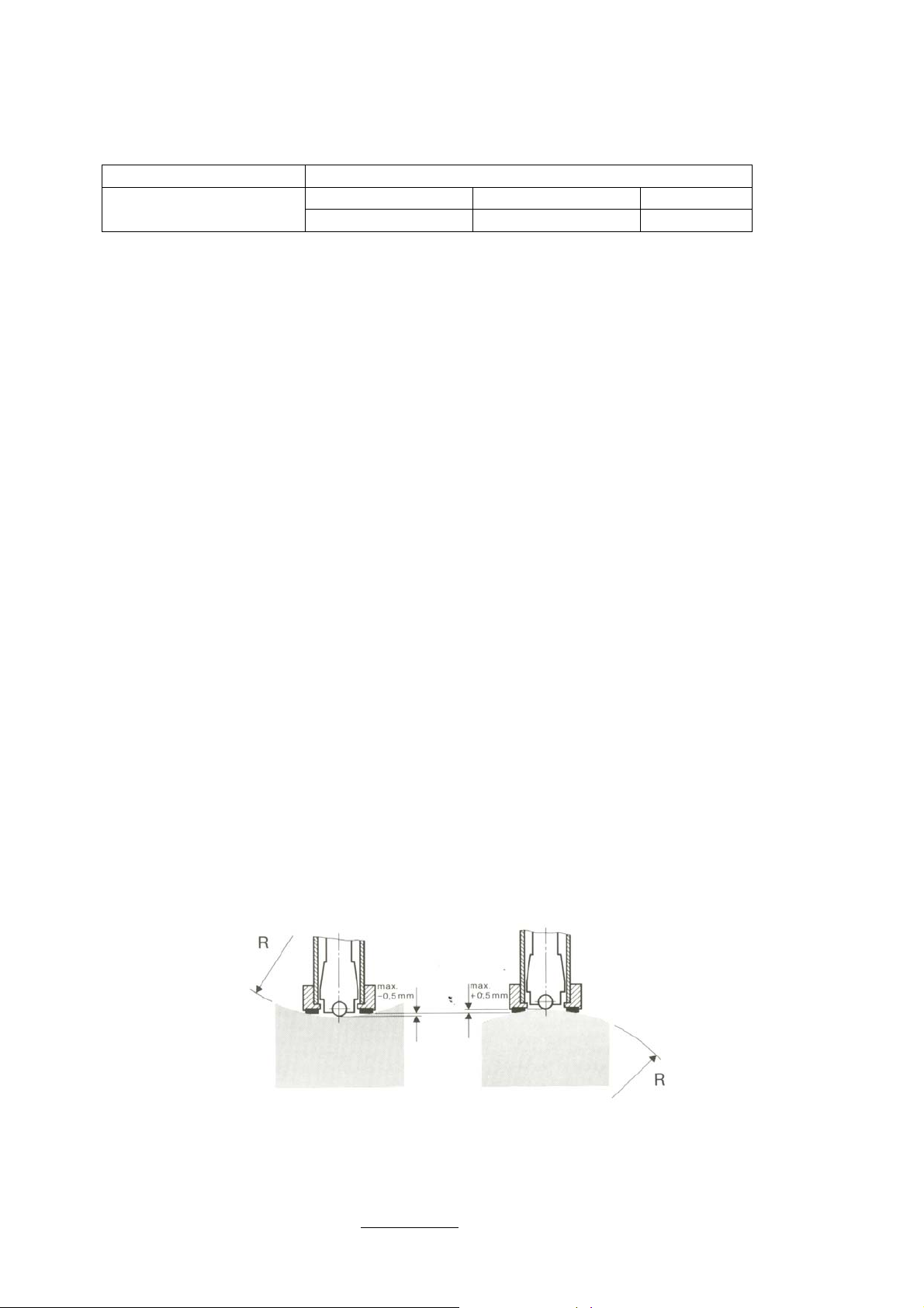
5.7 Samples With Curved Surfaces
Impact testers only work properly, if the impact body has a certain position in the
guide tube at the moment of impacting the test surface. In the normal position,
automatically present when testing flat and convex-cylindrical samples (such as
round samples), the spherical test tip is located exactly at the end of the guide tube.
However, when testing spherically or cylindrically shaped concave surfaces, the
impact body remains further within the guide tube or protrudes further therefore.
Thus, with such types of curved surfaces, it is to be observed that radii of curvature
do not drop below the values indicated in the following Fig.
Curved surfaces should always be tested with the small support ring.
Impact device types D Rmin=30mm
For impact devices D, special support rings are available to accommodate smaller
radii on convex or concave surface.
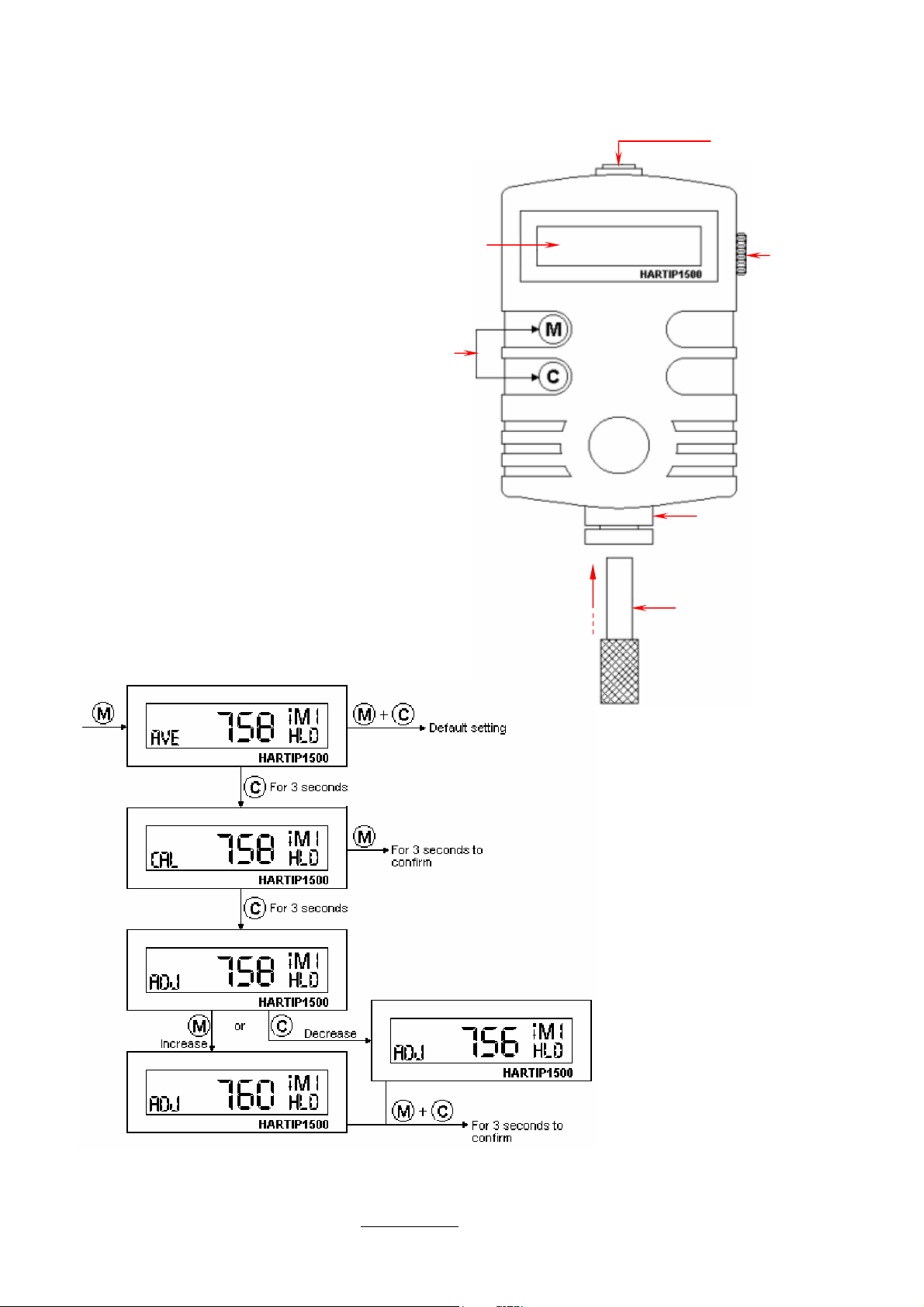
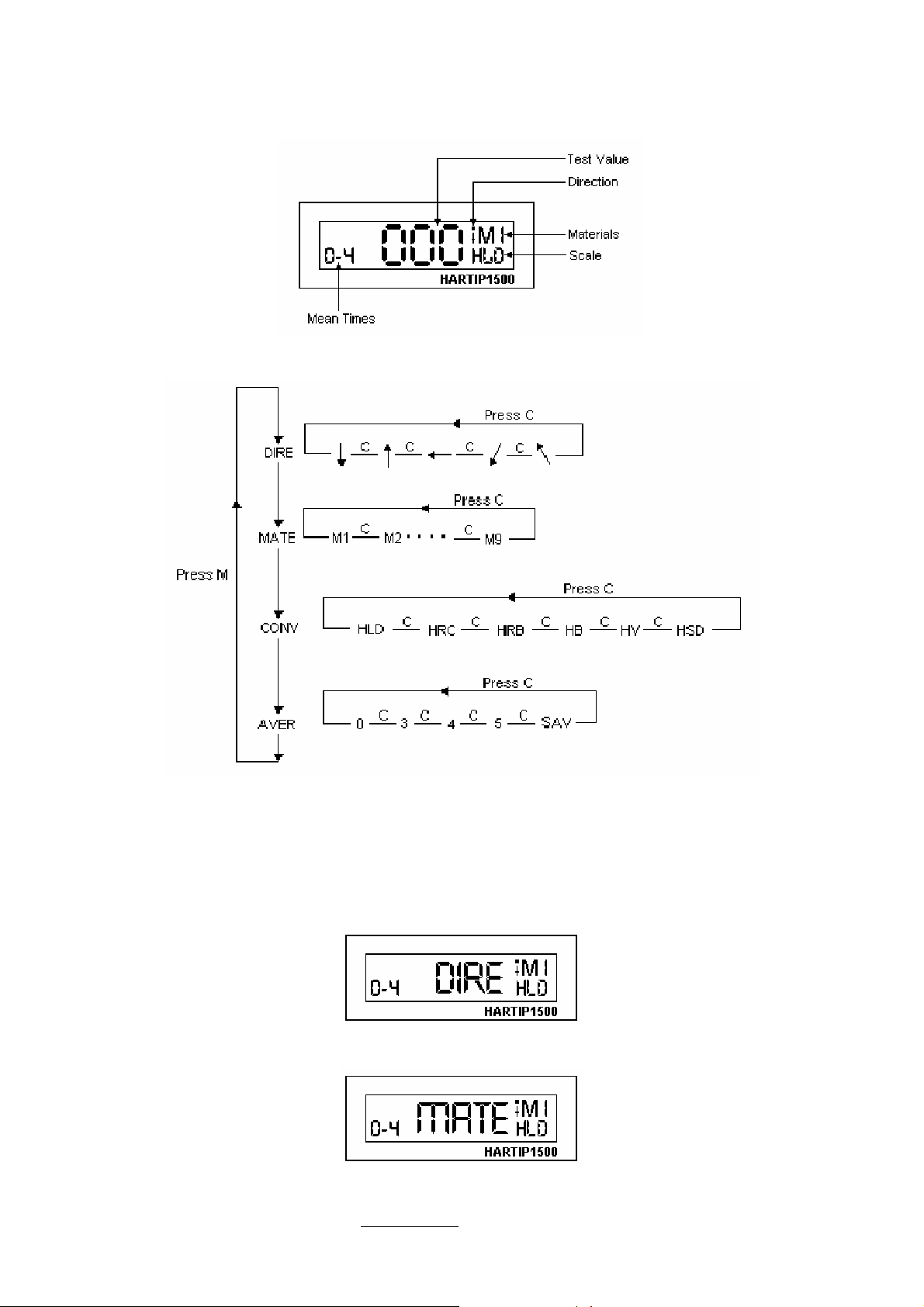
Operation
HARTIP-1500 Manual Rev:00 8 / 14