Cavo system description | 07-2020 Rev. 01 | English | 10
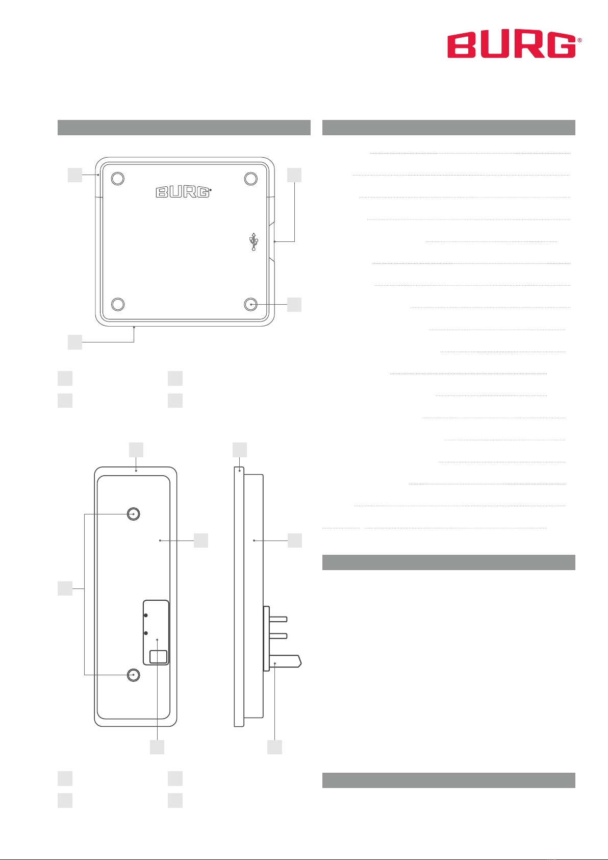
Mount the Cavo System
For setting up a locker system, the locks need to be mounted
on the inside of the cabinets. The door units will be mounted
on the inside of the doors and the door modules (when needed)
are placed on the outside of the doors. The Hubs are placed out-
side, mostly on top of the lockers. The locks and Hubs have to
be connected through a UTP CAT-4 ( ethernet cable) or higher.
We only use the RJ-45 connector as found on standard ether-
net cables.
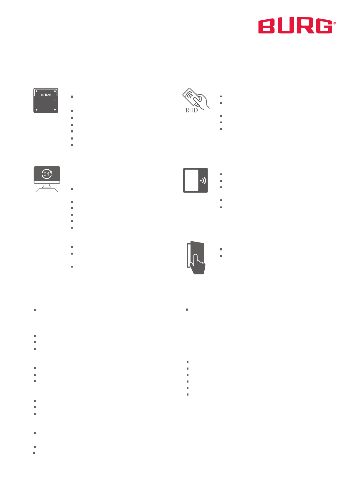
Place the Hubs
Each Hub can accommodate up to 18 locks in the three 6-lock
segments. Please note that the terminal requires one slot. Each
Hub needs to be powered by the supplied 230V power adapter.
To supply several Hubs with power, Y-cables will be required.
The first power supply is connected to 230 V by an inrush cur-
rent limiter. For countries with other voltages, a country-specific
power adapter will be required.
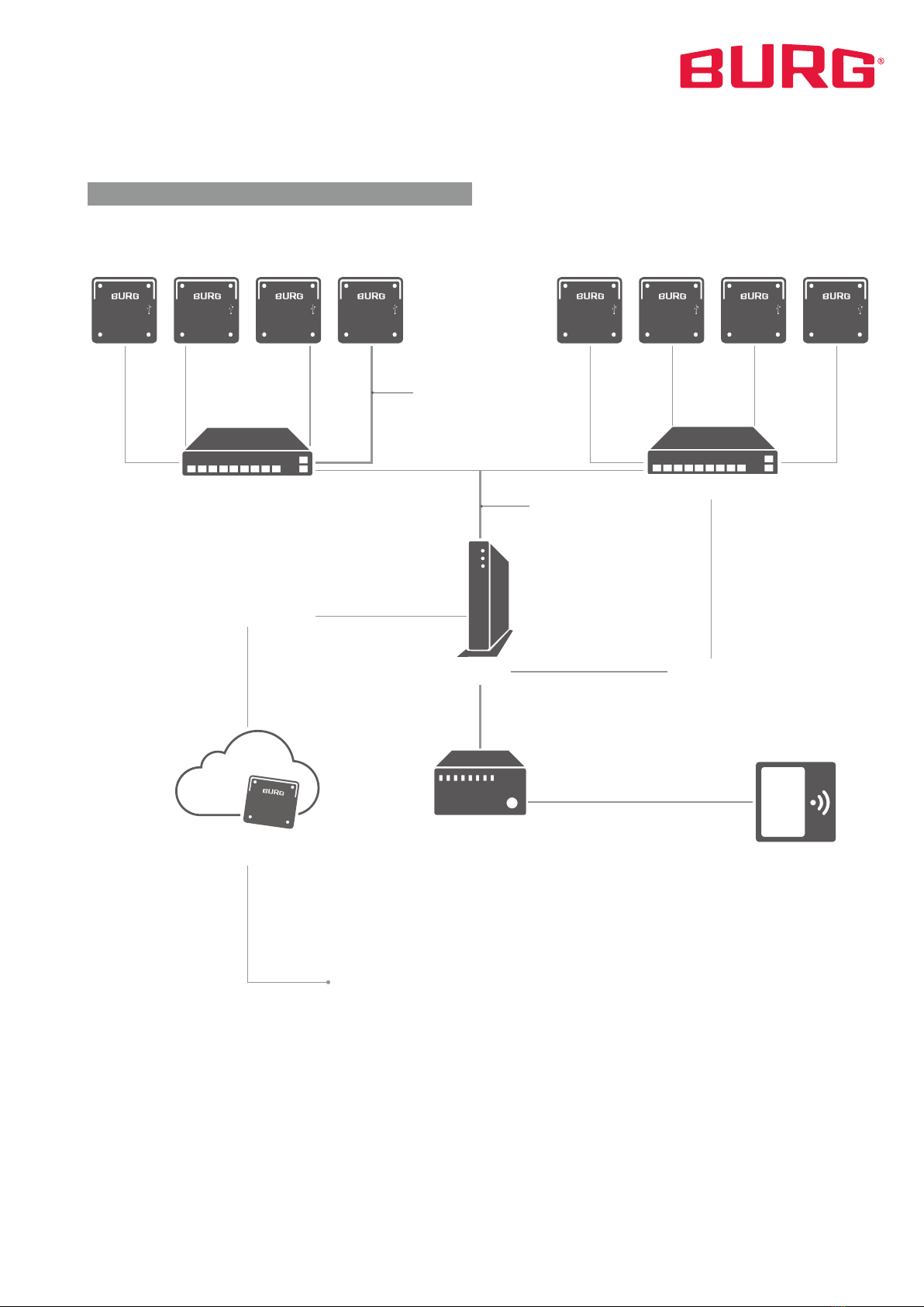
The Hubs can be connected to the router using one of the two
separate ethernet ports. These two ethernet ports, separate
from the 3x6 connectors, can be used either to connect to anot-
her Hub or to connect to the router. The two ethernet ports will
function like a 2-port switch.
Connect Hubs, Router and Controller
After all the locks are connected to the Hubs and all the Hubs
are linked (data and 230V), the first Hub is connected to the
router with an ethernet cable. The power supply of the first Hub
can be placed in the inrush current limiter which can be placed
in a 230 V socket. Now, the controller (NUC) can be connected
to the router. If a terminal is required, just connect the USB cable
for the terminal touchscreen to any port of the locker controller.
Starting the Locker Controller
Once the locker controller has been started, allow it boot. The
start-up can take up to 2 minutes. If nothing happens after 5
minutes have passed, please check all connections.
The appendix contains an overview of all components and the
schematics of the required connections.
Set up the Cavo Dashboard Once the external port on the router is configured to match
the network infrastructure, it is assigned a separate IP address.
The controller can be accessed by accessing the IP address.
Thus, when connected to the internal network, the IP address
is 192.168.1.200; when connected via the hardware, the IP
address is provided by the respective IT department.
To access the dashboard, open any browser - preferably Firefox
or Chrome - and go to the assigned IP address. Via the login
window you can log in with your username and password (pro-
vided by BURG when you purchase the system):
Access to the Cavo Dashboard
After logging in, the start page of the dashboard opens. From
there you have access to the individual settings menus and
statistics. Click on an icon or the menu items in the upper left
corner to get to the respective menu. The person icon takes
you to the user profile, where you can make general settings or
change your password.
Dashboard Basics
Logout and password change
You can log out using the „Logout“ icon on the start page or in
the user profile. To change your password, open the user profile
and click on „Profile“. Enter your desired password in the corre-
sponding input fields.
Menu User profile
By default, the locker management software is accessed via a
web interface. The main IP adress will be:
Main IP address 192.168.1.200
The router is connected to the hardware with a switch that sup-
plies a V-LAN. The default IP address is available on the control-
ler side of the router.
LOCKERS
REPORTING
USERS USAGE
LOGOUT
Skip
Password
Login