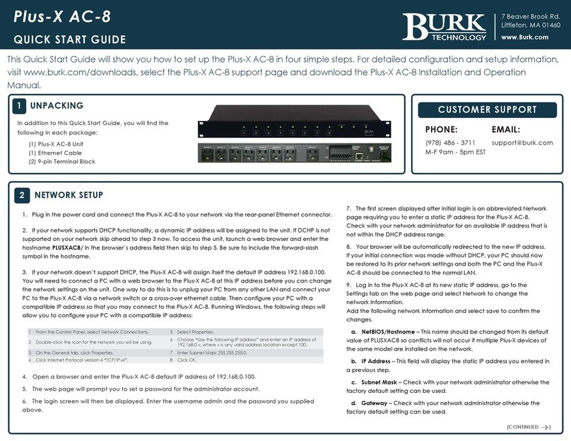
BURK Technology Plus-X AC-8 User manual

Plus-X AC-8
User Guide

Copyright © 2012 Burk Technology, Inc.
Rev. D
Table of Contents
Introduction................................................................................................................................ 1
Network Requirements............................................................................................................... 1
Surge Protection........................................................................................................................ 1
Setup and Configuration ............................................................................................................ 1
Initial Connection Using DHCP .................................................................................................. 1
Initial Connection Without DHCP ............................................................................................... 2
Set a Static IP Address.............................................................................................................. 3
Operation................................................................................................................................... 6
Getting Help............................................................................................................................... 8
Warranty.................................................................................................................................... 8
Appendix A: Specifications......................................................................................................... 9

Plus-X AC-8 User Guide Rev D
1
Introduction
The Plus-X AC-8 Remote Outlet controller manages power to 120V equipment at remote
locations. The unit may be operated via the Burk Technology ARC Plus, AutoPilot® Plus
software, stand-alone web server, or via contact closures from any source (including the Burk
Technology ARC-16, GSC3000 and VRC2500).
Network Requirements
A static IP address is required for initial configuration and for controlling outlets using the
onboard web server. If IP connectivity is not available at the remote site, it is possible to
configure the unit on the bench and operate it via contact closures from a remote control.
Surge Protection
Each of 8 outlets is rated to 15A. Total load for the entire unit is 15A, with circuit-breaker
protection. The rear panel RESET button resets the circuit breaker.
Setup and Configuration
Configuration of the Plus-X AC-8 involves three steps: setting the network parameters, defining
outlet behavior, and assigning users and passwords.
If you are using the Plus-X AC-8 with an ARC Plus, you will also need to add the Plus-X AC-8
device to the ARC Plus using AutoLoad Plus software.
Before you start, you will need to use a standard Cat5 cable (included) to connect the Plus-X AC-
8 to your network.
Initial Connection Using DHCP
Plus-X AC-8 units running firmware 1.0.16 or higher support Dynamic Host Configuration
Protocol (DHCP) as an easy way to do initial setup. Connect the Plus-X AC-8 to your LAN and
apply power. If this is the first power-up for a new unit or the first network connection after
execution of a master-initialization, the Plus-X AC-8 will issue a DHCP request for an IP

Plus-X AC-8 User Guide Rev D
2
address. If the network supports DHCP functionality, a dynamic IP address will be assigned to
the unit. To access the Plus-X AC-8, launch a web browser and enter the hostname
“PLUSXAC8/” in the browser’s address field. (Be sure to include the forward-slash symbol at the
end of the hostname.)
Note: If the login page is not displayed or the browser indicates that the page cannot be found, it is
possible the connected network does not support DHCP. In this case follow the steps outlined below
for “Initial Connection Without DHCP”. Otherwise, continue to “Set a Static IP Address”.
Initial Connection Without DHCP
If your network does not support the DHCP protocol, the Plus-X AC-8’s request for a dynamic IP
address will fail. If this happens, the Plus-X AC-8 will assign itself the default static IP address of
192.168.0.100. To access the unit, it will be necessary to connect your PC directly to the Plus-X
AC-8 using a crossover LAN cable or using a simple Ethernet switch.
In addition, your PC’s internal network interface must be set to a static IP address of the form
192.168.0.x. In the Windows Control Panel, search for Network Connections, then select View
network connections then Local Area Connection. Navigate to the Internet Protocol Version 4
(TCP/IPv4) Properties dialog box as displayed below.
To configure the Plus-X AC-8, start by logging in to the unit by entering the IP address in your
web browser and entering the username and password. The default IP address is
192.168.0.100. The default username is admin and the default password is password.

Plus-X AC-8 User Guide Rev D
3
Set a Static IP Address
Select the Network menu option to display this page showing the current IP address.
Enter a static IP address for this unit as assigned by your network administrator in the IP
Address box and click Save.
Note: It is important that the assigned static IP address be outside the DHCP address range used
by the router to avoid potential conflicts with other DHCP devices.
If your initial connection was made without DHCP, your PC should now be restored to its prior
network settings, and both the PC and the Plus-X AC-8 should be connected to the normal LAN.
Network Configuration
Click the Network link toward the top of the page to establish network settings. Enter the IP
address, subnet, gateway and HTTP port for the Plus-X AC-8 to use. It is also a good idea to
change the hostname from the default value so conflicts will not occur if multiple Plus-X AC-8
units are installed on the network.
If you are using the Plus-X AC-8 in conjunction with an ARC Plus remote control, also enter the
Plus-X port (the default port of 45000 is appropriate in most cases) and the IP address of the
parent ARC Plus. These settings enable the ARC Plus
to view and control the Plus-X AC-8 control channels.
The Plus-X AC-8 can also operate in stand-alone mode
without an ARC Plus. When in stand-alone mode you
can uncheck the “Reinitialize if ARC Plus is not
connected” setting. This will prevent the Plus-X AC-8
from trying to re-initialize communications with the ARC
Plus.
The ARC Plus link indicator at the bottom of the page
indicates whether the Plus-X AC-8 is connected to an
ARC Plus.
If an ARC Plus is not installed, set the ARC Plus IP
Address field to “127.0.0.1”.
Press Update Settings to save your changes. After
changing the network configuration, the Plus-X AC-8
will redirect the web browser to the new network address.

Plus-X AC-8 User Guide Rev D
4
Outlet Configuration
To configure the unit name and individual outlet behavior, click the Config link toward the top of
the page.
In the Name field below the navigation links, enter an
identifier for the Plus-X AC-8 unit (i.e. IT Gear).
Press Update Unit Name to save changes. Each
outlet can also be assigned a name to identify the
equipment connected to it.
Next, configure the pulse/latching behavior and
control input behavior for each outlet. All fields for
each outlet must be configured and saved before
going on to the next outlet.
In the Type field, choose whether a command
originating from the front panel, ARC Plus or web
browser results in the outlet pulsing on/off or latching
on/off.
Pulse On means the outlet will turn on for the specified duration before automatically
turning off. This can be used to periodically cycle equipment on, such as a cooling fan.
Pulse Off means the outlet will turn off and automatically turn back on after the specified
duration. This is useful for rebooting or power-cycling equipment.
Latching means the outlet will turn on until the outlet is manually turned back off (or vice
versa).
The Control Input field determines how the outlet responds to contact closures received from
external equipment, such as a remote control. The outlet will either match the duration of the
contact closure or will use the behavior already configured in the Type field.
For example, if an external remote control relay is connected to the ON control input for Outlet 1
and the outlet is configured to match closure duration, a five-second pulse from the remote
control results in the outlet turning on for five seconds before turning off.
If the outlet is configured for use outlet configuration, the same five-second pulse from the
remote control will result in the outlet pulsing on, pulsing off, or latching, depending on how the
outlet is configured in the Type field.
When you are done configuring the first outlet, press Update Outlet 1 to save changes. Then
continue to configure additional outlets, one at a time.

Plus-X AC-8 User Guide Rev D
5
Users and Passwords
The Plus-X AC-8 allows for 2 users, with up to 10 simultaneous client connections.
To edit users, click the Users link near the top of the
page. Change username and passwords as desired.
The non-admin user is also assigned a privilege level.
The admin user is always a system-level user, with
access to configuration settings (in addition to outlet
control).
The additional user may be assigned system, operator,
or observer privileges:
•Operators can control outlets, but may not modify
configuration settings.
•Observers can view outlet status only (no
configuration or outlet control).
Configure each user individually and press the Update
Password or Update User button after making the
changes.
Adding Plus-X AC-8 Channels to the ARC Plus
The Plus-X AC-8 integrates easily with the Burk Technology ARC Plus remote control system.
Once configured, the ARC Plus will read Plus-X AC-8 status and command channels as if these
channels were native to the ARC Plus unit.
To get started, set up and configure the ARC Plus first. Then return to add Plus-X AC-8
channels:
1. Open AutoLoad Plus and connect to the ARC Plus site where the Plus-X AC-8 will be
added.
2. From the Edit menu, select Plus-X Devices to open the Plus-X device configuration
dialog.
3. Click New…
4. You will be asked to select the device type, which in this case is “Plus-X AC-8” You may
optionally change the Description for the device. The description appears in AutoLoad
Plus to identify each Plus-X channel.
5. Enter the IP address and port number of the Plus-X AC-8. These should be the same
settings you used when you configured the Plus-X AC-8 via its built-in web server.
6. Check the Map default set of channels box to automatically add eight status and eight
command channels to the ARC Plus. Where prompted, enter the number of the first
unused ARC Plus channel you wish to assign to the Plus-X AC-8. There must be eight
consecutive, unused channels available, starting with the channel number you enter
here. You do not need to have additional Integrated Input Units and Integrated
Command Relay Units for these channels.

Plus-X AC-8 User Guide Rev D
6
Important! Plus-X channels take the place of normal I/O channels. If a metering input, status
input, or command relay is connected to an ARC Plus channel and a Plus-X parameter is
subsequently mapped to that channel, the I/O channel will no longer be displayed.
7. Click OK.
Restoring Default Configuration
If at any time you wish to restore the default configuration of the Plus-X AC-8, including the IP
address, use a pen or other small object to press the rear panel Master Init button three times
in 10 seconds. (The button on some units may be labeled Config). The power LED blinks to
confirm the configuration has been reset.
Disabling Rear Panel Control Inputs and/or Front Panel Control
The front panel pushbutton controls and the rear
panel control inputs can be disabled by
disengaging jumpers at J15 and J14. To locate
these jumpers, disconnect power from the Plus-X
AC-8 and remove the top cover. The jumpers are
located near the bottom right corner of the board,
directly above the Burk Technology logo.
Rear panel control inputs are enabled when the J15 jumper is engaged (connected to both pins)
and disabled when the jumper is removed or connected to only one pin.
Front panel pushbutton control is enabled when the J14 jumper is engaged (connected to both
pins) and disabled when the jumper is removed or connected to only one pin.
Rear Panel Outlet Connections
Site equipment connects to the rear panel 120V outlets as it would to any wall outlet or power
strip. Outlet 1 is offset to accommodate AC/DC wall adapters. To connect additional wall
adapters to the remaining outlets, Burk Technology recommends using 12” extension cords
designed for this purpose.
Operation
Outlet control is accomplished via any of four methods: front panel pushbuttons, ARC
Plus/AutoPilot Plus connectivity, onboard web server, and/or external contract closure signaling.
Pushbutton Actuation
The front panel pushbuttons provide local outlet control with LED indication of whether the outlet
is currently powered. Commands issued via pushbutton follow the outlet behavior settings set
up during configuration (pulse on, pulse off or latching).

Plus-X AC-8 User Guide Rev D
7
Control via Web Server
Logging in to the web server, just as you did to configure the unit, provides web-based access
to all eight outlets. Click the Outlets link to access outlet control.
The HTML interface supports Internet Explorer and the
following mobile web platforms: Apple iPhone, Palm
OS, Windows Mobile, Windows Mobile PC, and
BlackBerry. Other browsers may work, but factory
support is limited to those listed here.
Control via ARC Plus and/or AutoPilot®Plus software
Once the Plus-X AC-8 channels have been added to the ARC Plus, they are available for
control using the ARC Plus front panel, web interface, AutoPilot Plus software and ESI Plus
telephone interface, just as if these channels were native to the ARC Plus.
You can also incorporate Plus-X AC-8 channels in ARC Plus macros to allow more complex
control of the connected equipment. For example, an ARC Plus macro can remove power from
non-critical equipment if the remote site is on generator power.
Control via Contact Closures
To connect an external remote control, such as the Burk ARC-16, GSC3000 or VRC2500 to the
Plus-X AC-8, simply connect a pair of command relays from the remote control to the rear panel
control input associated with the desired outlet. Typically “raise” relays would connect to the ON
pins on the Plus-X AC-8 and “lower” relays would connect to the OFF pins on the Plus-X AC-8.
A common ground pin is provided. Wiring is to the included screw-down Phoenix connector.
Commands issued via external control input can either follow the relay duration or match the
pre-programmed outlet configuration. For details, see “Outlet Configuration” under Setup and
Configuration.

Plus-X AC-8 User Guide Rev D
8
Uploading Firmware
To upload firmware to the Plus-X AC-8 go to www.burk.com/downloads and select the Burk
Firmware Loader support page. Download the Burk Firmware Loader Manual and follow the
instructions outlined to update your Plus-X AC-8 firmware.
Getting Help
For technical support, please email suppo[email protected]m or call our direct technical support line at
978-486-3711. We will be glad to assist you. The technical support office is open Monday –
Friday, 9AM to 5PM Eastern time.
Warranty
Burk Technology, Inc. warrants the Plus-X 600 to be free of defects in materials and
workmanship for a period of 24 months from the date of purchase. Equipment will be repaired or
replaced at the option of Burk Technology and returned freight prepaid to the customer.
Damage due to abuse or improper operation or installation of the equipment or caused by fire or
flood or harsh environment is not to be covered by this warranty. Damage in shipping is not the
responsibility of Burk Technology. A return authorization must be obtained before returning any
equipment. Materials returned under this warranty must be shipped freight prepaid and insured
in the original shipping carton or suitable substitute to Burk Technology, Inc., 7 Beaver Brook
Road, Littleton, MA 01460. Repairs not covered under this warranty will be made at prevailing
shop rates established by Burk Technology.
THE WARRANTY SET FORTH ABOVE IS IN LIEU OF ALL OTHER WARRANTIES, EXPRESS
OR IMPLIED, INCLUDING BUT NOT LIMITED TO THE WARRANTIES OF
MERCHANTABILITY AND FITNESS FOR A PARTICULAR PURPOSE. BURK TECHNOLOGY,
INC. SHALL NOT BE LIABLE TO ANY PARTY FOR ANY INCIDENTAL, SPECIAL, INDIRECT
OR CONSEQUENTIAL DAMAGES ARISING FROM THE USE OF THIS EQUIPMENT.

Plus-X AC-8 User Guide Rev D
9
Appendix A: Specifications
Dimensions:
1.75” (4.45cm) H
19”(48.26cm) W
10” (25.4cm) D
Operating Temperature:
0oto 50oC
Power Requirements:
100 to 132VAC, 50-60Hz, 8’ attached 14/13 grounded power cord; 15A circuit breaker with reset
button
Outlet Specifications:
Eight (8) 15A straight-blade AC outlets; latching, plus-on or plus-off configuration for each outlet
Control Inputs:
>0 to 5VDC or switch closure; latching relays not required
Other manuals for Plus-X AC-8
1
Table of contents
Other BURK Technology Controllers manuals