manuals.online logo
Brands
  1. Home
  2. •
  3. Brands
  4. •
  5. BURK Technology
  6. •
  7. Recording Equipment
  8. •
  9. BURK Technology TS-1 User manual

BURK Technology TS-1 User manual

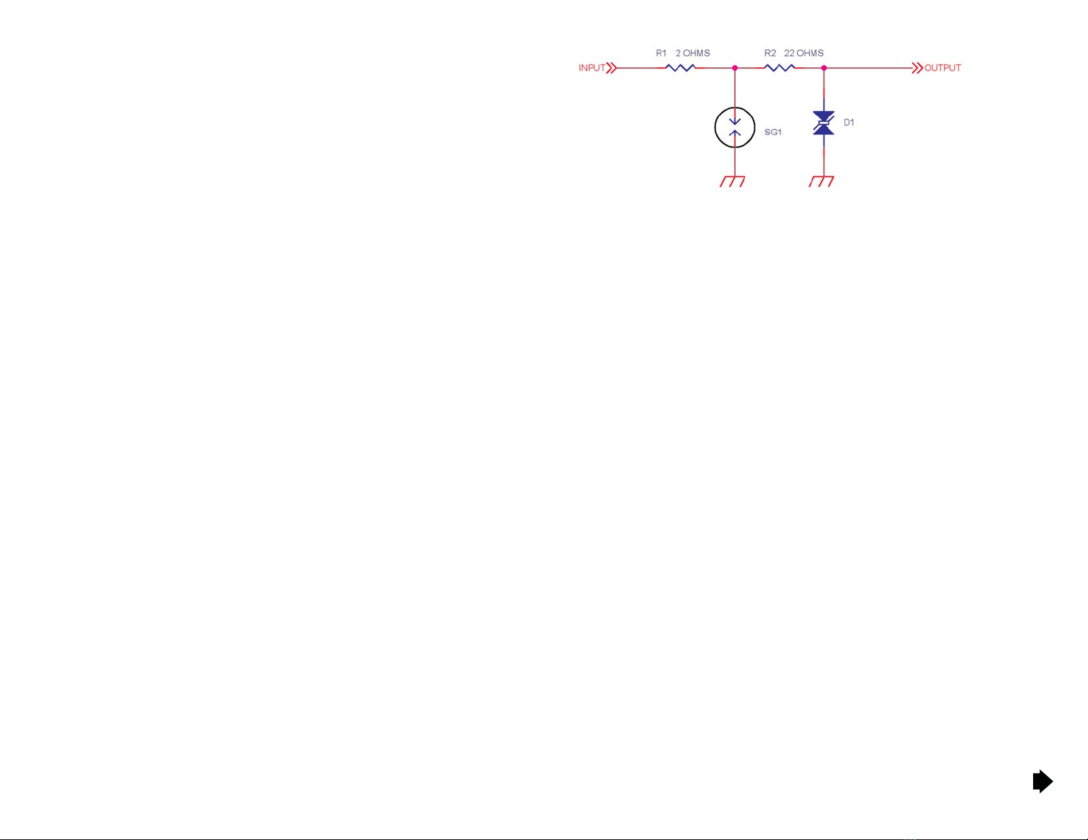
The TS-1 Dial Line Transient Suppressor provides transient voltage surge suppression for
equipment connected to a dial telephone line with standard RJ-13 or RJ-11 connectors.
The high quality die cast aluminum enclosure houses a passive, three-stage protection
device designed to conduct destructive energy safely to ground.
Both pairs in the RJ-13 standard configuration are afforded protection, while allowing the
normal ring voltage, and voice or data to pass unimpeded. Studio or transmitter audio
equipment connected to a two-pair dedicated stereo telco circuit may also be protected
with the TS-1.
The TS-1 must be connected to an adequate station ground to provide a path for
destructive energy to be shunted away from the protected equipment. Ideally, the TS-1
should be mounted on the copper strap directly connected to station ground. The integral
clamping system on the TS-1 affords easy mounting on strap up to four inches wide and
ensures a low-impedance path to ground. Alternatively, the TS-1 may be connected to earth
ground using the ground lug on the side of the enclosure.
INSTALLATION
Position the TS-1 near the telco service entry. In the event of a catastrophic lightning strike
to the phone line, this location prevents destructive energy from entering the facility.
Installation of the TS-1 is straightforward:
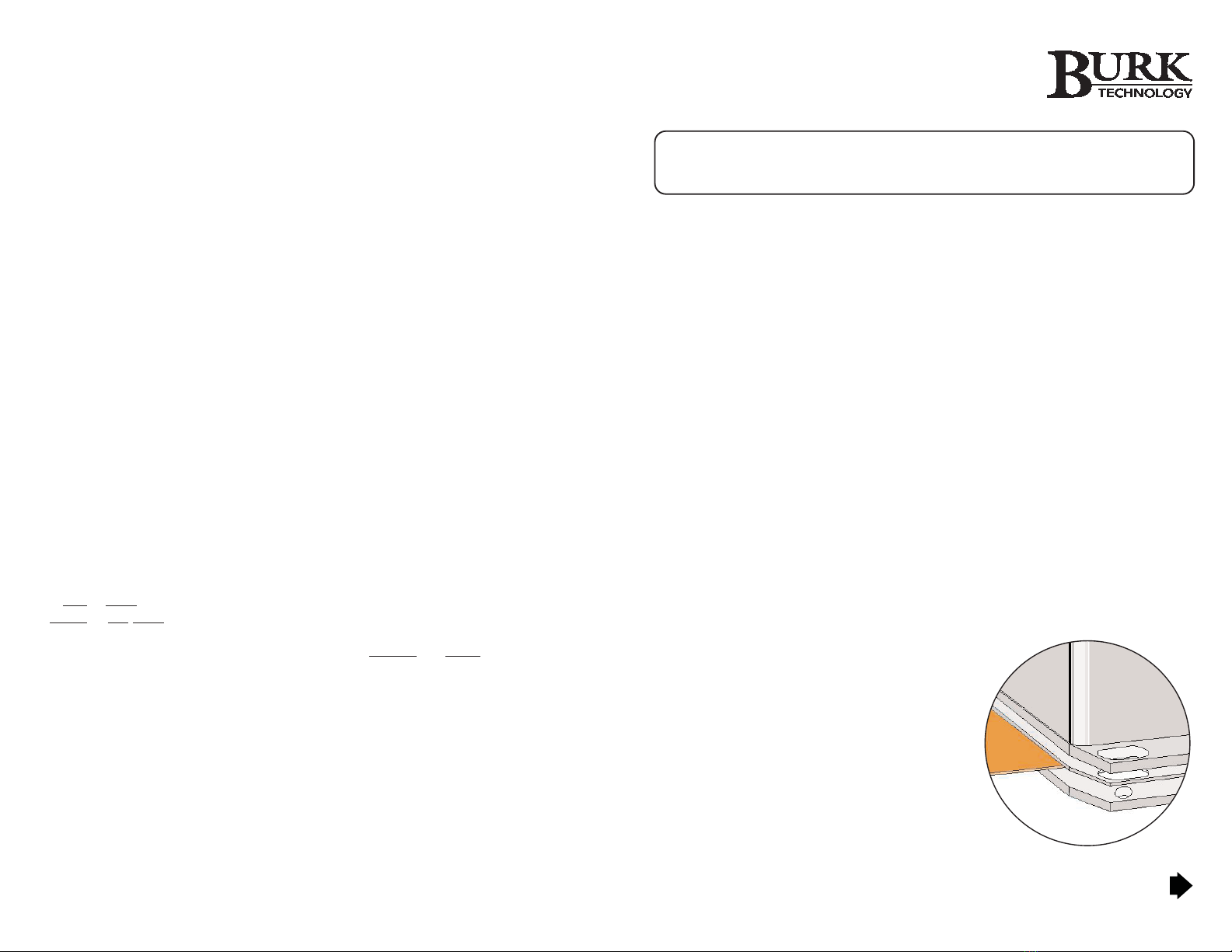
1. The preferred mounting scheme is to secure the
TS-1 to the station ground bus. First, remove the
machine screws from the TS-1. Beneath the
aluminum enclosure, you will find a thin
stainless steel shim on top of the stainless
steel backing plate. Clamp the ground bus
between the backing plate and shim, as
illustrated. Then attach the aluminum
enclosure so that it is flush with the stainless
steel shim and not touching the ground bus.
Secure the TS-1 by tightening the machine
screws (Phillips #8 x ½”).
TS-1 Dial Line
Transient
Suppressor
WARRANTY
Burk Technology, Inc. warrants the TS-1 Transient Voltage Surge Suppressor to be free of
defects in materials and workmanship for a period of 24 months from the date of purchase.
Equipment will be repaired or replaced at the option of Burk Technology and returned
freight prepaid to the customer. Damage due to abuse or improper operation or installation
of the equipment or caused by fire or flood or harsh environment is not to be covered by
this warranty. Damage in shipping is not the responsibility of Burk Technology. A return
authorization must be obtained before returning any equipment. Materials returned under
this warranty must be shipped freight prepaid and insured in the original shipping carton or
suitable substitute to Burk Technology, 7 Beaver Brook Road, Littleton, MA 01460. Repairs
not covered under this warranty will be made at prevailing shop rates established by Burk
Technology, Inc.
THE WARRANTY SET FORTH ABOVE IS IN LIEU OF ALL OTHER WARRANTIES,
EXPRESS OR IMPLIED, INCLUDING BUT NOT LIMITED TO THE WARRANTIES OF
MERCHANTABILITY AND FITNESS FOR A PARTICULAR PURPOSE. BURK
TECHNOLOGY, INC. SHALL NOT BE LIABLE TO ANY PARTY FOR ANY INCIDENTAL,
SPECIAL, INDIRECT OR CONSEQUENTIAL DAMAGES ARISING FROM THE USE OF
THIS EQUIPMENT.
GETTING HELP
The Burk TS-1 is designed to protect indefinitely against multiple surges. If a catastrophic
strike disables the TS-1, the device breaks the line circuit so there is no loss of protection.
Therefore, if an otherwise functional telephone line is inoperative when connected to the
TS-1, the unit may need factory repair.
For assistance with the TS-1, please contact Burk Technology customer support:
Phone: 978-486-3711
Web: www.burk.com
Email: support@burk.com
Contact the sales department toll free at 800-255-8090, or email sales@burk.com.
TS-1 USER GUIDE, REV D
Copyright © 2015 Burk Technology, Inc. All rights reserved. No part of this manual may be reproduced in any form
or by any means without written permission from Burk Technology. Information in this manual is subject to change
without notice.
User Guide
The TS-1 is equipped with a grounding lug for use when a station ground bus is not
available. To use the grounding lug, loosen the wing nut and wrap a short, heavy braid
clockwise around the grounding lug between the two flat washers. Then tighten the wing
nut to firmly secure the braid. Connect the opposite end of the braid to a ground rod driven
at least six feet into the earth. Four #10 x ¾" self-tapping screws are included for mounting
the TS-1.
Important! Do not connect the TS-1 to any water pipe or equipment chassis. It must have a
low-impedance dedicated ground to function properly.
2. Connect the incoming telco line to the UNPROTECTED RJ-13 jack, and connect the
equipment to be protected to the PROTECTED RJ-13 jack. Making the connections
to the proper jacks is critical.
THEORY OF OPERATION
Three-Stage Design
The Burk TS-1 Transient Suppressor employs a three-stage design to shunt destructive
energy to ground, providing superior protection. In the event that catastrophic energy is
introduced into the TS-1 due, for instance, to a direct lightning strike, the TS-1 is designed
to open circuit and protect the user equipment.
• The first line of protection is provided by a gas discharge tube (GDT), which will
ionize in less than a microsecond if a severe transient is induced.
• Next, a high-power wirewound resistor provides both current limiting and inductance
to slow down the rise time of the pulse energy.
• Following the resistor is a high-power transient voltage suppressor (TVS) to conduct
the remaining transient energy to ground. The response time of the TVS is 5
nanoseconds.
This three-stage scheme is the most reliable solution to provide proper protection for user
equipment.
Design Schematic
The following schematic is a representative section of the Burk TS-1. Under normal
transient events, D1 conducts as necessary to limit the voltage at the output. R2 is a wire
wound resistor designed to limit the current into the TVS and to provide inductance for
pulse stretching. SG1 is used to protect from large transients and R1 is a fusible element
used as a last resort protection scheme.
Normally, the gas discharge tube (GDT) does not fire unless a transient over 350 volts is
encountered. This action will preserve the useful life of the GDT.
Standards Testing
Burk Technology has conducted extensive standards testing at an approved agency to
verify the failure modes of the TS-1. Using the standard 1.2x50uS test waveform specified
in EN6100-4-5, the device repeatedly handles 3-kilovolt discharges and maintains the
specified limit of 300 volts peak at the output. As the discharge voltage is raised, the GDT
comes on to protect the downstream circuitry and no degradation is seen with discharges
up to 4-kilovolts for 10 discharges. A 10-kilovolt discharge results in R1 fusing and
protecting the user equipment at the expense of the TS-1. Any discharge over 10 kilovolts
results in the destruction of the modular input connector as well as R1.
This testing was conducted for common mode discharges. The Burk TS-1 also incorporates
differential mode transient suppression devices and these results were also shown to limit
the output voltage to 300 volts peak.
SPECIFICATIONS
Dimensions:
5.48” L x 3.24” W x 1.73” H
Bandwidth:
DC to 5 MHz
Maximum repetitive surge current:
2000 amps
Maximum surge current:
10,000 amps
Maximum energy capacity:
500 Joules
Response time:
5 nanoseconds
Standard clamping voltage:
300 volts
Series Impedance:
24 ohms
Maximum series current:
1 amp
Operating Altitude:
10,000 feet
Operating Humidity:
5% to 90% non-condensing
Operating temperature range:
32-185°F

Other BURK Technology Recording Equipment manuals

BURK Technology Plus-X IIU User manual

BURK Technology

BURK Technology Plus-X IIU User manual

BURK Technology LX-1 User manual

BURK Technology

BURK Technology LX-1 User manual

Popular Recording Equipment manuals by other brands

Adcom GSP-560 owner's manual

Adcom

Adcom GSP-560 owner's manual

EPOS UI 770 quick guide

EPOS

EPOS UI 770 quick guide

BOSSCO Loop Station RC-20 owner's manual

BOSSCO

BOSSCO Loop Station RC-20 owner's manual

1010music nanobox razzmatazz quick start guide

1010music

1010music nanobox razzmatazz quick start guide

Byte Delight DivMMC EnJOY! manual

Byte Delight

Byte Delight DivMMC EnJOY! manual

BOSSCO Dr.Sample SP-202 owner's manual

BOSSCO

BOSSCO Dr.Sample SP-202 owner's manual

IMG STAGE LINE DELTA-160 Brief instructions

IMG STAGE LINE

IMG STAGE LINE DELTA-160 Brief instructions

iKonavs SYNERGY AU4 user manual

iKonavs

iKonavs SYNERGY AU4 user manual

ICON Qcon ProX user manual

ICON

ICON Qcon ProX user manual

Medel OPUS 2 Troubleshooting

Medel

Medel OPUS 2 Troubleshooting

Data Video HS-2850 instruction manual

Data Video

Data Video HS-2850 instruction manual

BOSSCO ME-6B owner's manual

BOSSCO

BOSSCO ME-6B owner's manual

BOSSCO GT-6B owner's manual

BOSSCO

BOSSCO GT-6B owner's manual

Multitech ISI4604-PCI quick start guide

Multitech

Multitech ISI4604-PCI quick start guide

Elektron Analog Heat MKII user manual

Elektron

Elektron Analog Heat MKII user manual

BOSSCO JamStation JS-5 owner's manual

BOSSCO

BOSSCO JamStation JS-5 owner's manual

WindowMaster WUF 110 0101 Installation instructions manual

WindowMaster

WindowMaster WUF 110 0101 Installation instructions manual

Data Video HDR-70 Brochure & specs

Data Video

Data Video HDR-70 Brochure & specs

manuals.online logo
manuals.online logoBrands
  • About & Mission
  • Contact us
  • Privacy Policy
  • Terms and Conditions

Copyright 2025 Manuals.Online. All Rights Reserved.