2
1. THE OPERATING INSTRUCTIONS
The operating instructions contain important information.
• Read the instructions carefully and follow the safety instructions in
particular.
• Keep the instructions in a location where they are available to every
user.
• The liability and warranty for the product do not apply if the proce-
dures in the instructions are not observed.
1.1. Symbols
→designates a procedure which you must carry out.
Warning of injuries:
DANGER!
Immediate danger! Serious or fatal injuries.
WARNING!
Possible danger! Serious or fatal injuries.
CAUTION!
Danger! Moderate or minor injuries.
Warning of damage:
NOTE!
2. INTENDED USE
Non-authorized use of the Type BBS-04/-4S may be dangerous
to people, nearby equipment and the environment.
• Type BBS-04/-4S has been designed as a hose/hose coupling for
the flow of gases and liquids in the sterile area.
• Use according to the authorized data, operating conditions, and
conditions of use specified in the contract documents and operat-
ing instructions.
• Correct transportation, storage and installation, as well as care-
ful use and maintenance are essential for reliable and faultless
operation.
• Use the product only as intended.
2.1. Restrictions
If exporting the products, observe any existing restrictions.
2.2. Definitions of terms
The term "product" used in these instructions always refers to hoses/
hose couplings Type BBS-04/-4S.
english
3
4. GENERAL INFORMATION
4.1. Contact address
Germany
Bürkert Fluid Control Systems
Sales Center
Christian-Bürkert-Str. 13-17
D-74653 Ingelfingen
Tel. + 49 (0) 7940 - 10 91 111
Fax + 49 (0) 7940 - 10 91 448
International
Contact addresses can be found on the final pages of the printed
operating instructions. And also on the Internet at: www.burkert.com
4.2. Warranty
The warranty is only valid if the product is used as intended in
accordance with the specified application conditions.
4.3. Information on the Internet
The operating instructions and data sheets for Type BBS-04/-4S can
be found on the Internet at: www.burkert.com
3. BASIC SAFETY INSTRUCTIONS
These safety instructions do not take into account any contingencies and
events which may arise during the installation, operation and maintenance
of the product.
Danger – high pressure and discharge of medium!
• Before loosening the nuts or screws, always turn off the pressure
and relieve the lines/containers.
• Wear protective equipment if media is hazardous.
General hazardous situations
• Do not make any internal or external changes to the product.
• Ensure that the system cannot be activated unintentionally.
• Installation and maintenance work may be carried out only by
authorized technicians with the appropriate tools.
• The product may be operated only when in perfect condition and in
consideration of the operating instructions.
• As far as inspection, maintenance and repairs are concerned,
observe national provisions of the country in which the connection
elements are installed.
• The general rules of technology apply to application planning and
operation of the product.
english
4
5. TECHNICAL DATA
5.1. Conformity
Type BBS-04/-4S conforms to the EC directives according to the
EC Declaration of Conformity.
5.2. Standards (if applicable)
The applied standards which are used to demonstrate compliance with
the EC Directives are listed in the EC type test certificate and/or the
EC Declaration of Conformity.
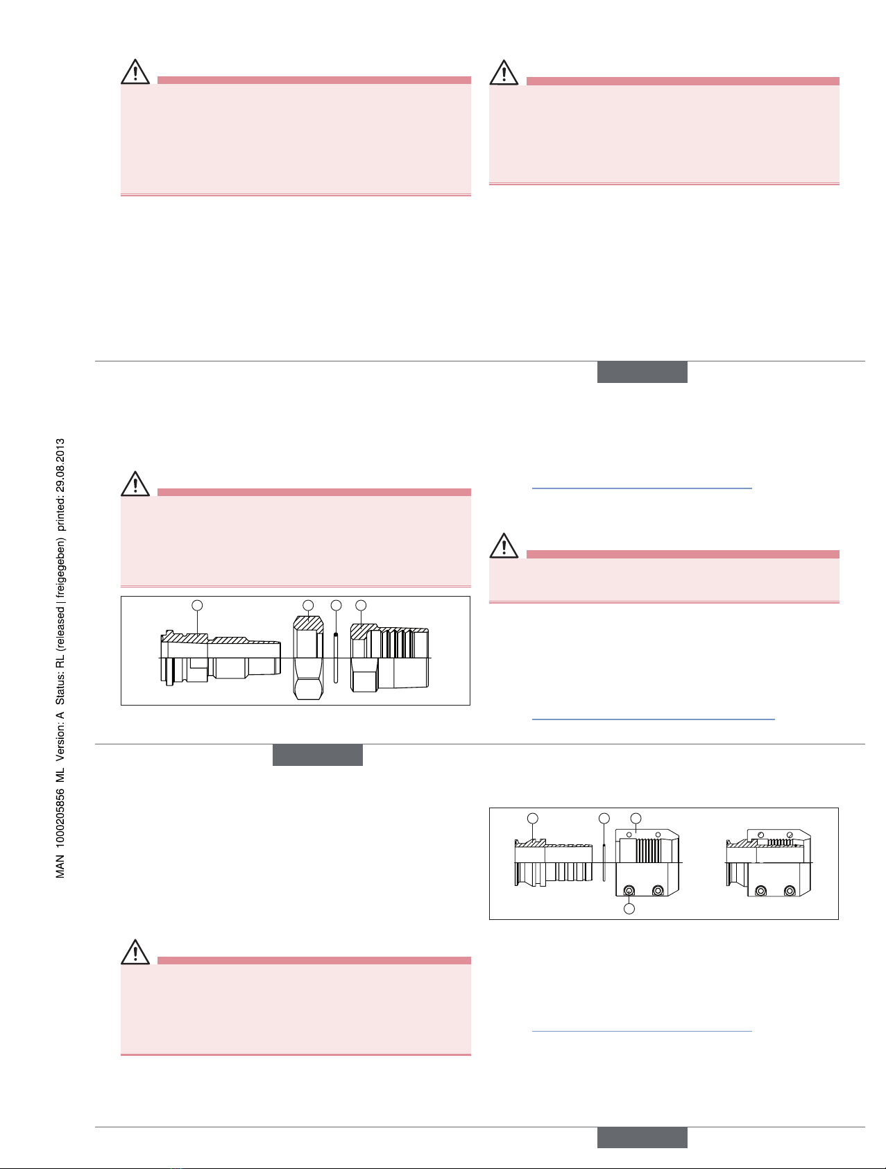
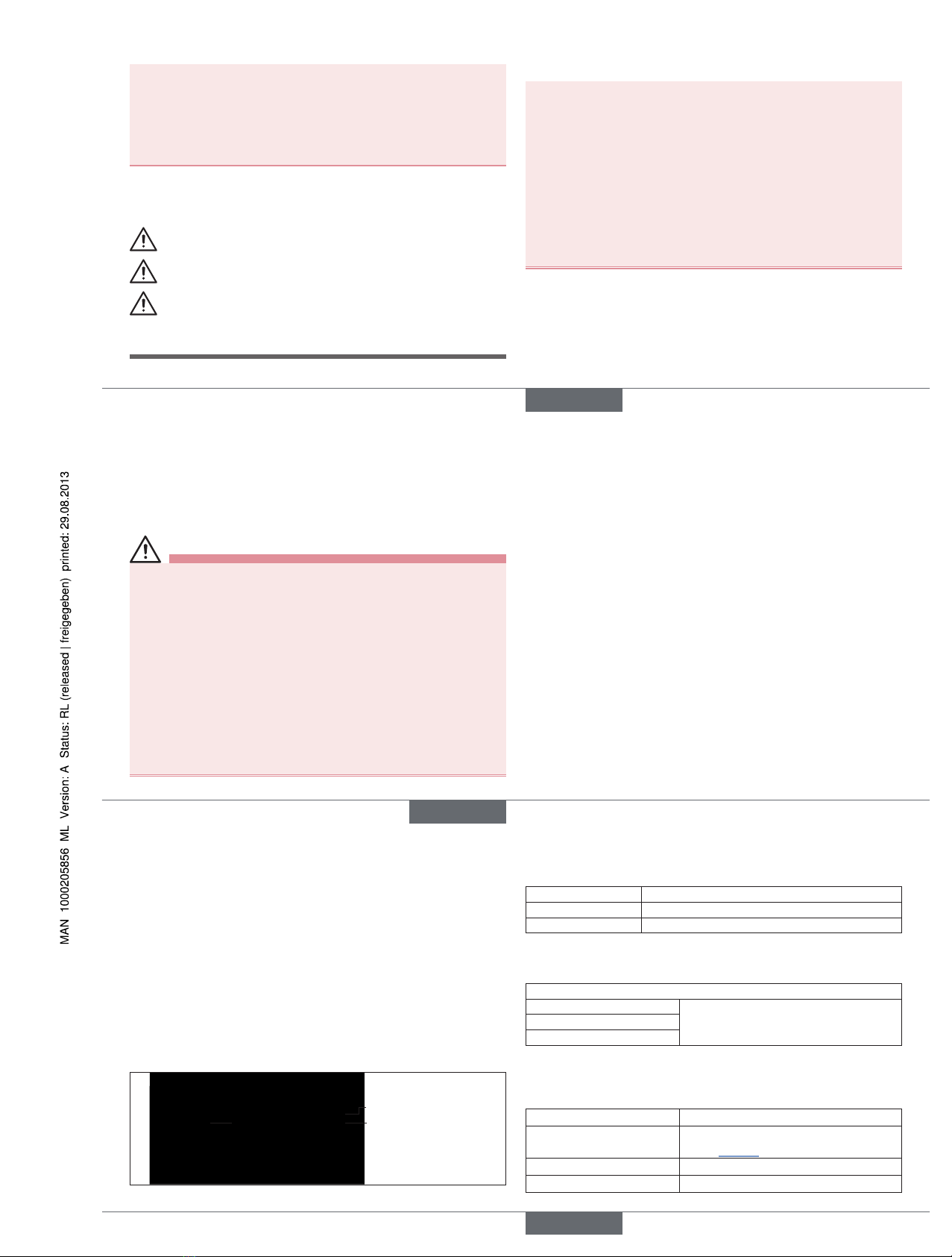
5.3. Identification
Information on material, pipe and connection dimensions can be found
on the stamping on the product. The identification number of the
product can be found on the supplied 3.1 certificate.
Material
Material charge number
Nominal connection
diameter with pipe
standard
Fig. 1: Example of identification of the product
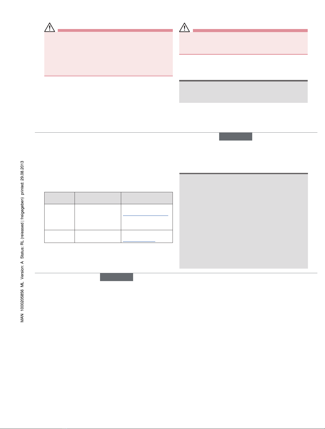
5.4. Sealing materials
Seal material Operating temperature
EPDM –40 °C to 90 °C, briefly up to 140 °C
FEP –60 °C to 160 °C, briefly up to 205 °C
Tab. 1: Sealing materials BBS-04/-4S
5.5. Hose materials
Silicone hoses
Permitted application
temperature see data sheet
BBS-04 Silicone hosesPermitted operating pressure
Minimum bursting pressure
Tab. 2: Hose materials BBS-04
5.6. General technical data coupling
elements
Material Stainless steel 1.4435 BN2 (316L)
Permitted application
temperature depending on sealing and hose
material (see "Tab. 1" or data sheet)
Ambient temperature –20 °C to +80 °C
Media Fluids
english
Type BBS-04/-4S