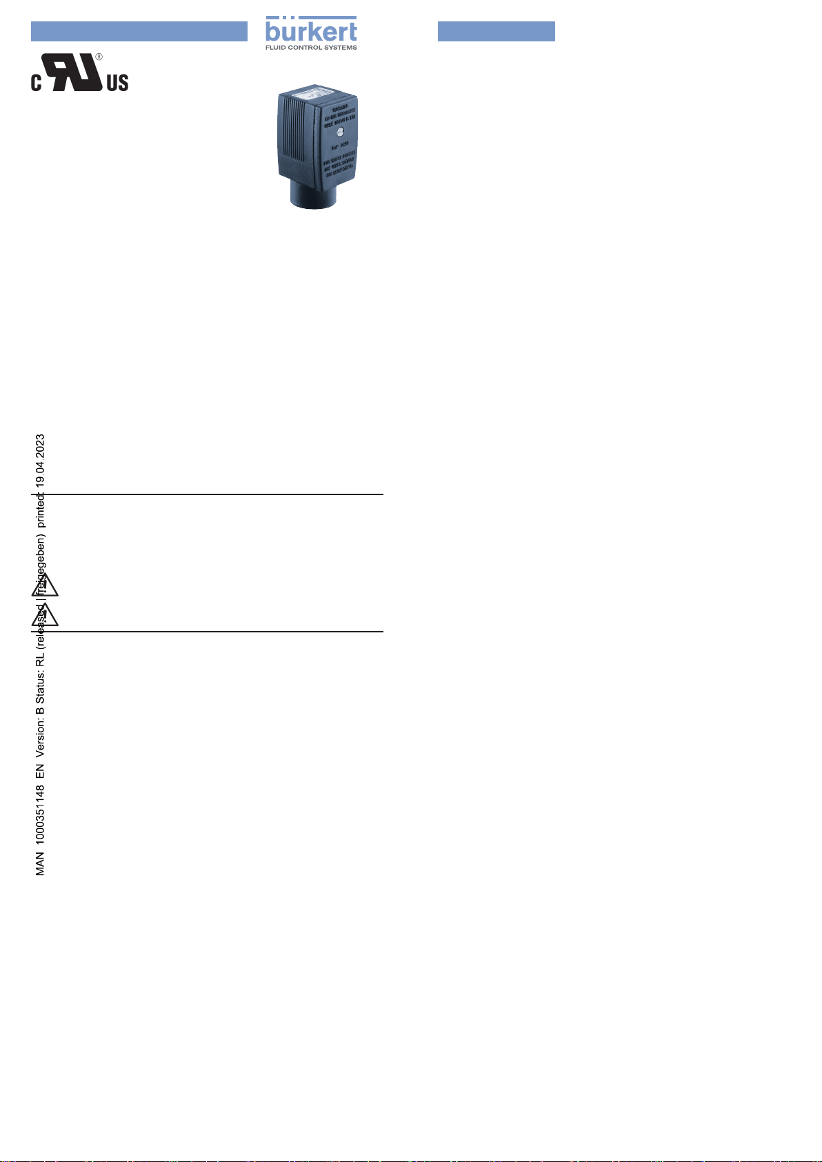
manuals.online logo
Brands
  1. Home
  2. •
  3. Brands
  4. •
  5. Burkert
  6. •
  7. Cables And Connectors
  8. •
  9. Burkert 2509 User manual

Burkert 2509 User manual

english
Type 2509
Cable plug
Conduit Connection, UL approved
Operating Instructions
SYMBOLS
→designates a procedure which you must carry out.
Warning of serious or fatal injuries:
DANGER!
In case of imminent danger.
WARNING!
In case of potential danger.
Address
Germany / Deutschland / Allemagne
Bürkert Fluid Control Systems
Sales Center
Christian-Bürkert-Str. 13-17
D-74653 Ingelngen
Tel. + 49 (0) 7940 - 10-91 111
Fax + 49 (0) 7940 - 10-91 448
E-mail: [email protected]
Manuals and data sheets on the Internet : www.burkert.com
© Bürkert Werke GmbH & Co. KG, 2018-2023
Operating Instructions 2304/01_EN-EN_00810635 / Original DE
1 SYSTEM
DESCRIPTION
1.1 General description
The cable plug Type 2509 with UL certication consists
of a polyamide housing without integrated electronics.
The connector is in accordance with DIN EN 175301-803
(previously DIN 43650 Form A).
1.2 Functions
The cable plug Type 2509 is used for joining conduit con-
nections to solenoid coils.
1.3 Inteded use
This connector is intended for use in ordinary (non-Ex)
locations.
Additionally this connector is intended for use in haz-
ardous (Ex) locations if combination of this connector
with the appropriate coil is declared permitted for use in
hazardous (Ex) locations in the manual of the coil.
2 TECHNICAL DATA
2.1 Conformity
The cable plug Type 2509 conforms to the EU directives
according to the EU Declaration of Conformity (where
applicable).
2.2 Standards
UL 2238 and C22.2 No. 182.3M-1987
The applied standards, which are used to demonstrate
conformity with the EU Directives, are listed in the EU type
test certicate and/or the EU Declaration of Conformity
(where applicable).
2.3 Operating conditions
Certication UL le no. E238288
Self-Declared Operating Conditions
Operating temperature –40 °C...+90 °C
(–40 °F...+194 °F)
Degree of protection NEMA 4X (IP65)
2.4 Mechanical data
Dimensions see data sheet
(approx. 33 x 33 x 59 mm)
Materials
Housing Polyamide
Seal NBR or Silicone
Contacts Copper alloy, silvered
Cable outlet Contact insert can be rotated
by 4 x 90° after removal
Poles 2-pole + protective conductor /
3-pole + protective conductor
Electrical connection 3 or 4 terminals in the contact
insert Wire diameter AWG18
Thread of the
conduit screw
connection 1/2 “ NPT
Approved conduit connections
•for use with exible conduit only as permitted by NEC;
CEC or other applicable local code.
•Install in accordance with the National Electrical
Code (NEC) or Canadian Electrical Code (CEC), and
any applicable local codes, based on the installation
location.
2.5 Electrical data
Power supply 0 ... 250 V AC/DC
Max. electrical current 6 A
english
2.6 Pin assignment
Details of the pin assignment can be found in the data
sheet for the corresponding valve.
3 ASSEMBLY
3.1 Safety instructions
WARNING!
Risk of injury from improper assembly.
▶Assembly may only be carried out by authorized
technicians and with the appropriate tools.
Risk of injury from unintentional activation of the
system and uncontrolled restart.
▶Secure system against unintentional activation.
▶Following assembly, ensure a controlled restart.
3.2 Electrical connection
DANGER!
Risk of electric shock.
▶Before reaching into the device, switch o the power
supply and secure to prevent reactivation.
▶Observe applicable accident prevention and safety
regulations for electrical equipment.
7 mm max.
approx. 100 mm
Figure 1: Remove cable insulation
→Remove cable insulation to a length of approx. 100
mm (see „Figure 1“).
→Remove contact insert from housing (see „Figure 2“).
→Feed wire conductors under the strain relief through
the housing.
→Remove the insulation from the wire conductors to a
max. length of 7 mm (1/4 “) (see „Figure 1“).
→Connect the cable plug in accordance with the pin
assignment of the valve. Tighten the screws on the
terminals to
max. 0.5 Nm (4.4 in-lb).
→Re-t the contact insert into the housing.
→Lay the wire conductors beside one another under
the strain relief. Tighten the screws on the strain relief
to max. 0.5 Nm (4.4 in-lb).
→Fit the cover and screw onto the housing.
Seal
Contact insert
Housing
Strain relief
Screw
Clamping piece
Cover
Figure 2: Exploded view of cable plug Type 2509
3.3 Installing the cable plug
WARNING!
Risk of short circuit if the screw connection is not
sealed.
▶Ensure that the seal is tted correctly.
▶Carefully attach the cable plug.
The cable outlet can be rotated by 4 x 90°.
max. 1 Nm
Seal
max. 6.75 Nm
Figure 3: Installing the cable plug
→Fit the conduit connection and tighten the screw con-
nection. Observe tightening torque of max. 6.75 Nm
(60 in-lb).
→Use screw to attach the cable plug to the coil.
Observe tightening torque of max. 1.0 Nm (8.8 in-lb).

Other manuals for 2509

3

Other Burkert Cables And Connectors manuals

Burkert 2509 User manual

Burkert

Burkert 2509 User manual

Burkert BBS-04 User manual

Burkert

Burkert BBS-04 User manual

Burkert 2510 User manual

Burkert

Burkert 2510 User manual

Burkert 2509 User manual

Burkert

Burkert 2509 User manual

Popular Cables And Connectors manuals by other brands

ADC Transport System Cable DS1C Specification sheet

ADC

ADC Transport System Cable DS1C Specification sheet

CommScope PICABOND 60944-6 instruction sheet

CommScope

CommScope PICABOND 60944-6 instruction sheet

AMS VICAM-AMS-RG300600 user guide

AMS

AMS VICAM-AMS-RG300600 user guide

Amphenol H4 PLUS Series instruction manual

Amphenol

Amphenol H4 PLUS Series instruction manual

BesTrans BT2-DVI Series Spec and Manual

BesTrans

BesTrans BT2-DVI Series Spec and Manual

RLE Raptor RA1x2 quick start guide

RLE

RLE Raptor RA1x2 quick start guide

Meltric PXN12c operating instructions

Meltric

Meltric PXN12c operating instructions

Philips SDW5214GN Specifications

Philips

Philips SDW5214GN Specifications

Martin RDM 5.5 Splitter user manual

Martin

Martin RDM 5.5 Splitter user manual

Artistic Licence Rail-Split extreme user guide

Artistic Licence

Artistic Licence Rail-Split extreme user guide

HUBER+SUHNER SMA Series Assembly instruction

HUBER+SUHNER

HUBER+SUHNER SMA Series Assembly instruction

Kopul HDMISP12H20 user manual

Kopul

Kopul HDMISP12H20 user manual

LEONI MegaLine Connect100 Installation instruction

LEONI

LEONI MegaLine Connect100 Installation instruction

National Instruments CB-27 installation guide

National Instruments

National Instruments CB-27 installation guide

Festo VAVE-L1 Series Assembly instructions

Festo

Festo VAVE-L1 Series Assembly instructions

DeWalt Tool Connect DCE042 quick start guide

DeWalt

DeWalt Tool Connect DCE042 quick start guide

Tait TMAA04-05 installation instructions

Tait

Tait TMAA04-05 installation instructions

Sygonix 33127X operating instructions

Sygonix

Sygonix 33127X operating instructions

manuals.online logo
manuals.online logoBrands
  • About & Mission
  • Contact us
  • Privacy Policy
  • Terms and Conditions

Copyright 2025 Manuals.Online. All Rights Reserved.