1.4 Erläuterungen: Verbauungsvarianten
Explanations: Construction variants
www.burkhardtleitner.de
1.4 Erläuterungen:
Verbauungsvarianten
1.4 Explanations:
Construction variants
constructiv telvis II
Square and rectangular
construction
Besides square variants, constructiv
telvis II can be set up in four
different rectangular variants.
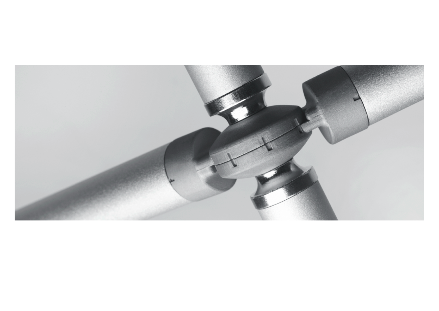
The grid settings for standard sizes
(1:1 and 1:2) of the basic surface
are marked on the joint connector.
The square surfaces and the widths
of the panels respectively can vary
between 618 x 618mm (axis 600)
and 1,220 x 1,220mm (axis 1,200).
In the format 1:2, the square sur-
faces and the widths of the panels
respectively can vary between
790 x 380mm (axis 600) up to
1,550 x 760mm (axis 1,200).
The widths of the panels depend
on the angle setting of the joint
connector. The measurement of the
edge gives the width of the panel.
The minimum height of constructiv
telvis II displays is 1.9 metres.
With a maximum base size, the dis-
plays can be up to 3.8 metres in
height.
The basic requirement for the
optimal tension of the panels and
the stability of the structure is the
arrangement of at least two panels,
which are inserted opposite each
other.
Quadratische und rechteckige
Verbauung
Neben quadratischen Grundflächen
kann constructiv telvis II in vier ver-
schiedenen rechteckigen Varianten
verbaut werden. Die Raster-
einstellungen für Standardgrößen
(1:1 und 1:2) der Grundflächen
sind am Gelenkknoten markiert.
Die quadratischen Grundflächen
bzw. Segelbreiten können zwischen
618 x 618mm (Achse 600) und
1.220 x 1.220mm (Achse 1.200)
variieren. Im Format 1:2 reichen die
rechteckigen Grundflächen bzw.
Segelbreiten von 790 x 380mm
(Achse 600) bis zu 1.550 x 760mm
(Achse 1.200).
Die Segelbreiten sind abhängig
von der Winkelstellung des Gelenk-
knotens. Aus dem antenmaß der
jeweiligen Grundfläche resultiert das
Maß der Segelbreite.
Die Mindesthöhe der Displayflächen
von constructiv telvis II beträgt 1,9
Meter. Bei maximaler Grundfläche
können die Displayhöhen bis zu 3,8
Metern betragen.
Grundvoraussetzung für die optima-
le Spannung der Segel und Stand-
festigkeit der Struktur ist die Anord-
nung mindestens zweier gegenüber-
liegend eingesetzter Segel.
Verhältnis 1:1
ratio 1:1
Verhältnis 1:2
ratio 1:2