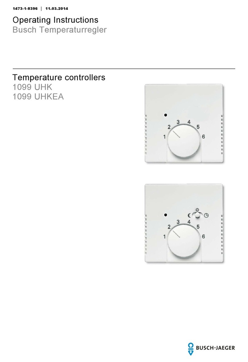
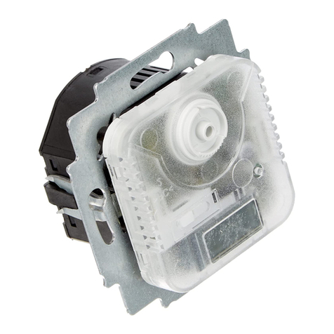
Busch-Jaeger 1094 U User manual

2CKA001473B8289
│ 05.07.2018
Product manual
Electronic room temperature controller
insert
1094
– 1097 U
1094
– 1097 UTA
1095 UF

Table of contents
Product manual 2CKA001473B8289
│2
Tableofcontents
1
Notes on the instruction manual.......................................................................................................................3
2
Safety.................................................................................................................................................................4
2.1
Information and symbols used .............................................................................................................4
2.2
Intended use..........................................................................................................................................5
2.3
Improper use .........................................................................................................................................5
2.4
Target group / Qualifications of personnel...........................................................................................6
2.4.1
Operation...........................................................................................................................................6
2.4.2
Installation, commissioning and maintenance..................................................................................6
2.5
Safety instructions.................................................................................................................................7
3
Information on protection of the environment..................................................................................................8
3.1
Environment ..........................................................................................................................................8
4
Setup and function............................................................................................................................................9
4.1
Functions...............................................................................................................................................9
4.2
Features of function and equipment.....................................................................................................9
4.3
Possible combinations ........................................................................................................................10
5
Technical data.................................................................................................................................................11
6
Connection, installation / mounting................................................................................................................12
6.1
Requirements for the electrician.........................................................................................................12
6.2
Mounting/dismantling..........................................................................................................................13
6.3
Electrical connection...........................................................................................................................15
7
Commissioning................................................................................................................................................16
8
Operation.........................................................................................................................................................17
9
Maintenance....................................................................................................................................................19
9.1
Cleaning...............................................................................................................................................19
10
Index................................................................................................................................................................20

Notes on the instruction manual
Product manual 2CKA001473B8289
│3
1 Notes on the instruction manual
Please read through this manual carefully and observe the information it contains. This will
assist you in preventing injuries and damage to property, and ensure both reliable operation and
a long service life for the device.
Please keep this manual in a safe place.
If you pass the device on, also pass on this manual along with it.
Busch-Jaeger accepts no liability for any failure to observe the instructions in this manual.
If you require additional information or have questions about the device, please contact Busch-
Jaeger or visit our Internet site at:
www.BUSCH-JAEGER.de

Safety
Product manual 2CKA001473B8289
│4
2 Safety
The device has been constructed according to the latest valid regulations governing technology
and is operationally reliable. It has been tested and left the factory in a technically safe and
reliable state.
However, residual hazards remain. Read and adhere to the safety instructions to prevent
hazards of this kind.
Busch-Jaeger accepts no liability for any failure to observe the safety instructions.
2.1 Information and symbols used
The following Instructions point to particular hazards involved in the use of the device or provide
practical instructions:
Danger
Risk of death / serious damage to health
– The respective warning symbol in connection with the signal word "Danger"
indicates an imminently threatening danger which leads to death or serious
(irreversible) injuries.
Warning
Serious damage to health
– The respective warning symbol in connection with the signal word "Warning"
indicates a threatening danger which can lead to death or serious
(irreversible) injuries.
Caution
Damage to health
– The respective warning symbol in connection with the signal word "Caution"
indicates a danger which can lead to minor (reversible) injuries.
Attention
Damage to property
– This symbol in connection with the signal word "Attention" indicates a
situation which could cause damage to the product itself or to objects in its
surroundings.
NOTE
This symbol in connection with the word "Note" indicates useful tips and
recommendations for the efficient handling of the product.
The following safety symbols are used in the operating manual:
This symbol alerts to electric voltage.

Safety
Product manual 2CKA001473B8289
│5
2.2 Intended use
The device is used in closed rooms for the regulation of the temperature for heating
systems/electric underfloor heating.
The device is intended for the following:
■Operation according to the listed technical data
■Installation in dry interior rooms
■Only suitable for installation in flush-mounted boxes according to DIN 49073-1, Part 1, or in
suitable surface-mounted housings.
■Use with the connecting options available on the device
The intended use also includes adherence to all specifications in this manual.
2.3 Improper use
Each use not listed in Chapter 2.2 “Intended use“ on page 5 is deemed improper use and can
lead to personal injury and damage to property.
Busch-Jaeger is not liable for damages caused by use deemed contrary to the intended use of
the device. The associated risk is borne exclusively by the user/operator.
The device is not intended for the following:
■Unauthorized structural changes
■Repairs
■Outdoor use
■The use in bathroom areas

Safety
Product manual 2CKA001473B8289
│6
2.4 Target group / Qualifications of personnel
2.4.1 Operation
No special qualifications are needed to operate the device.
2.4.2 Installation, commissioning and maintenance
Installation, commissioning and maintenance of the device must only be carried out by trained
and properly qualified electrical installers.
The electrical installer must have read and understood the manual and follow the instructions
provided.
The electrical installer must adhere to the valid national regulations in his/her country governing
the installation, functional test, repair and maintenance of electrical products.
The electrical installer must be familiar with and correctly apply the "five safety rules" (DIN VDE
0105, EN 50110):
1. Disconnect
2. Secure against being re-connected
3. Ensure there is no voltage
4. Connect to earth and short-circuit
5. Cover or barricade adjacent live parts

Safety
Product manual 2CKA001473B8289
│7
2.5 Safety instructions
Danger - Electric voltage!
Electric voltage! Risk of death and fire due to electric voltage of 100 … 240 V.
Dangerous currents flow through the body when coming into direct or indirect
contact with live components. This can result in electric shock, burns or even
death.
■Work on the 100 … 240 V supply system may only be performed by
authorised and qualified electricians.
■Disconnect the mains power supply before installation / disassembly.
■Never use the device with damaged connecting cables.
■Do not open covers firmly bolted to the housing of the device.
■Use the device only in a technically faultless state.
■Do not make changes to or perform repairs on the device, on its components
or its accessories.
■Keep the device away from water and wet surroundings.
Caution! - Risk of damaging the device due to external factors!
Moisture and contamination can damage the device.
■Protect the device against humidity, dirt and damage during transport,
storage and operation.

Information on protection of the environment
Product manual 2CKA001473B8289
│8
3 Information on protection of the environment
3.1 Environment
Consider the protection of the environment!
Used electric and electronic devices must not be disposed of with domestic
waste.
– The device contains valuable raw materials which can be recycled.
Therefore, dispose of the device at the appropriate collecting depot.
All packaging materials and devices bear the markings and test seals for proper disposal.
Always dispose of the packaging material and electric devices and their components via the
authorized collecting depots and disposal companies.
The products meet the legal requirements, in particular the laws governing electronic and
electrical devices and the REACH ordinance.
(EU Directive 2012/19/EU WEEE and 2011/65/EU RoHS)
(EU REACH ordinance and law for the implementation of the ordinance (EC) No.1907/2006).

Setup and function
Product manual 2CKA001473B8289
│9
4 Setup and function
4.1 Functions
The temperature controller is used to control the temperature in closed rooms.
4.2 Features of function and equipment
Article no. Features / Function
1094...
■Opens when the set temperature is reached.
■With separate connection for time-controlled reduction of night-time temperature (4
K).
■Servo valves of "closed when de-energized" design are required for the controller.
1095...
■Opens when the set temperature is reached.
■With normally open contact (not applicable for 1095...).
■With separate connection for time-controlled reduction of night-time temperature (4
K).
■With installed sliding switch and control lamp for night-time temperature reduction (4
K).
■Servo valves of "closed when de-energized" design are required for the controller.
...UF
■With normally closed contact
■With remote sensor (external temperature sensor for mounting in the floor) and
thermal feedback.
■For electric floor heating.
■Opening of the relay contact, when the set temperature is reached.
1096...
■Opens when the set temperature is reached.
■With separate connection for time-controlled reduction of night-time temperature (4
K).
■With installed sliding switch and control lamp for night-time temperature reduction (4
K).
■Servo valves of "closed when de-energized" design are required for the controller.
1097... ■With switchover contact (heating / cooling).
■Servo valves of "closed when de-energized" design are required for the controller.
...UTA
■With display of actual temperature
– Temperature display in 0.5°C steps.
– Display accuracy: ±0.5°C for load currents of ≤2 A.
– Display accuracy: ±1.5°C for load currents of >2 A.
■Automatic controller calibration.

Setup and function
Product manual 2CKA001473B8289
│10
4.3 Possible combinations
1094 U
1097 U
1094 UTA
1097 UTA
1794-...
X
1794-...
X
1095 U / 1095 UF
1096 U
1095 UTA
1096 UTA
1795-...
X
1795-...
X

Technical data
Product manual 2CKA001473B8289
│11
5 Technical data
Nominal voltage 1094...
1095...
1097...
230 V AC ±10%, 50 / 60 Hz
1096... 24 V AC ±10%, 50 Hz
Switching capacity 1094...
1095 U
1095 UTA
10 (A) A, 230 V AC
1096... 16 (2) A, 230 V AC
1096... 1 (1) A, 24 V AC
1096... 5 (2) A, 230 V AC
Connecting terminals 1094...
1095 U
1095 UTA
1096...
1097...
1.5 mm² - 2.5 mm²
1095 UF 2 x 2.5 mm² – 1 x 4 mm²
Temperature adjustment range 1094...
1095 U
1095 UTA
1096...
1097...
1 - 6 (5 - 30°C)
1095 UF 1 - 6 (10 - 50°C)
Temperature reduction 4 K
Switching temperature difference ±0.5 K
Protection type IP 20 (EN 60529)
Remote sensor 1095 UF NTC 10 kΩ / 25°C
Sensor line length 1095 UF 4 m
Ambient temperature range 0 - 30°C
Mode of operation (DIN EN
60730-1) 1B
Degree of contamination (DIN EN
60730-1) 2
Rated surge voltage (DIN EN
60730-1) 4000 V

Connection, installation / mounting
Product manual 2CKA001473B8289
│12
6 Connection, installation / mounting
Danger - Electric voltage!
Risk of death due to electrical voltage of 100 … 240 V during short-circuit in the
low-voltage conduit.
– Low-voltage and 100 … 240 V conduits must not be installed together in a
flush-mounted box!
6.1 Requirements for the electrician
Danger - Electric voltage!
Install the device only if you have the necessary electrical engineering
knowledge and experience.
■Incorrect installation endangers your life and that of the user of the electrical
system.
■Incorrect installation can cause serious damage to property, e.g. due to fire.
The minimum necessary expert knowledge and requirements for the installation
are as follows:
■Apply the "five safety rules" (DIN VDE 0105, EN 50110):
1. Disconnect
2. Secure against being re-connected
3. Ensure there is no voltage
4. Connect to earth and short-circuit
5. Cover or barricade adjacent live parts.
■Use suitable personal protective clothing.
■Use only suitable tools and measuring devices.
■Check the type of supply network (TN system, IT system, TT system) to
secure the following power supply conditions (classic connection to ground,
protective earthing, necessary additional measures, etc.).

Connection, installation / mounting
Product manual 2CKA001473B8289
│13
6.2 Mounting/dismantling
Danger - Electric voltage!
Risk of death and fire due to electric voltage of 100 to 240 V.
– Work on the 100 - 240 V supply system may only be performed by
authorised and qualified electricians.
– Disconnect the mains voltage prior to mounting and dismantling.
Caution! The device can sustain damage when coming into contact with
hard objects!
The plastic parts of the device are sensitive.
– Pull the attachment off only with your hands.
– Do not lever parts off with screwdrivers or similar hard objects.
In Germany the flush-mounted insert must only be installed in flush-mounted boxes according to
DIN 49073-1, Part 1, or suitable surface-mounted housings.
Different installation standards apply in other countries. These are to be taken into account
when used in connection with a different support ring and flush-mounted box.
The temperature controller is suitable for use in dry rooms only.
ca. 30 cm
ca. 150 cm
A B C D
Fig. 1: Installation site
Position Description
A Mounting height: approx. 150 cm
Minimum distance to doors or windows: approx. 30 cm
B Avoid mounting on cold walls (thermal bridges)
C Avoid draught and heat radiation, such as direct sunlight
D Avoid heat radiation from adjacent devices (dimmers)

Connection, installation / mounting
Product manual 2CKA001473B8289
│14
For mounting, perform the following steps:
1. Connect the device according to the circuit diagram (Page 15).
2. Fix the device in the flush-mounted box according to its design.
1
2
1
2
4
3
4
3
3. Seat the cover plate [1] on the insert.
4. Attach the adjusting knob [3]:
– Before attaching the adjusting
knob, turn the two arrows toward
each other (basic setting).
– Attach the adjusting knob
vertically, so that the position lug
[4] engages in the recess of the
drive plate [2].
Fig. 2: Attaching the adjusting knob
Notice
In connection with hot-water heating, servo valves of "closed when de-
energized" design are required for the controller.

Connection, installation / mounting
Product manual 2CKA001473B8289
│15
6.3 Electrical connection
N
N
L
L
1N
N
L
L
1
2
2
1
211
N
N
L
L
1
16A 16A 16A
230 V230 V230 V 24 V
1094...
1095...
1095 UF 1097... 1096
Fig. 3: Circuit diagrams
Icon Assignment
Connections 24 V AC
Connections 24 V AC
Input for activating the temperature reduction (see night-time reduction)
Output for controlling the heating load
Output for controlling the cooling load
**
The sensor cable must be installed in a protective cable duct.

Commissioning
Product manual 2CKA001473B8289
│16
7 Commissioning
Calibrating the display of the actual temperature value (applies only to UTA devices)
To properly control loads larger than 2 A, the heating system must be connected for calibrating
the display. After the connection, the heating system is switched on automatically for about 20
minutes. During this time, the CA icon will be displayed. After this, the display adjusts itself to
the room temperature within a few minutes.
The display shows "E3" (ERRO 3) when the mark of the adjusting knob [3] is not in the
adjustment (see fig. “Attaching the adjusting knob“ on page 14).
Before repeating the calibration procedure, the unit must be disconnected from the power
supply for at least 8 minutes.
Offset function (scale correction)
Reaching the selected room temperature depends on the ambient conditions such as heating
system capacity (at least 5 K/h min.), room size, ambient temperature, insulation, etc. That is
why the values in the scale are merely guide values. To perform a setting that is as accurate as
possible, the adjusting knob can be offset in 4 stages by a total of ±6°C as follows.
3
1
4
2
1. Pull off the adjusting knob [1].
2. Cut the position lug [2] on the bottom
side of the adjusting knob off with a
suitable tool.
3. Re-attach the adjusting knob offset to
the basic position with the desired
correcting value.
Fig. 4: Offset function
Notice
After the installation the accuracy of the switching point is established only after
an operating period of 1 to 2 hours.
For faster heating and alignment of the room temperature to the setpoint
temperature, it is recommended to set the temperature higher than required.

Operation
Product manual 2CKA001473B8289
│17
8 Operation
Fig. 5: Cover 1795-...
Mark / Icon Designation / Function
1 LED temperature reduction is active
2 Slide switch
Switch position for continuous temperature reduction
Switch position for selected temperature
Switch position for external temperature reduction
3 Adjusting knob for selecting the desired room temperature
1 = 5°C
The temperature is continuously variable
with the adjusting knob [3]. The
difference in temperature between two
digits is approximately 5°C. For
temperature adjustment and values, see
opposite
2 = 10°C
3 = 15°C
4 = 20°C
5 = 25°C
6 = 30°C
1
23 4 5
6
1
23 4 5
6
1
1
2
2
3
3

Operation
Product manual 2CKA001473B8289
│18
Fig. 6: Cover with excerpt 1795 TA-...
Mark / Icon Designation / Function
4 Icon in the display
Heating switched on
Temperature reduction active
Calibration
1
23 4 5
61
23 4 5
6
4
4
CACA

Maintenance
Product manual 2CKA001473B8289
│19
9 Maintenance
9.1 Cleaning
Caution! - Risk of damaging the device!
■When spraying on cleaning agents, these can enter the device through
crevices.
– Do not spray cleaning agents directly onto the device.
■Aggressive cleaning agents can damage the surface of the device.
– Never use caustic agents, abrasive agents or solvents.
Clean dirty devices with a soft dry cloth.
– If this is insufficient, the cloth can be moistened slightly with a soap solution.

Index
Product manual 2CKA001473B8289
│20
10 Index
C
Cleaning.................................................................................19
Commissioning......................................................................16
Connection, installation /mounting.......................................12
D
dismantling.............................................................................13
E
Electrical connection..............................................................15
Environment.............................................................................8
F
Features ofequipment.............................................................9
Features offunctions...............................................................9
Functions..................................................................................9
I
Improper use............................................................................5
Information and symbols used................................................4
Information on protection of the environment.........................8
Intended use............................................................................5
M
Maintenance..........................................................................19
Mounting.................................................................................13
N
Notes on the instruction manual..............................................3
O
Operation............................................................................6,17
P
Possible combinations...........................................................10
Q
Qualification of personnel........................................................6
R
Requirements for the electrician...........................................12
S
Safety........................................................................................4
Safety instructions....................................................................7
Setup and function...................................................................9
T
Targetgroup.............................................................................6
Technical data........................................................................11
This manual suits for next models
8
Table of contents
Other Busch-Jaeger Temperature Controllers manuals