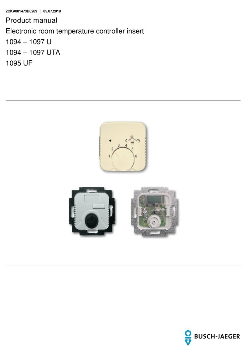
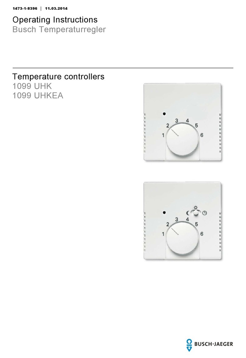
Busch-Jaeger 1094 User manual

1
473-1-8289 │24.03.2014
O
perating Instructions
T
emperaturregler
Pos:2 /#Neustruktur#/Online-Dokumentation(+KNX)/Titelblätter/Temperaturregler/Titelblatt1094....1097 @ 38\mod_13945 43892488_15.docx @ 302224 @ @ 1
Temperature controller
1094….1097 U
1094….1097 UTA
1095 UF
=== Ende der Liste für Textmarke Cover ===

Operating Instructions
Temperaturregler
Operating Instructions | 1473-1-8289 — 2 —
Pos: 4 /#Neustruktur#/ Online-Dokument ation (+KNX)/Inhal tsverzeichnis (- -> Für alle Dokumente <-- )/Inhaltsverzeichni s @ 19\mod_1320649044386_ 15.docx @ 109653 @ @ 1
1Safety....................................................................................................................................................................... 3
2Intended use ............................................................................................................................................................ 3
3Environment............................................................................................................................................................. 3
4Operation ................................................................................................................................................................. 4
5Technical data.......................................................................................................................................................... 5
6Setup and function................................................................................................................................................... 6
6.1Features of function and equipment........................................................................................................ 6
6.2Possible combinations ............................................................................................................................ 7
7Installation and electrical connection ....................................................................................................................... 8
7.1Requirements for the electrician ............................................................................................................. 8
7.2Mounting ................................................................................................................................................. 8
7.3Electrical connection ............................................................................................................................. 10
8Commissioning ...................................................................................................................................................... 11
8.1Calibrating the display of the actual temperature value (applies only to UTA devices) ......................... 11
8.2Offset function(scale correction)......................................................................................................... 11
=== Ende der Liste für Textmarke TOC ===

Operating Instructions
Temperaturregler Safety
Operating Instructions | 1473-1-8289 — 3 —
Pos:6 /#Neustruktur#/Online-Dokumentation (+KNX)/Überschriften(--> Füralle Dokumente<--)/1.Ebene/S - T/Si cherheit @ 18\mod_13026127 91790_15.docx @ 103357 @ 1 @ 1
1 Safety
Pos:7 /#Neustruktur#/Online-Dokumentation (+KNX)/Sicherheitshinweiseund Hinweise(--> Für alleDokumente<--)/Warnhinweise/Sicherheit - 230 V @ 18\mod_130260681675 0_15.docx @ 103308 @ @ 1
Warnin
g
Electric voltage!
Risk of death and fire due to electrical voltage of 230 V.
– Work on the 230V supply system may only be performed by authorised electricians!
– Disconnect the mains power supply prior to installation and/or disassembly!
Pos:8 /#Neustruktur#/Online-Dokumentation (+KNX)/Überschriften(--> Füralle Dokumente<--)/1.Ebene/A - F/Bestimmungsgemäßer Gebr auch @ 18\mod_1302763321316 _15.docx @ 103483 @ 1 @ 1
2 Intended use
Pos: 9 /#Neustruktur#/ Online-Dokument ation (+KNX)/Besti mmungsgemäßer Gebrauc h (--> Für alle Dokumente <- -)/Busch-Dimmer/B estimmungsgemäßer Gebr auch @ 23\mod_13353504498 57_15.docx @ 208763 @ @ 1
The device is to be used exclusively with the components that are supplied and licensed as described in chapter
"Setup and function".
Pos:10 /#Neustruktur#/Online-Dokumentation(+KNX)/Überschriften (--> Füralle Dokumente <--)/1. Ebene/U - Z/Umwelt @ 18\mod_130261415 8967_15.docx @ 103383 @ 1 @ 1
3 Environment
Pos: 11 /#Neustruktur #/Online-Dokumen tation (+KNX)/Sic herheitshinweise und Hinweise (--> Füralle Dokumente<--)/Hinweise- Umwelt/Hinweis - Umwelt- HinweisElektrogeräte @ 18\mod_1302763973 434_15.docx @ 103500 @ @ 1
Consider the protection of the environment!
Used electric and electronic devices must not be disposed of with domestic waste.
– The device contains valuable raw materials which can be recycled. Therefore, dispose of the
device at the appropriate collecting depot.
Pos: 12 /#Neustruktur #/Online-Dokumen tation (+KNX)/Sic herheitshinweise und Hinweise (--> Für alleDokumente<--)/Hinweise - Umwelt/Hinweis- Umwelt - Entsorgung Elektrogeräte @ 20\mod_1325760695972_15.docx @ 136583 @ @ 1
All packaging materials and devices bear the markings and test seals for proper disposal. Always dispose of the
packaging material and electric devices and their components via the authorized collecting depots and disposal
companies.
The products meet the legal requirements, in particular the laws governing electronic and electrical devices and
the REACH ordinance.
(EU Directive 2002/96/EC WEEE and 2002/95/EC RoHS)
(EU REACH ordinance and law for the implementation of the ordinance (EC) No.1907/2006)
Pos:13 /#Neustruktur#/Online-Dokumentation(+KNX)/Steuermodule - Online-Dokumentation (--> Füralle Dokumente<--)/++++++++++++Sei tenumbruch ++++++++ ++++ @ 9\mod_1268898668093_0. docx @ 52149 @ @ 1

Operating Instructions
Temperaturregler Operation
Operating Instructions | 1473-1-8289 — 4 —
Pos:14 /#Neustruktur#/Online-Dokumentation(+KNX)/Überschriften (--> Füralle Dokumente <--)/1. Ebene/A - F/Bedienung @ 11\mod_1279185 541649_15.doc x@ 83043 @ 1 @ 1
4 Operation
Pos: 15 /#Neustruktur #/Online-Dokumen tation (+KNX)/Bedienu ng/Temperaturreg ler/Bedienung Zentr alscheibe für 1094....1097 @ 26\mod _1342699745536_15.doc x@ 224317 @ @ 1
Fig. 1: Cover
Mark / Symbol Designation / Function
A LED - temperature reduction active
B Slide switch
C Control knob for selecting the desired room temperature
1 = 5°C
The temperature is continuously variable with the adjusting knob (C). The difference in
temperature between two digits is approximately 5°C. For temperature adjustment and values,
see the opposite columns.
2 = 10°C
3 = 15°C
4 = 20°C
5 = 25°C
6 = 30°C
Switch position for external temperature reduction
Switch position for selected temperature
Switch position for continuous temperature reduction
Fig. 2: Cover with cutout for display of actual temperature value (only for ... UTA)
Symbol in the display Designation / Function
Heating switched on
Temperature reduction active
Calibration Calibration
Pos:16 /#Neustruktur#/Online-Dokumentation(+KNX)/Steuermodule - Online-Dokumentation (--> Füralle Dokumente<--)/++++++++++++Sei tenumbruch ++++++++ ++++ @ 9\mod_1268898668093_0. docx @ 52149 @ @ 1
1
2
34
5
6
A
B
C
1
2
34
5
6
A
B
C

Operating Instructions
Temperaturregler Technical data
Operating Instructions | 1473-1-8289 — 5 —
Pos:17 /#Neustruktur#/Online-Dokumentation(+KNX)/Überschriften (--> Füralle Dokumente <--)/1. Ebene/S - T/Technische Daten @ 11\ mod_1279185386320_15. docx @ 83019 @ 1 @ 1
5 Technical data
Pos:18 /#Neustruktur#/Online-Dokumentation(+KNX)/TechnischeDaten/Temperaturregler/TechnischeDaten1094....1097 @ 38\mod_1384431 661394_15.docx @ 300514 @ @ 1
General
Nominal voltage 230 V AC ± 10%, 50/60 Hz
24 V AC ± 10%, 50 Hz
1094, 1095, 1095 UF, 1097 U / UTA
1096 U / UTA
Switching capacity 10 (4) A, 230 V AC
16 A, 230 V AC
1 (1) A, 24 V AC
5 (2) A, 230 V AC
1094, 1095 U / UTA
1095 UF
1096 U / UTA
1097 U / UTA
Connection 1.5 mm² … 2.5 mm²
2 x 2.5 mm² – 1 x 4 mm²
1094, 1095, 1095 UF, 1096 U / UTA, 1097 U / UTA
1095 UF
Temperature adjustment range 1 … 6 (5 … 30°C)
1 … 6 (10 … 50°C)
1094, 1095, 1095 UF, 1096 U / UTA, 1097 U / UTA
1095 UF
Temperature reduction 4 K
Switching temperature difference ±0.5 K
Protection type IP 20, EN (60529)
Temperature sensor 1095 UF NTC 10 kΩ/ 25°C
Maximum cable length 1095 UF 4 m
Operating temperature range 0 ...30 °C
Mode of operation (DIN EN 60730-1) 1B
Degree of contamination (DIN EN 60730-1) 2
Rated surge voltage (DIN EN 60730-1) 4000 V
Pos:19 /#Neustruktur#/Online-Dokumentation(+KNX)/Steuermodule - Online-Dokumentation (--> Füralle Dokumente<--)/++++++++++++Sei tenumbruch ++++++++ ++++ @ 9\mod_1268898668093_0. docx @ 52149 @ @ 1

Operating Instructions
Temperaturregler Setup and function
Operating Instructions | 1473-1-8289 — 6 —
Pos:20 /#Neustruktur#/Online-Dokumentation(+KNX)/Überschriften (--> Füralle Dokumente <--)/1. Ebene/A - F/Aufbau und Funktion @ 11\mod _1279185435352_15.doc x @ 83027 @ 1 @ 1
6 Setup and function
Pos: 21 /#Neustruktur #/Online-Dokumen tation (+KNX)/Aufbau un d Funktion/Temperatur regler/Verwendun g 1094....1097, 1098 @ 26\mod_13427663 79475_15.docx @ 224403 @ @ 1
The temperature controller is used to control the temperature in closed rooms.
Pos:22 /#Neustruktur#/Online-Dokumentation(+KNX)/Überschriften (--> Füralle Dokumente <--)/2. Ebene/A - F/Funktions- und Auss tattungsmerkmale @ 23\ mod_1336557630140_15. docx @ 209136 @ 2 @ 1
6.1 Features of function and equipment
Pos: 23 /#Neustruktur #/Online-Dokumen tation (+KNX)/Aufbau un d Funktion/Temperatur regler/Funktione n 1094....1097 @ 26\mod_1342708498968_1 5.docx @ 224389 @ @ 1
Article no. Features / Function
1094 … • Opens when the set temperature is reached.
• With separate connection for time-controlled reduction of nighttime temperature (4K).
• Servo valves of "closed when de-energized“ design are required for the controller.
1095 … • Opens when the set temperature is reached.
• With normally open contact (not applicable for 1095 UF)
• With separate connection for time-controlled reduction of nighttime temperature (4K).
• With installed sliding switch and control lamp for nighttime temperature reduction (4 K).
• Servo valves of "closed when de-energized“ design are required for the controller.
… UF • With normally closed contact
• With remote sensor (external temperature sensor for mounting in the floor) and thermal feedback.
• For electric underfloor heating
• Opening of the relay contact, when the set temperature is reached.
1096 … • Opens when the set temperature is reached.
• With separate connection for time-controlled reduction of nighttime temperature (4K).
• With installed sliding switch and control lamp for nighttime temperature reduction (4 K).
• Servo valves of "closed when de-energized“ design are required for the controller.
1097 … • With switchover contact (heating / cooling)
• Servo valves of "closed when de-energized“ design are required for the controller.
… UTA • With display of actual temperature
- Temperature display in steps of 0.5°C
• Display accuracy: ±0,5°C for load currents of ≤2 A
– Display accuracy: ±1,5°C for load currents of >2 A
• Automatic controller calibration
Pos:24 /#Neustruktur#/Online-Dokumentation(+KNX)/Steuermodule - Online-Dokumentation (--> Füralle Dokumente<--)/++++++++++++Sei tenumbruch ++++++++ ++++ @ 9\mod_1268898668093_0. docx @ 52149 @ @ 1

Operating Instructions
Temperaturregler Setup and function
Operating Instructions | 1473-1-8289 — 7 —
Pos:25 /#Neustruktur#/Online-Dokumentation(+KNX)/Überschriften (--> Füralle Dokumente <--)/2. Ebene/G - L/Kombinationsmögli chkeiten @ 19\mod_1320312 769153_15.doc x@ 10952 0 @ 2 @ 1
6.2 Possible combinations
Pos: 26 /#Neustruktur #/Online-Dokumen tation (+KNX)/Kombina tionsmöglichkei ten/Temperaturreg ler/Kombinations möglichkeiten 1094.. ..1097 @ 26\mod_134276649 9439_15.docx @ 224417 @ @ 1
1094 U
1097 U
1094 UTA
1097 UTA
1794-…
X
1794-…
X
1095 U / UF
1096 U
1095 UTA
1096 UTA
1795-…
X
1795-…
X
Pos:27 /#Neustruktur#/Online-Dokumentation(+KNX)/Steuermodule - Online-Dokumentation (--> Füralle Dokumente<--)/++++++++++++Sei tenumbruch ++++++++ ++++ @ 9\mod_1268898668093_0. docx @ 52149 @ @ 1

Operating Instructions
Temperaturregler Installation and electrical
connection
Operating Instructions | 1473-1-8289 — 8 —
Pos:28 /#Neustruktur#/Online-Dokumentation(+KNX)/Überschriften (--> Füralle Dokumente <--)/1. Ebene/M - O/Montage und elektri scher Anschluss @ 23\mod_1336 477157864_15.doc x@ 209 033 @ 1 @ 1
7 Installation and electrical connection
Pos: 29 /#Neustruktur #/Online-Dokumen tation (+KNX)/Sic herheitshinweise und Hinweise (--> Für alleDokumente<--)/Warnhinweise/Sicherheit- Niederspannu ngs- und 230 V-Leitungen @ 23\ mod_1336558868201_15. docx @ 209164 @ @ 1
Warnin
g
Electric voltage!
Risk of death due to electrical voltage of 230 V during short-circuit in the low-voltage line.
– Low-voltage and 230 V lines must not be installed together in a flush-mounted socket!
Pos: 30 /#Neustruktur #/Online-Dokumen tation (+KNX)/Sic herheitshinweise und Hinweise (--> Für alleDokumente<--)/Warnhinweise/Sicherheit- Fachkenntnisse @ 23\mod_1336 559183027_15.doc x@ 209 179 @ 2 @ 1
7.1 Requirements for the electrician
Warnin
g
Electric voltage!
Install the device only if you have the necessary electrical engineering knowledge and experience.
• Incorrect installation endangers your life and that of the user of the electrical system.
• Incorrect installation can cause serious damage to property, e.g. due to fire.
The minimum necessary expert knowledge and requirements for the installation are as follows:
• Apply the "five safety rules" (DIN VDE 0105, EN 50110):
1. Disconnect from power;
2. Secure against being re-connected;
3. Ensure there is no voltage;
4. Connect to earth and short-circuit;
5. Cover or barricade adjacent live parts.
• Use suitable personal protective clothing.
• Use only suitable tools and measuring devices.
• Check the supply network type (TN system, IT system, TT system) to secure the following
power supply conditions (classic connection to ground, protective earthing, necessary
additional measures, etc.).
Pos:31 /#Neustruktur#/Online-Dokumentation(+KNX)/Überschriften (--> Füralle Dokumente <--)/2. Ebene/M - O/Montage @ 18\mod_13026159 60458_15.docx @ 103424 @ 2 @ 1
7.2 Mounting
Pos: 32 /#Neustruktur #/Online-Dokumen tation (+KNX)/Sic herheitshinweise und Hinweise (--> Für alleDokumente<--)/Warnhinweise/Sicherheit- 230 V @ 18\ mod_1302606816750_15.d ocx @ 103308 @ @ 1
Warnin
g
Electric voltage!
Risk of death and fire due to electrical voltage of 230 V.
– Work on the 230V supply system may only be performed by authorised electricians!
– Disconnect the mains power supply prior to installation and/or disassembly!
Pos:33 /#Neustruktur#/Online-Dokumentation(+KNX)/Steuermodule - Online-Dokumentation (--> Füralle Dokumente<--)/++++++++++++Sei tenumbruch ++++++++ ++++ @ 9\mod_1268898668093_0. docx @ 52149 @ @ 1

Operating Instructions
Temperaturregler Installation and electrical
connection
Operating Instructions | 1473-1-8289 — 9 —
Pos: 34 /#Neustruktur #/Online-Dokumen tation (+KNX)/Montage/ alle Geräte/Montag e - UP-Dosen - DIN 49073-1 oder geei gnetes Aufputzg ehaeuse - Ohne Docvariable @ 25\ mod_1340354979636_15. docx @ 219890 @ @ 1
The flush-mounted insert must only be installed in flush-mounted wall boxes according to DIN 49073-1, Part 1, or
suitable surface-mounted housings.
Pos: 35 /#Neustruktur #/Online-Dokumen tation (+KNX)/Montage/ Temperaturregler /Montage 1094....1097 @ 26\mod_1342 768559622_15.doc x@ 2244 32 @ @ 1
The temperature controller is suitable for use in dry rooms only.
Fig. 3: Installation site
Position Description
A Mounting height: approx. 150 cm
Minimum distance to doors or windows: approx. 30 cm
B Avoid mounting on cold walls (thermal bridges)
C Avoid draught and heat radiation, such as direct sunlight
D Avoid heat radiation from adjacent devices (dimmers)
1. Connect the device according to the circuit diagram.
Note
In connection with hot-water heating, servo valves of "closed when de-energized“ design are
required for the controller.
2. Fix the device in the flush-mounted box according to its design.
Fig. 4: Attaching the adjusting knob
1 Cover plate (cover) | 2 Drive plate | 3 Adjusting knob (rear side) | 4 Position lug
3. Seat the cover plate (1) on the insert.
4. Attach the adjusting knob (3):
- To attach the adjusting knob, turn the two arrows towards each other (basic position).
- Attach the adjusting knob vertically, so that the position lug (1) engages in the recess of the drive plate
(2).
Pos:36 /#Neustruktur#/Online-Dokumentation(+KNX)/Steuermodule - Online-Dokumentation (--> Füralle Dokumente<--)/++++++++++++Sei tenumbruch ++++++++ ++++ @ 9\mod_1268898668093_0. docx @ 52149 @ @ 1
ca. 30 cm
ca. 150 cm
ABCD
4
13
2

Operating Instructions
Temperaturregler Installation and electrical
connection
Operating Instructions | 1473-1-8289 — 10 —
Pos:37 /#Neustruktur#/Online-Dokumentation(+KNX)/Überschriften (--> Füralle Dokumente <--)/2. Ebene/A - F/Elektrischer Ansc hluss @ 21\mod_13281770517 24_15.docx @ 138042 @ 2 @ 1
7.3 Electrical connection
Pos:38 /#Neustruktur#/Online-Dokumentation(+KNX)/Anschluss/Temperaturregler/Anschluss 1094....1097@ 38\ mod_1395414417382_1 5.docx @ 302374 @ @ 1
1094 … / 1095 … 1095 UF 1097 … 1096 …
Fig. 5: Circuit diagrams
Icon Assignment
Connections 24 V AC
Connections 24 V AC
Input for activating the temperature reduction (see nighttime reduction)
Output for controlling the heating load
Output for controlling the cooling load
* The sensor cable must be routed in a protective tube.
Pos:39 /#Neustruktur#/Online-Dokumentation(+KNX)/Steuermodule - Online-Dokumentation (--> Füralle Dokumente<--)/++++++++++++Sei tenumbruch ++++++++ ++++ @ 9\mod_1268898668093_0. docx @ 52149 @ @ 1
N
N
L
L
1N
N
L
L
12
2
1
211
N
N
L
L
1
16A 16A 16A
230 V230 V230 V 24 V

Operating Instructions
Temperaturregler Commissioning
Operating Instructions | 1473-1-8289 — 11 —
Pos:40 /#Neustruktur#/Online-Dokumentation(+KNX)/Überschriften (--> Füralle Dokumente <--)/1. Ebene/G - L/Inbetriebnahme @ 11\ mod_1279185496977_15. docx @ 83035 @ 1 @ 1
8 Commissioning
Pos: 41 /#Neustruktur #/Online-Dokumen tation (+KNX)/Inbetri ebnahme/Temperatur regler/Inbetri ebnahme 1094....1097 @ 26\mod_134278 4726684_15.doc x@ 224476 @ 22 @ 1
Notes on commissioning
After the installation the accuracy of the switching point is established only after an operating
period of 1 to 2 hours.
For faster heating and alignment of the room temperature to the setpoint temperature, it is
recommended to initially set the temperature higher than required.
8.1 Calibrating the display of the actual temperature value (applies only to UTA devices)
To properly control loads larger than 2 A, the heating system must be connected for calibrating the display. After
the connection, the heating system is switched on automatically for about 20 minutes. During this time, the “CA”
symbol will be displayed. After this, the display adjusts itself to the room temperature within a few minutes.
Before repeating the calibration procedure, the unit must be disconnected from the power supply for at least 8
minutes.
8.2 Offset function(scale correction)
Reaching the selected room temperature depends on the ambient conditions such as heating system capacity (at
least 5°K/h min.), room size, ambient temperature, insulation, etc. That is why the values in the scale are merely
guide values. To obtain a setting that is as accurate as possible, the adjusting knob can be offset in 4 stages by a
total of ±6°C as follows. Compare illustration 4:
1. Pull off the adjusting knob (3).
2. Cut the position lug (1) on the bottom side of the adjusting knob off with a suitable tool.
3. Re-attach the adjusting knob, which has been offset to the basic position with the desired correcting value.
=== Ende der Liste für Textmarke Content ===

Operating Instructions
Temperaturregler
1473-1-8289 | 24.03.2014
Pos:43 /#Neustruktur#/Online-Dokumentation(+KNX)/Rückseiten(--> Füralle Dokumente<--)/Rückseite - BJE-Variante@ 32\mod_1357201421897_15.doc x@ 2621 32 @ @ 1
A
member of the ABB Group
Busch-Jaeger Elektro GmbH
PO box
58505 Lüdenscheid
Freisenbergstraße 2
58513 Lüdenscheid
Germany
www.BUSCH-JAEGER.de
[email protected]bb.com
Central sales service:
Phone: +49 (0) 2351 956-1600
Fax: +49 (0) 2351 956-1700
Notice
We reserve the right to at all times make
technical changes as well as changes to the
contents of this document without prior notice.
The detailed specifications agreed to at the time
of ordering apply to all orders. ABB accepts no
responsibility for possible errors or
incompleteness in this document.
We reserve all rights to this document and the
topics and illustrations contained therein. The
document and its contents, or extracts thereof,
must not be reproduced, transmitted or reused by
third parties without prior written consent by ABB.
Copyright© 2014 Busch-Jaeger Elektro GmbH
A
ll rights reserved
=== Ende der Liste für Textmarke Backcover = ==
Other manuals for 1094
1
This manual suits for next models
6
Table of contents
Other Busch-Jaeger Temperature Controllers manuals
Popular Temperature Controllers manuals by other brands

Danfoss
Danfoss ECL Comfort 110 User guide, installation & maintenance

Logia
Logia LOWSA100SW user guide

LaserLiner
LaserLiner ThermoSensor Clamp operating instructions

AFRISO
AFRISO CosiTherm FT operating instructions

BASETech
BASETech MH-555C operating instructions

RKC INSTRUMENT
RKC INSTRUMENT REX-F9000 instruction manual