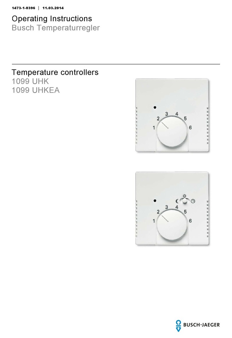
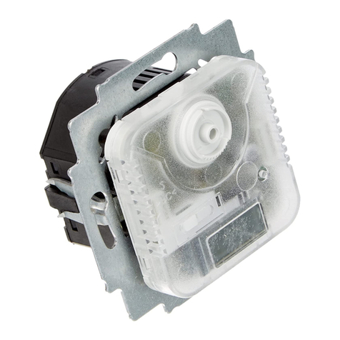
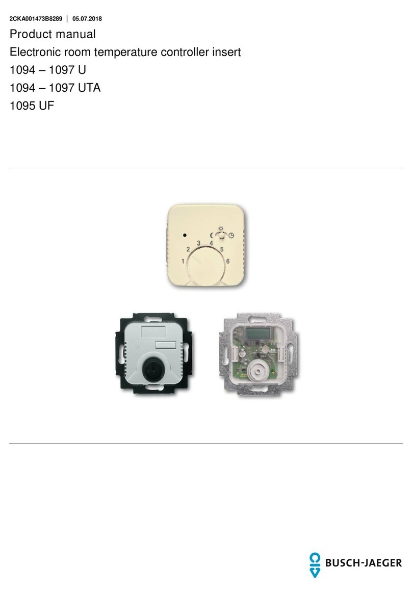
Busch-Jaeger 1094 User manual

1473
-1-8289 │ Rev. 01 │ 17.12.2012
Operating Instructions
Temperaturregler
Pos: 2 /#N eus tru k tur #/O nl in e-D o ku men ta ti o n ( + KN X) /T it el bl ät ter /T e m per at ur r egl er /Ti t elbl att 10 94 ... . 109 7 @ 26\mod_1342698041601_15.docx@224303@ @ 1
Temperature controller
1094….1097 U
1094….1097 UTA
1095 UF
1795
…
=== En de d er Li st e für T e xt m ar ke Co ver = ==

Operating Instructions
Temperaturregler
Operating Instructions | 1473-1-8289
— 2 —
Pos: 4 /#N eus tru k tur #/O nl in e-D ok um en ta tio n ( +KN X)/I n halt s verz ei c hnis (--> Für alle D o kume nte < --)/I nh alts v erz ei ch nis @ 19 \mod_1320649044386_15.docx@ 109653@ @ 1
1Safety....................................................................................................................................................................... 3
2Intended use ............................................................................................................................................................ 3
3Environment............................................................................................................................................................. 3
4Operation ................................................................................................................................................................. 4
5Technical data.......................................................................................................................................................... 5
6Setup and function................................................................................................................................................... 6
6.1 Features of function and equipment........................................................................................................ 6
6.2 Possible combinations ............................................................................................................................ 7
7Installation and electrical connection ....................................................................................................................... 8
7.1 Requirements for the electrician ............................................................................................................. 8
7.2 Mounting ................................................................................................................................................. 8
7.3 Electrical connection ............................................................................................................................. 10
8Commissioning ...................................................................................................................................................... 11
8.1 Calibrating the display of the actual temperature value (applies only to UTA devices) ......................... 11
8.2 Offset function(scale correction)......................................................................................................... 11
=== En de d er Li st e für T e xt m ar ke TOC ===

Operating Instructions
Temperaturregler
Safety
Operating Instructions | 1473-1-8289
— 3 —
Pos: 6 /#N eus tru k tur #/O nl in e-Dokumentation(+KNX)/ Ü bersc hr ift e n (--> Für alle D o ku m ent e < --)/1. Ebene/S- T/Si ch er hei t @ 18 \mod_1302612791790_15.docx@ 103357@ 1 @ 1
1 Safety
Pos: 7 /#N eus tru k tur #/O nl in e-D ok um en ta tio n ( +KN X)/ Sic her h eits hi n weis e un d Hi n weis e ( --> F ür all e D o kum ent e < --)/W ar nhi n wei s e/ Si ch erh ei t - 230V @ 18\mod_1302606816750_15.docx@ 103308@ @ 1
Warning
Electric voltage!
Risk of death and fire due to electrical voltage of 230 V.
– Work on the 230V supply system may only be performed by authorised electricians!
– Disconnect the mains power supply prior to installation and/or disassembly!
Pos: 8 /#N eus tru k tur #/O nl in e-D ok um enta ti on ( +KN X) /Ü bers c hrif te n ( --> Für al le D o ku m ent e < --)/1. Ebene/A- F/Bes ti mm u ngs ge mäß er Gebra uc h @ 18\mod_1302763321316_15.docx@ 103483@ 1 @ 1
2 Intended use
Pos: 9 /#N eus tru k tur #/O nl in e-Dokumentation(+KNX)/BestimmungsgemäßerGebrauch(-->Für alleDokumente<--)/Bus ch-D i mmer /B esti m mung sg em äß er G ebr a uch @ 2 3\mod_1335350449857_15.docx@ 208763@ @ 1
The device is to be used exclusively with the components that are supplied and licensed as described in chapter
"Setup and function".
Pos: 10 / #N e ustr ukt ur# /O nl ine-Do ku me nt ati on ( +K N X) /Üb er sc hr i ft en (--> F ür al l e D o kume nt e <--) /1. Eb ene/U - Z /U mw elt @ 18 \mod_1302614158967_15.docx@ 103383@ 1 @ 1
3 Environment
Pos: 11 / #N e ustr ukt ur# /O nl in e-Dokumentation(+KNX)/SicherheitshinweiseundHinweise(-->Für alleDokumente<--)/Hinweise- Umwelt/Hinweis - Umwelt - HinweisElektrogeräte@ 18\mod_1302763973434_15.docx@103500@ @ 1
Consider the protection of the environment!
Used electric and electronic devices must not be disposed of with domestic waste.
– The device contains valuable raw materials which can be recycled. Therefore, dispose of the
device at the appropriate collecting depot.
Pos: 12 / #N e ustr ukt ur# /O nl in e-Dokumentation(+KNX)/SicherheitshinweiseundHinweise(-->Für alleDokumente<--)/Hinweise- Umwelt/Hinweis - Umwelt - Entsorgung Elektrogeräte@ 20\mod_1325760695972_15.docx@ 136583@ @ 1
All packaging materials and devices bear the markings and test seals for proper disposal. Always dispose of the
packaging material and electric devices and their components via the authorized collecting depots and disposal
companies.
The products meet the legal requirements, in particular the laws governing electronic and electrical devices and
the REACH ordinance.
(EU Directive 2002/96/EC WEEE and 2002/95/EC RoHS)
(EU REACH ordinance and law for the implementation of the ordinance (EC) No.1907/2006)
Pos: 13 / #N e ustr ukt ur# /O nl in e-D oku me ntati on ( +KN X) /S teuer mod ul e - Online-Dokumentation(-->Für alleDokumente<--)/++++++++++++Seitenumbruch++++++++++++@ 9\mod_1268898668093_0.docx@ 52149@ @ 1

Operating Instructions
Temperaturregler
Operation
Operating Instructions | 1473-1-8289
— 4 —
Pos: 14 / #N e ustr ukt ur# /O nl in e-D ok u ment ati on (+ KN X) /Ü ber sc hrif t en (--> F ür al l e D ok ume nte <--)/1. Ebene/A- F/ B edi e nu ng @ 1 1\mod_1279185541649_15.docx@ 83043@ 1 @ 1
4 Operation
Pos: 15 / #N e ustr ukt ur# /O nl in e-D oku me ntati on ( +KN X) /B edi enu ng /T emp erat urr egl er /B edi enu ng Ze ntr als c hei be f ür 1 094 ... .1 097 @ 26 \mod_1342699745536_15.docx@224317@ @ 1
Fig. 1: Cover
Mark / Symbol
Designation / Function
A
LED - temperature reduction active
B
Slide switch
C
Control knob for selecting the desired room temperature
1
= 5°C
The temperature is continuously variable with the adjusting knob (C). The difference in
temperature between two digits is approximately 5°C. For temperature adjustment and values,
see the opposite columns.
2
= 10°C
3
= 15°C
4
= 20°C
5
= 25°C
6
= 30°C
Switch position for external temperature reduction
Switch position for selected temperature
Switch position for continuous temperature reduction
Fig. 2: Cover with cutout for display of actual temperature value (only for ... UTA)
Symbol in the display
Designation / Function
Heating switched on
Temperature reduction active
Calibration
Calibration
Pos: 16 / #N e ustr ukt ur# /O nl in e-D oku me ntati on ( +KN X) /S teuer mod ul e - Online-Dokumentation(-->Für alleDokumente<--)/++++++++++++Seitenumbruch++++++++++++@ 9\mod_1268898668093_0.docx@ 52149@ @ 1

Operating Instructions
Temperaturregler
Technical data
Operating Instructions | 1473-1-8289
— 5 —
Pos: 17 / #N e ustr ukt ur# /O nl in e-Dokumentation(+KNX)/Übersc hr ift en ( --> Für al l e D ok ume nt e <--)/1.Ebene/S- T/TechnischeDaten @ 11\mod_1279185386320_15.docx@ 83019@ 1 @ 1
5 Technical data
Pos: 18 / #N e ustr ukt ur# /O nl in e-Dokumentation(+KNX)/TechnischeDaten/Temperaturregler/TechnischeDaten 1094....1097@26\mod_1342705889950_15.docx@ 224374@ @ 1
General
Nominal voltage 230 V AC ± 10%, 50/60 Hz
24 V AC ± 10%, 50 Hz
1094, 1095, 1095 UF, 1097
1096
Switching capacity 10 (4) A, 230 V AC
16 A, 230 V AC
1 (1) A, 24 V AC
5 (2) A, 230 V AC
1094, 1095
1095 U
1096
1097
Connection 1.5 mm² … 2.5 mm²
2 x 2.5 mm² – 1 x 4 mm²
1094, 1095, 1095, 1097
1095 UF
Temperature adjustment range 1 … 6 (5 … 30°C)
1 … 6 (10 … 50°C)
1094, 1095, 1095, 1097
1095 UF
Temperature reduction 4 K
Switching temperature difference
±0.5 K
Protection type
IP 20, EN (60529)
Temperature sensor 1095 UF
NTC 10 kΩ / 25°C
Maximum cable length 1095 UF
4 m
Operating temperature range
0 ...30 °C
Pos: 19 / #N e ustr ukt ur# /O nl in e-D oku me ntati on ( +KN X) /S teuer mod ul e - Online-Dokumentation(-->Für alleDokumente<--)/++++++++++++Seitenumbruch++++++++++++@ 9\mod_1268898668093_0.docx@ 52149@ @ 1

Operating Instructions
Temperaturregler
Setup and function
Operating Instructions | 1473-1-8289
— 6 —
Pos: 20 / #N e ustr ukt ur# /O nl in e-D ok u ment ati on (+ KN X) /Ü ber sc hrif t en (--> F ür al l e D ok ume nte <--)/1. Ebene/A- F/ Aufba u und Funktion@11\mod_1279185435352_15.docx@ 83027@ 1 @ 1
6 Setup and function
Pos: 21 / #N e ustr ukt ur# /O nl in e-Dokumentation(+KNX)/AufbauundFunktion/Temperaturregler/Verwendung1094....1097,1098@ 26\mod_1342766379475_15.docx@ 22 440 3 @ @ 1
The temperature controller is used to control the temperature in closed rooms.
Pos: 22 / #N e ustr ukt ur# /O nl in e-D ok u ment ati on (+ KN X) /Ü ber sc hrif t en (--> F ür al l e D ok ume nte <--)/2. Ebene/A- F/Funktions-u nd Aus st att ung s mer kmal e @ 23 \mod_1336557630140_15.docx@ 209136@ 2 @ 1
6.1 Features of function and equipment
Pos: 23 / #N e ustr ukt ur# /O nl in e-Dokumentation(+KNX)/AufbauundFunktion/Temperaturregler/Funktionen1094....1097@ 26\mod_1342708498968_15.docx@ 224389@ @ 1
Article no.
Features / Function
1094 … •Opens when the set temperature is reached.
•With separate connection for time-controlled reduction of nighttime temperature (4K).
•Servo valves of "closed when de-energized“ design are required for the controller.
1095 … •Opens when the set temperature is reached.
•With normally open contact (not applicable for 1095 UF)
•With separate connection for time-controlled reduction of nighttime temperature (4K).
•With installed sliding switch and control lamp for nighttime temperature reduction (4 K).
•Servo valves of "closed when de-energized“ design are required for the controller.
… UF •With normally closed contact
•With remote sensor (external temperature sensor for mounting in the floor) and thermal feedback.
•For electric underfloor heating
•Opening of the relay contact, when the set temperature is reached.
1096 … •Opens when the set temperature is reached.
•With separate connection for time-controlled reduction of nighttime temperature (4K).
•With installed sliding switch and control lamp for nighttime temperature reduction (4 K).
•Servo valves of "closed when de-energized“ design are required for the controller.
1097 … •With switchover contact (heating / cooling)
•Servo valves of "closed when de-energized“ design are required for the controller.
… UTA
•With display of actual temperature
-
Temperature display in steps of 0.5°C
•
Display accuracy: ±0,5°C for load currents of ≤2 A
–
Display accuracy: ±1,5°C for load currents of >2 A
•Automatic controller calibration
Pos: 24 / #N e ustr ukt ur# /O nl in e-D oku me ntati on ( +KN X) /S teuer mod ul e - Online-Dokumentation(-->Für alleDokumente<--)/++++++++++++Seitenumbruch++++++++++++@ 9 \mod_1268898668093_0.docx@ 52149@ @ 1

Operating Instructions
Temperaturregler
Setup and function
Operating Instructions | 1473-1-8289
— 7 —
Pos: 25 / #N e ustr ukt ur# /O nl in e-D ok u ment ati on (+ KN X) /Ü ber sc hrif t en (--> F ür al l e D ok ume nte <--) /2. E bene/ G - L/Ko m bin ati on s mög l ic hk eit e n @ 19\mod_1320312769153_15.docx@ 109520@ 2 @ 1
6.2 Possible combinations
Pos: 26 / #N e ustr ukt ur# /O nl in e-D ok u ment ati on (+ KN X) /K o mbi n ati ons mög li ch kei te n/ Te m per at ur reg l er/ K om bi nat i on s mög li ch kei t e n 109 4.. .. 10 9 7 @ 26\mod_1342766499439_15.docx@ 224417@ @ 1
1094 U
1097 U
1094 UTA
1097 UTA
1794-…
X
1794-…
X
1095 U / UF
1096 U
1095 UTA
1096 UTA
1795-…
X
1795-…
X
Pos: 27 / #N e ustr ukt ur# /O nl in e-D oku me ntati on ( +KN X) /S teuer mod ul e - Online-Dokumentation(-->Für alleDokumente<--)/++++++++++++Seitenumbruch++++++++++++@ 9\ mod_1268898668093_0.docx@ 52149@ @ 1

Operating Instructions
Temperaturregler
Installation and electrical
connection
Operating Instructions | 1473-1-8289
— 8 —
Pos: 28 / #N e ustr ukt ur# /O nl in e-D ok u ment ati on (+ KN X) /Ü ber sc hrif t en (--> F ür al l e D ok ume nte <--) /1. E bene/M - O/ M ont ag e un d el e ktris cher Ansc hl uss @ 23\mod_1336477157864_15.docx@ 209033@ 1@ 1
7 Installation and electrical connection
Pos: 29 / #N e ustr ukt ur# /O nl in e-Dokumentation(+KNX)/SicherheitshinweiseundHinweise(-->Für alleDokumente<--)/War n hin wei se /Sic h er hei t - N i ed ers pa nn ung s- und 230 V-Leitu ngen @ 23 \mod_1336558868201_15.docx@ 209164@ @ 1
Warning
Electric voltage!
Risk of death due to electrical voltage of 230 V during short-circuit in the low-voltage line.
– Low-voltage and 230 V lines must not be installed together in a flush-mounted socket!
Pos: 30 / #N e ustr ukt ur# /O nl in e-Dokumentation(+KNX)/SicherheitshinweiseundHinweise(-->Für alleDokumente<--)/War n hin wei se /Sic h er hei t - F ac h ken nt nis s e @ 2 3\mod_1336559183027_15.docx@ 209179@ 2 @ 1
7.1 Requirements for the electrician
Warning
Electric voltage!
Install the device only if you have the necessary electrical engineering knowledge and experience.
•Incorrect installation endangers your life and that of the user of the electrical system.
•Incorrect installation can cause serious damage to property, e.g. due to fire.
The minimum necessary expert knowledge and requirements for the installation are as follows:
•Apply the "five safety rules" (DIN VDE 0105, EN 50110):
1. Disconnect from power;
2. Secure against being re-connected;
3. Ensure there is no voltage;
4. Connect to earth and short-circuit;
5. Cover or barricade adjacent live parts.
•Use suitable personal protective clothing.
•Use only suitable tools and measuring devices.
•Check the supply network type (TN system, IT system, TT system) to secure the following
power supply conditions (classic connection to ground, protective earthing, necessary
additional measures, etc.).
Pos: 31 / #N e ustr ukt ur# /O nl in e-Dokumentation(+KNX)/Überschriften ( --> Für al l e D ok ume nte <--) /2. Eb ene/M - O/ M o nt ag e @ 18 \mod_1302615960458_15.docx@ 103424@ 2 @ 1
7.2 Mounting
Pos: 32 / #N e ustr ukt ur# /O nl in e-Dokumentation(+KNX)/SicherheitshinweiseundHinweise(-->Für alleDokumente<--)/War n hin wei se /Sic h er hei t - 23 0 V @ 18\mod_1302606816750_15.docx@ 103308@ @ 1
Warning
Electric voltage!
Risk of death and fire due to electrical voltage of 230 V.
– Work on the 230V supply system may only be performed by authorised electricians!
– Disconnect the mains power supply prior to installation and/or disassembly!
Pos: 33 / #N e ustr ukt ur# /O nl in e-D oku me ntati on ( +KN X) /S teuer mod ul e - Online-Dokumentation(-->Für alleDokumente<--)/++++++++++++ Seitenumbruch++++++++++++ @9 \mod_1268898668093_0.docx@52149@ @ 1

Operating Instructions
Temperaturregler
Installation and electrical
connection
Operating Instructions | 1473-1-8289
— 9 —
Pos: 34 / #N e ustr ukt ur# /O nl in e-D ok u ment ati on (+ KN X) /M o nt age/ al le G er ä te/M ont ag e - UP-Dosen - DIN 49073-1odergeeignetesAufputzgehaeuse- OhneDocvari abl e @ 25\mod_1340354979636_15.docx@ 219890@ @ 1
The flush-mounted insert must only be installed in flush-mounted wall boxes according to DIN 49073-1, Part 1, or
suitable surface-mounted housings.
Pos: 35 / #N e ustr ukt ur# /O nl in e-Dokumentation(+ KN X) /M o nt age/ T e mper atur r egl er /M on tag e 1 0 94 ... .1 0 97 @ 2 6\mod_1342768559622_15.docx@ 224432@ @ 1
The temperature controller is suitable for use in dry rooms only.
Fig. 3: Installation site
Position
Description
A Mounting height: approx. 150 cm
Minimum distance to doors or windows: approx. 30 cm
B
Avoid mounting on cold walls (thermal bridges)
C
Avoid draught and heat radiation, such as direct sunlight
D
Avoid heat radiation from adjacent devices (dimmers)
1. Connect the device according to the circuit diagram.
Note
In connection with hot-water heating, servo valves of "closed when de-energized“ design are
required for the controller.
2. Fix the device in the flush-mounted box according to its design.
Fig. 4: Attaching the adjusting knob
1Cover plate (cover) | 2Drive plate | 3Adjusting knob (rear side) | 4Position lug
3. Seat the cover plate (1) on the insert.
4. Attach the adjusting knob (3):
- To attach the adjusting knob, turn the two arrows towards each other (basic position).
- Attach the adjusting knob vertically, so that the position lug (1) engages in the recess of the drive plate
(2).
Pos: 36 / #N e ustr ukt ur# /O nl in e-D oku me ntati on ( +KN X) /S teuer mod ul e - Online-Dokumentation(-->Für alleDokumente<--)/++++++++++++Seitenumbruch++++++++++++@ 9\mod_1268898668093_0.docx@ 52149 @ @ 1

Operating Instructions
Temperaturregler
Installation and electrical
connection
Operating Instructions | 1473-1-8289
— 10 —
Pos: 37 / #N e ustr ukt ur# /O nl in e-D ok u ment ati on (+ KN X) /Ü ber sc hrif t en (--> F ür al l e D ok ume nte <--)/2. Ebene/A- F/ El e ktris c her A nsc hl uss @ 21\mod_1328177051724_15.docx@ 138042@ 2@ 1
7.3 Electrical connection
Pos: 38 / #N e ustr ukt ur# /O nl in e-D ok ume nt ati on ( +KN X) /A nsc hl us s/T e mper a turr eg l er/A ns c hlus s 10 94 ... .1 097 @ 26\mod_1342777244577_15.docx@ 224461@ @ 1
1094 … / 1095 …
1095 UF
1097 …
1096 U
Fig. 5: Circuit diagrams
Icon
Assignment
Connections 24 V AC
Connections 24 V AC
Input for activating the temperature reduction (see nighttime reduction)
Output for controlling the heating load
Output for controlling the cooling load
Pos: 39 / #N e ustr ukt ur# /O nl in e-Dokumentation(+ KN X)/S te uer mod ul e - Online-Dokumentation(-->Für alleDokumente<--)/++++++++++++Seitenumbruch++++++++++++@ 9\mod_1268898668093_0.docx@ 52149@ @ 1

Operating Instructions
Temperaturregler
Commissioning
Operating Instructions | 1473-1-8289
— 11 —
Pos: 40 / #N e ustr ukt ur# /O nl in e-D ok u ment ati on (+ KN X) /Ü ber sc hrif t en (--> F ür al l e D ok ume nte <--) /1. E b en e/ G - L/In be tr ie bn ah me @ 11\mod_1279185496977_15.docx@83035 @ 1@ 1
8 Commissioning
Pos: 41 / #N e ustr ukt ur# /O nl in e-Dokumentation(+KNX)/Inbetriebnahme/Temperaturregler/Inbetriebnahme1094....1097@ 26\mod_1342784726684_15.docx@ 2244 76 @ 22 @ 1
Notes on commissioning
After the installation the accuracy of the switching point is established only after an operating
period of 1 to 2 hours.
For faster heating and alignment of the room temperature to the setpoint temperature, it is
recommended to initially set the temperature higher than required.
8.1 Calibrating the display of the actual temperature value (applies only to UTA devices)
To properly control loads larger than 2 A, the heating system must be connected for calibrating the display. After
the connection, the heating system is switched on automatically for about 20 minutes. During this time, the “CA”
symbol will be displayed. After this, the display adjusts itself to the room temperature within a few minutes.
Before repeating the calibration procedure, the unit must be disconnected from the power supply for at least 8
minutes.
8.2 Offset function
(scale correction)
Reaching the selected room temperature depends on the ambient conditions such as heating system capacity (at
least 5°K/h min.), room size, ambient temperature, insulation, etc. That is why the values in the scale are merely
guide values. To obtain a setting that is as accurate as possible, the adjusting knob can be offset in 4 stages by a
total of ±6°C as follows. Compare illustration 4:
1. Pull off the adjusting knob (3).
2. Cut the position lug (1) on the bottom side of the adjusting knob off with a suitable tool.
3. Re-attach the adjusting knob, which has been offset to the basic position with the desired correcting value.
=== En de d er Li st e für T e xt m ar ke Co nt e nt ===

Operating Instructions
Temperaturregler
1473-1-8289 | Rev. 01 | 17.12.2012
Pos: 43 / #N e ustr ukt ur# /O nl in e-D oku me ntati on ( +KN X) /Rüc k sei te n (--> Für alleDokumente<--)Rücksei t e - B usc h-Jaeg er - Allgemein(2013-01-0309:23:43)@ 28\mod_1347009779995_15.docx@ 232282@ @ 1
A member of the ABB Group
Busch
-Jaeger Elektro GmbH
PO box
58505 Lüdenscheid
Freisenbergstraße 2
58513 Lüdenscheid
Germany
www.BUSCH
-JAEGER.com
Central sales service:
Phone:
+49 (0) 2351 956-1600
Fax:
+49 (0) 2351 956-1700
Notice
We reserve the right to at all times make
technical changes as well as changes to the
contents of this document without prior notice.
The detailed specifications agreed to at the time
of ordering apply to all orders. ABB accepts no
responsibility for possible errors or
incompleteness in this document.
We reserve all rights to this document and the
topics and illustrations contained the
rein. The
document and its contents, or extracts thereof,
must not be reproduced, transmitted or reused by
third parties without prior written consent by ABB.
Copyright© 201
2 Busch-Jaeger Elektro GmbH
All rights reserved
=== En de d er Li st e für T e xt m ar ke Bac kco ver = ==
Other manuals for 1094
1
This manual suits for next models
4
Table of contents
Other Busch-Jaeger Temperature Controllers manuals
Popular Temperature Controllers manuals by other brands

3E S.r.l.
3E S.r.l. THERMOSALD ISC Maintenance & Operation Manual

Rockwell Automation
Rockwell Automation Allen-Bradley 900-TC quick start

meitav-tec
meitav-tec ETN-M100 owner's manual

Autonics
Autonics TM Series User Manual for Communication

EMKO
EMKO ESM-3723 instruction manual

3M
3M Bair Hugger 750 Service manual

Sorel
Sorel AIR TDC Installation and operating instructions

La Crosse Technology
La Crosse Technology WS-7215U instruction manual

Hioki
Hioki 9021-01 instruction manual

elsner elektronik
elsner elektronik KNX T-AP Installation and adjustment

ascon
ascon M4 series user manual

Klarstein
Klarstein Klimaanlage manual