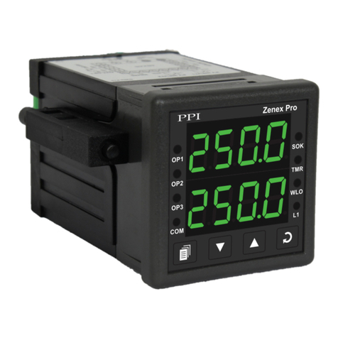
PPI Zenex-ultra User manual

Ultra Precision (0.01 °C) Self-Tune PID
Temperature Controller with
Programmable Timer
User Manual
Zenex-ultra

CONTENTS
User Manual
Zenex-ultra
1. FRONT PANEL LAYOUT 1
2. BASIC OPERATION 2
3. 3PAGES & PARAMETERS
4. INSTALLATION PARAMETERS 5
5. CONFIGURATION PARAMETERS 6
6. SUPERVISORY PARAMETERS 7
7. OP-2 FUNCTION PARAMETERS 8
8. OP-3 FUNCTION PARAMETERS 10
9. 11PID CONTROL PARAMETERS
10. HARDWARE ASSEMBLY AND CONFIGURATION 13
11. MECHANICAL INSTALLATION 19
12. ELECTRICAL CONNECTIONS 21

1
Table 1.1
Section 1
READOUTS
The upper readout is a 4 digit, 7-segment bright red LED display and usually displays the PV (Process Value) in 0.01 °C
Resolution. In parameter set-up mode, the upper readout displays parameter values.
The lower readout is a 4 digit, 7-segment bright green LED display and usually displays the SP (Process Setpoint) value in
0.01 Resolution. In parameter set-up mode, the lower readout displays prompts for the parameters.°C
INDICATORS
The Table 1.1 lists each front panel LED and the associated status.
The controller front panel comprises of digital readouts, LED indicators and membrane keys as shown in Figure 1.1 below.
User Manual
Zenex-ultra
FRONT PANEL LAYOUT
Figure 1.1
PPI
zenex-ultra
OP1 OP2 OP3
Upper Readout
Lower Readout
OP-3 Indicator
ENTER Key
UP Key
DOWN Key
PAGE Key
OP-1 Indicator
OP-2 Indicator
S
T
Soak Status Indicator
Balance Soak
Time Indicator
Status
Indicator
S
TGlows while the Lower Readout shows the Balance Soak Time in Main display
mode.
• Flashes while the Soak Timer is counting down.
• Glows steadily while the Soak Timer is outside the Timer Start Band or Hold
Band (that is, HOLD state).
• Indicates Output-1 ON/OFF status if the Control Output is Relay or SSR drive.
• Remains OFF if the Control Output is DC Linear.
OP1
• Indicates Output-2 status if OP2 function is Auxiliary / Blower Control.
• Flashes Alarm-1 status if OP2 function is Alarm.
OP2
OP3 • Indicates Output-3 status if OP3 function is Auxiliary Control.
• Flashes Alarm-2 status if OP3 function is Alarm.

2
BASIC OPERATIONS
MAIN DISPLAY MODE
After the power-up display sequence, the upper readout starts showing the measured PV (Process Value) and the lower
readout displays the SP (Setpoint) in 0.01°C Resolution.
This is called the MAIN display mode and this is the one that shall be used most often. The MAIN display mode is depicted in
Figure 2.1.
Figure 2.1
PV ERROR INDICATIONS
In case the PV falls below the Minimum Range or rises above the Maximum Range specified for the RTD Pt100 input type or in
case the RTD Pt100 sensor is open / broken; the upper readout flashes the error messages listed in Table 2.1 below. The
Figure 2.2 illustrates an open sensor condition.
Message PV Error Type
Over-range
(PV above Max. Range)
Under-range
(PV below Min. Range)
Open
(Sensor open / broken)
Table 2.1
User Manual
Zenex-ultra
Section 2
PV
SP
PPI
zenex-ultra
OP1 OP2 OP3
S
T
Figure 2.2
PPI
zenex-ultra
OP1 OP2 OP3
S
T

3
ORGANIZATION
The controller requires various user settings that determine how the controller will function or operate. These settings are
called parameters. The various parameters have been grouped as shown in Table 3.1. Each group is assigned a unique PAGE
NUMBER for its access and the parameters within each group are presented depending on the function(s) selected.
The parameters are always presented in a fixed format: The lower readout displays the parameter prompt (Identification Tag)
and the upper readout displays the set value. The parameters appear in the same sequence as listed in their respective
sections.
PAGES & PARAMETERS
Table 3.1
Group Page
Number Main Parameters
Installation
Parameters
Configuration
Parameters
Supervisory
Parameters
Output-2
Function
Output-3
Function
10
11
12
13
14
Output Type
Calibration Offset
Control Mode
Overshoot Inhibit
Control Logic
Hysteresis
Digital Filter
Serial Communication
Setpoint Locking
Tune At Setpoint Change
Optimize Command
Function Selection
Process Alarm Settings
Blower Settings
Soak Timer Settings
Function Selection
Process Alarm Settings
Heater Break Alarm
Serial Communication
PID Control
Parameters
Proportional Band
Integral Time
Derivative Time
15
ADJUSTING PARAMETER VALUES
Once a PAGE is accessed, step through the following sequence to adjust the values of the desired parameters:
1. Press and release the ENTER key until the prompt for the required parameter appears in the lower readout. The last
parameter in the list rolls back to the first parameter.
2. Use UP / DOWN keys to adjust the parameter value.
Note that some parameters (examples; Alarm Setpoint, Blower Setpoint, etc.) have numeric values while others
User Manual
Zenex-ultra
Section 3

4
(examples; Control Mode, Alarm Logic, etc.) have a series of options. If adjusting a numeric value; depressing the
UP/DOWN key once, increases/decreases the parameters value by one digit. For parameters having a series of options,
depressing the UP/DOWN key once takes you to the next/previous option. In each case, keeping the UP/DOWN key
pressed speeds up the rate. If the value reaches the maximum / minimum settable value/option, the upper readout flashes
and the UP (if maximum value is reached) or DOWN (if minimum value is reached) key has no effect.
3. Press and release the ENTER key. The new value gets stored in the controller's non-volatile memory and the next
parameter in the list is displayed.
The Figure 3.2 illustrates the example of altering the value for the parameter 'Control Output Type'. As in this example no other
parameter is available in the list, pressing ENTER key will not displayed any other parameter in the list.
Figure 3.2
To exit the set-up mode and return to the MAIN display, press and release PAGE key.
VIEW-ONLY PARAMETERS
While the controller is operating in the PID control mode, the user can view (but not adjust) the instantaneous values of the %
output power. The view facility is available in PAGE-0 and can be availed as described below.
1. Press and release PAGE key. The lower readout shows PAGE and the upper readout shows 0.
2. Press and release ENTER key. The controller enters into view mode.
3. Keep pressing ENTER key to select between the parameters available for viewing.
The prompt for identifying the parameter is indicated in the lower readout and the actual value is indicated in the upper
readout.
To exit view mode and return to the MAIN display mode; press and release PAGE key.
User Manual
Zenex-ultra
Prompt Parameter
% Output Power

5
The installation parameters are contained in PAGE-10 and are required to be set only at the time of a new installation.
The installation parameters are listed below in Table 4.1, followed by the definitions for each parameter.
INSTALLATION PARAMETERS
Table 4.1
Settings
(Default Value)
Parameter Description
OUTPUT TYPE
The controller is supplied with built-in Relay and DC voltage
pulses (for driving external SSR) as control output signals. The
required output type can be selected by appropriate jumper
settings as described in section 9: Hardware Assembly And
Configurations. The jumper-selected output type must also be set
as a value for this parameter for correct operation. The controller
automatically sets the cycle time for the time-proportioning PID
output in accordance with the selected output type. The Table 4.3
below lists the options available for setting this parameter value.
Refer Table 4.2
(Default : SSR)
Table 4.2
Option What it means Cycle Time
Electromechanical Relay contacts
(Common & Normally Open)
DC voltage pulses for driving
external Solid State Relay (SSR)
20 Seconds
1 Second
Note:
In the zenex-ultra, the Temperature Range is restricted to -19.99 to +102.9°C. This Temperature Range is fixed and not available as settable
parameter. The 0.01°C Resolution is available upto 99.99°C. After this, the resolution automatically changes to 0.1°C.
User Manual
Zenex-ultra
Section 4

6
The Configuration parameters are contained in PAGE-11 and are factory set to the appropriate default values. However, for
specific installations the user may need to alter the values. Altering the configuration parameter values affect either the
measured PV and/or the control algorithm implemented by the controller. The parameters are listed in Table 5.1 below,
followed by their definitions.
CONFIGURATION PARAMETERS
Table 5.1
Settings
(Default Value)
Parameter Description
-19.99 to +25.00
(Default : 0.00)
Enable
Disable
(Default : Enable)
Reverse
Direct
(Default : Reverse)
User Manual
Zenex-ultra
CONTROL LOGIC
Select Reverse (heat logic) or Direct (cool logic).
OVERSHOOT INHIBIT
(Available for PID control only)
Enabling this feature controls the PV rise or fall upon process
start-up in order to reach the control setpoint with as minimum
overshoot as possible.
CALIBRATION OFFSET
This value is algebraically added to the measured PV to derive the
final PV that is displayed and compared for alarm / control.
Final PV = Measured PV + Offset
CONTROL MODE
Select appropriate Control Algorithm suited for process
requirement.
(Default : PID)
On-Off
PID
0.10 to 25.00
(Default : 0.20)
1.0 to 25.0 Seconds
in steps of 0.5 Seconds
(Default :1.5)
HYSTERESIS
(Available for On-Off or Pulsed On-Off Control only)
Sets differential (dead) band between On-Off switching for OP1.
DIGITAL FILTER FOR PV
Sets the time constant, in seconds, for the low-pass digital filter
applied to the measured PV. The filter helps smoothing /
averaging the signal input and removing the undesired noise.
Note:
The Calibration Offset and Hysterisis parameter values are settable same as that for the PV resolution. Hence, they are also available in
0.01°C resolution. Their settings and default values are modified as per the 0.01°C resolution as shown in the above Table 5.1.
Section 5

7
The Supervisory parameters are available in PAGE-12 and provides communication parameters to the user and also can be
used to exercise control over operator level or to use the controller's in-built ability to improve upon the control performance
under conditions that are beyond the self-detection capabilities of the controller.
The parameters are listed in Table 6.1 below followed by their definitions.
SUPERVISORY PARAMETERS
Table 6.1
Settings
(Default Value)
Parameter Description
This parameter defines the communication speed expressed in
“Bits per Second”. This parameter is settable as 1200, 2400, 4800
or 9600 and must be set in accordance with the communication
speed set for the Master Device.
BAUD RATE
4800
9600
1200
2400
(Default : 4800 )
CONTROLLER ID NUMBER
This parameter, settable from 1 to 8, assigns a unique slave
identity number to the controller that the Master Device uses to
address the controller for data read/write operation.
1 to 8
(Default : 1)
SETPOINT LOCKING
Set to Yes to Lock the SP editing on the Lower Readout.
No
Yes
(Default : No)
SELF-TUNE ON SETPOINT CHANGE
The controller's “X-THERM” algorithm is powered with the ability
to self-detect the need for Tuning / Optimization of the controller if
there is a substantial change in the SP by the user. The algorithm
takes into account the magnitude of SP change and the
Temperature Range. If this parameter is set to ‘Enable’, the
controller, if required, automatically optimizes the control
parameter values while approaching the new SP. The user can set
this parameter to ‘Disable’ if this feature is not desired.
No
Yes
(Default : No)
User Manual
Zenex-ultra
Enable
Disable
(Default : Disable)
OPTIMIZE COMMAND
(Available for PID control only)
Set to ‘Yes’ to initiate a new tuning cycle or set to ‘No’ to abort a
tuning operation in progress.
Section 6

8
The Output-2 Function Parameters are available in PAGE-13. The parameters are specified in Table 7.1 below.
OP-2 FUNCTION PARAMETERS
Table 7.1
User Manual
Zenex-ultra
Settings
(Default Value)
Parameter Description
Process Low
Process High
Deviation Band
Window Band
Default : Process Low
(Default : 0.00)
0.00 to 99.99
-19.99 to +25.00
(Default : 0.00)
0.30 to +25.00
(Default : 0.30)
ALARM TYPE
Select the Alarm-1 activation type. Selecting ‘None’ will disable
the alarm and suppress all the related parameters for Alarm-1.
ALARM SETPOINT
(Available for Process High or Process Low Alarm-1 Type)
Sets Alarm limit independent of control setpoint.
DEVIATION BAND
(Available for Deviation Band Alarm-1 Type)
Sets positive or negative deviation (offset) limit from control
setpoint for High or Low Alarm-1 activation, respectively.
WINDOW BAND
(Available for Window Band Alarm-1 Type)
Sets symmetrical positive and negative deviation (offset) limits
from control setpoint for both High and Low Alarm-1 activation.
No
Yes
(Default : Yes)
Reverse
Direct
(Default : Direct)
ALARM INHIBIT
Set to Yes to suppress Alarm-1 activation upon power-up or
process start-up.
ALARM LOGIC
(Available if OP2 function is Alarm)
Select ‘Direct’ if Alarm-1 is to activate an Audio / Visual alarm.
Select ‘Reverse’ if Alarm-1 is to Trip the system.
Section 7

9
User Manual
Zenex-ultra
BLOWER FUNCTION AND PARAMETERS
The blower on-off operation is depicted in Figure 7.3 below.
PV
Blower ON
SP
Hysteresis Band
Blower Setpoint
Figure 7.3
The Blower Setpoint is set as a positive offset to the process setpoint SP. The Blower is switched ON if the PV equals or
exceeds the setpoint. The Blower is switched OFF when the PV falls below the setpoint by the value set by the Hysteresis
Band. The parameters for the Blower operations are listed in Table 7.3 below, followed by the definitions.
Table 7.3
Settings
(Default Value)
Parameter Description
0.00 to 25.00
(Default : 0.00)
0.10 to 25.00
(Default : 0.20)
BLOWER SETPOINT
(Available if OP2 function is Blower Control)
This parameter value is algebraically added to the Control SP to
obtain the setpoint value for the Blower Control. Can be set as
positive value or negative value.
Blower Control Setpoint = Control Setpoint (SP) + Offset Value
BLOWER HYSTERESIS
(Available if OP2 function is Blower Control)
Differential (dead) band between the blower ON and OFF states.

10
OP-3 FUNCTION PARAMETERS
The Output-3 Function Parameters are available in PAGE-14. The parameters are specified in Table 8.1 below.
Settings
(Default Value)
Parameter Description
0.00 to 99.99
(Default : 0.00)
-19.99 to +25.00
(Default : 0.00)
User Manual
Zenex-ultra
Table 8
Process Low
Process High
Deviation Band
Window Band
Default : Process Low
None
Alarm
(Default : None)
OUTPUT-3 FUNCTION
(Applicable for OP3 hardware module, if fitted)
Select the function / feature to which the OP3 module is to be
logically attached for activation.
ALARM TYPE
(Available if OP3 function is Alarm)
Select the Alarm-1 activation type. Selecting ‘None’ will disable
the alarm and suppress all the related parameters for Alarm-1.
ALARM SETPOINT
(Available for Process High or Process Low Alarm-1 Type)
Sets Alarm limit independent of control setpoint.
DEVIATION BAND
(Available for Deviation Band Alarm-1 Type)
Sets positive or negative deviation (offset) limit from control
setpoint for High or Low Alarm-1 activation, respectively.
WINDOW BAND
(Available for Window Band Alarm-1 Type)
Sets symmetrical positive and negative deviation (offset) limits
from control setpoint for both High and Low Alarm-1 activation.
ALARM INHIBIT
(Available if OP3 function is Alarm)
Set to Yes to suppress Alarm-1 activation upon power-up or
process start-up.
ALARM LOGIC
(Available if OP3 function is Alarm)
Select ‘Direct’ if Alarm-1 is to activate an Audio / Visual alarm.
Select ‘Reverse’ if Alarm-1 is to Trip the system.
Reverse
Direct
(Default : Direct)
Enable
Disable
(Default : Disable)
0.30 to 25.00
(Default : 0.30)
Section 8

11
As described in Section 5: Configuration Parameters, the control mode can be set as ON-OFF or PID. If set as PID, the
controller allows adjustment of various control related parameters that are grouped in PAGE-15. Note that these parameters
are not presented to the user if the set control mode is ON-OFF.
The PID control parameters are listed in Table 9.1 below, followed by their definitions.
PID CONTROL PARAMETERS
Table 9.1
Settings
(Default Value)
Parameter Description
This parameter, expressed in seconds, is applicable only to the
time proportion output associated with Relay or SSR as the
control output. For the time proportion output, the controller
implements the output power by adjusting the ON time of
Relay/SSR as a % of the Cycle Time. The Relay/SSR remains
OFF for the rest of the Cycle Time. For example, if the Cycle Time
is set to 20.0 seconds and if the output power demand is 10%, the
ON and OFF time duration for relay/SSR are computed (and
implemented) as follows:
ON time = 10% X 20 = (10/100) X 20 = 2 Seconds
OFF time = Cycle Time - ON duration = 20 - 2 = 18 Seconds
The Cycle Time, thus, equals 'ON time + OFF time'. The controller
output is 100% (fully on) during ON time and 0% (fully off) during
OFF time.
CYCLE TIME
0.5 to 120.0 Seconds
(in steps of 0.5 secs.)
(Default :
20 sec for relay,
1 sec for SSR)
0.01 to 99.99°C
(Default : )10.00°C
PROPORTIONAL BAND
This parameter value defines the band within which the control
output signal varies proportionally between the maximum (100%)
to the minimum (0%) level depending upon the error (difference
between the control setpoint and PV).
The Proportional Band is expressed in same resolution and unit
as that for PV and accordingly modified to set within 0.01 to 99.99
°C. Though this parameter value is automatically set by the self-
tune / optimize utility, the user can alter the value manually.
INTEGRAL TIME
This parameter value, expressed in seconds, is a measure of the
time response of the process and defines the time the controller
takes to remove the steady state offset errors within the
proportional band. Though this parameter value is automatically
set by the self-tune / optimize utility, the user can alter the value
manually. Setting this parameter value to 0 cuts-off the integral
action.
0 to 1000 Seconds
(Default : 100 Sec)
User Manual
Zenex-ultra
Section 9

12
User Manual
Zenex-ultra
(Default : 25 Sec)
0 to 250 Seconds
Settings
(Default Value)
Parameter Description
This parameter value, expressed in seconds, defines how strong
the control output level will change in response to the rate of
change of measured PV. This, in effect, produces larger
proportional and Integral actions should the PV change at a faster
rate. Though this parameter value is automatically set by the self-
tune / optimize utility, the user can alter the value manually. Setting
this parameter value to 0 cuts-off the derivative action.
DERIVATIVE TIME

13
User Manual
Zenex-ultra
HARDWARE ASSEMBLY AND CONFIGURATIONS
The Figure 10.1 above shows the indicator outer-case viewed with front label upright.
ELECTRONIC ASSEMBLY
The basic electronics assembly (without any plug-in modules), comprises of 3 Printed Circuit Boards (PCB). When viewed
from the front; the CPU PCB is to the right, Power-supply PCB is to the left and the Display PCB is behind the bezel.
The electronic assembly can be removed from the plastic enclosure and placed back as described and illustrated in Figure
10.2.
Figure 10.1
Section 10
UP
UP
Front Label
Pullout Grip
Enclosure
Connection Diagram
Rear Terminals
Ventilations
Ratchets
Panel Mounting Clamp
Panel Sealing
Gasket
Bezel
neuro 102
1
2
3
4
5
678910
11
12
13
14
15
16
17
18
N/O
C
+
-
REL AY
SSR / DC Linear
OUTPUT 1
Pt100
T/C
mV, V, mA
INPUT
OUTPUT 2
+
SSR / DC Linear
RELAY
N/O
N/C
C
OUTPUT 3
SERIAL
COMMS.
+
SSR / DC Linear
RELAY
N/O
N/C
C
PPI
L
N
AC
DC
SUPPLY
GND
A
B
AUXILIARY SP
SELECTION
PPI
zenex-ultra
OP1 OP3
S
T
OP2

14
User Manual
Zenex-ultra
Removing Assembly from Enclosure
With the indicator upright, hold the Bezel with the fingers on the pullout grips provided on the left and right sides of the bezel.
Pull the bezel outward. The assembly comes out with the bezel.
Placing Assembly Back into Enclosure
With the indicator upright (the UP inscribed on the Enclosure is on the topside), insert the bezel gently with the boards on either
side sliding into the guides provided inside of the Enclosure. Ensure that the bezel fits in tight on the Enclosure-front to secure
the panel-sealing gasket.
Figure 10.2
Power Supply
PCB
CPU PCB
Display
PCB
‘UP’ inscribed on topside
UP
UP
Placing Back
Removal
Pullout Grip
PPI
zenex-ultra
OP1 OP3
neuro 102
1
2
3
4
5
678910
11
12
13
14
15
16
17
18
N/O
C
+
-
RE LAY
SSR / DC Linear
OUTPUT 1
Pt100
T/C
mV, V, mA
INPUT
OUTPUT 2
+
SSR / DC Linear
RELAY
N/O
N/C
C
OUTPUT 3
SERIAL
COMMS.
+
SSR / DC Linear
RELAY
N/O
N/C
C
PPI
L
N
AC
DC
SUPPLY
GND
A
B
AUXILIARY SP
SELECTION
S
T
OP2

15
User Manual
Zenex-ultra
Figure 10.3
INPUT : Jumper Settings
The Input type is user configurable and thus requires, besides parameter selections, proper jumper-settings prior to electrical
connections. The jumper settings are provided in the form of Pins & Shorting-Link arrangements on the CPU PCB towards the
rear end as shown in Figure 10.3.
The Jumper setting marked A is for Input configuration. (Jumper settings marked B & C are unused.) For DC Linear Current
Inputs (0-20mA or 4-20mA), short the Pins using Shorting-Link. For all other Input types, keep the Shorting-Link parked
leaving the Pins open.
MOUNTING PLUG-IN MODULES
The indicator supports up to 3 plug-in modules, viz. Output-2 Module (Relay/SSR), Output-3 Module (Relay/SSR) and Option
Module (RS485 Serial Port or Remote Alarm Acknowledgment). These modules are either pre-fitted while the indicator is
shipped from the factory or can be fitted by the user later.
All 3 plug-in modules are provided with female socket that directly fits into the corresponding male plug provided on either
Power-supply PCB or CPU PCB. The Output-2 and Option Modules fit into plugs provided on Power-supply PCB whereas the
Output-3 Module fits into plug provided on the CPU PCB
OUTPUT-2 & OUTPUT-3 : Modules and Jumper Settings
The Output-2 and Output-3 Modules are identical and, thus, can be fitted interchangeably in Output-2 or Output-3 positions.
These modules can be configured for either Relay or SSR output through proper jumper selection. Two jumper settings A and
B, as shown in Figure 10.4, are required for Relay or SSR selection. Refer Table 10.1 for appropriate jumper setting positions.
CPU PCB
Pins Shorting
Link
1 2 3
BC
1234
PPI
zenex-ultra
}
}
BA
C

16
User Manual
Zenex-ultra
B
A
Relay/SSR Module
Table 10.1
Relay
SSR
1
2
3
1
2
3
1
2
3
1
2
3
Output Type Jumper Setting - A Jumper Setting - B
MOUNTING / UN-MOUNTING OF MODULES
The Figures 10.5 & 10.6 illustrates how to mount the plug-in Output-2 & Output-3 module, respectively. Notice the orientation
of the indicator and a few identifying components shown in figures to help locate the plugs for the modules. Ensure that the
socket snap-fits into the plug and the 2 projected parts on the module fit into the 2 slots provided on the Power-Supply / CPU
PCB for proper electrical contacts and secured fitting.
For plugging out the module(s), follow the steps below:
1. Gently pull apart the Power-supply board and the CPU board until the projections of the module board come out of the
slots.
2. Pull the module outward to unlock the socket from the plug.
Figure 10.4

17
User Manual
Zenex-ultra
Figure 10.5
Figure 10.6
Mounting Output-2 Module
PPI
Plug & Socket
Connector
Projected
Parts
Slots
Output
Module
Power Supply Board
Front Label Upright
zenex-ultra
Mounting Output-3 Module
Output
Module
Projections
PPI
Plug & Socket
Connector
Slots
CPU Board
Front Label
Upside-down
zenex-ultra

18
User Manual
Zenex-ultra
The plug for the Serial Communication or Remote Alarm Acknowledgment module is located on the Power-supply PCB. The
Figure 10.7 below illustrates how to plug-in the Serial Communication/Remote Alarm Acknowledgment module. To plug (or
unplug) the module simply insert (or remove) the socket into (or from) the plug.
Figure 10.7
Mounting Serial Communication/
Remote Alarm Acknowledgment Module
PPI
Plug & Socket
Connectors
Serial Communication/
Auxiliary SP Selection
Module
Power Supply Board
Front Label
Upside-down
zenex-ultra
Table of contents
Other PPI Temperature Controllers manuals
Popular Temperature Controllers manuals by other brands
American Standard
American Standard ACONT401AN21MA Installer's guide
Johnson Controls
Johnson Controls TE-631xM installation instructions
AKO
AKO 16523 quick guide
HANYOUNG NUX
HANYOUNG NUX TD510 Series Operation manual
Multitech
Multitech REVEAL RBS305-ATH user guide
samlexsolar
samlexsolar DC-BTS-A-C owner's manual
