BUSCH COBRA PLUS User manual

Get technical data,
instruction manuals,
service kits
COBRA PLUS
Dry Screw Vacuum Pumps
NX 0950 A PLUS
Instruction Manual
0870232499 | -0002_en-US | Original instructions 3/21/2023

Table of Contents
2 | 88 Instruction Manual COBRA NX 0950 A PLUS_EN_en
Table of Contents
1 Safety ..................................................................................................................................................................... 4
2 Product Description ............................................................................................................................................. 5
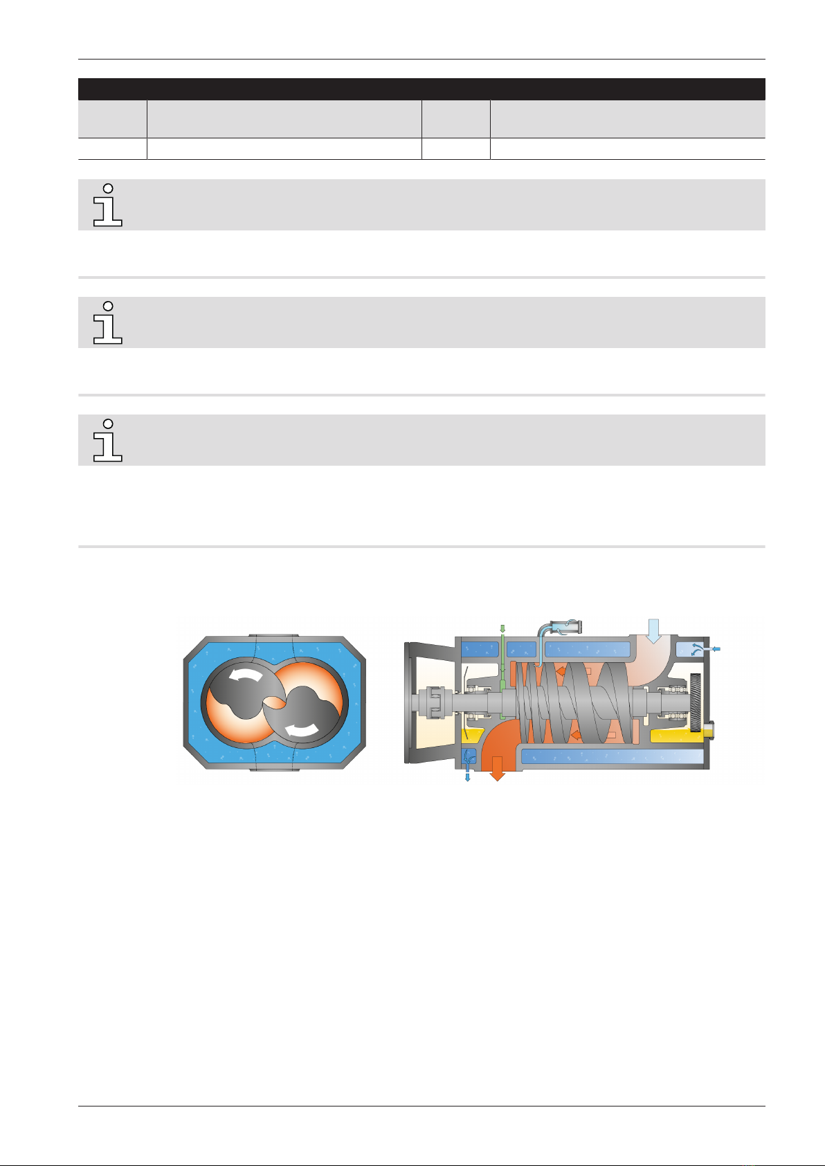
2.1 Operating Principle............................................................................................................................................. 7
2.2 Intended Use ....................................................................................................................................................... 8
2.3 Standard Features............................................................................................................................................... 8
2.3.1 User Interface ....................................................................................................................................... 8
2.3.2 Acoustic Cabinet ................................................................................................................................... 8
2.3.3 Control Unit........................................................................................................................................... 8
2.3.4 Monitoring Devices .............................................................................................................................. 9
2.3.5 I/O and Communication Port.............................................................................................................. 9
2.3.6 Gas Ballast Valve................................................................................................................................... 9
2.3.7 Inlet Check Valve .................................................................................................................................. 9
2.3.8 Water Cooling ....................................................................................................................................... 9
2.3.9 Sealing Systems .................................................................................................................................... 9
2.3.10 Silencer .................................................................................................................................................. 10
2.3.11 Barrier Gas System............................................................................................................................... 10
2.3.12 Oil Level Switches ................................................................................................................................. 10
2.3.13 Exhaust Pressure Sensor..................................................................................................................... 10
2.4 P&ID "Piping and Instrumentation Diagram" ................................................................................................. 10
2.5 LED Indicators...................................................................................................................................................... 11
2.6 Description of User Interface Functions .......................................................................................................... 11
2.6.1 Menu Overview..................................................................................................................................... 12
2.6.2 Bottom Bar ............................................................................................................................................ 12
2.6.3 Navigation ............................................................................................................................................. 13
2.6.4 Roles and Users .................................................................................................................................... 13
2.6.5 System Settings .................................................................................................................................... 15
2.6.6 Machine and Software Identification................................................................................................. 16
2.6.7 Ethernet Settings.................................................................................................................................. 16
2.7 Web Visualization ................................................................................................................................................ 17
3 Transport............................................................................................................................................................... 21
4 Storage................................................................................................................................................................... 23
5 Installation............................................................................................................................................................ 24
5.1 Installation Conditions ....................................................................................................................................... 24
5.2 Connecting Lines / Pipes .................................................................................................................................... 25
5.2.1 Suction Connection .............................................................................................................................. 25
5.2.2 Discharge Connection.......................................................................................................................... 26
5.2.3 External Inlet Pressure Sensor ........................................................................................................... 26
5.2.4 Cooling Water Connection .................................................................................................................. 27
5.2.5 Barrier Gas System Connection.......................................................................................................... 28
5.3 Filling Oil............................................................................................................................................................... 29
5.4 Gas Ballast Opening and Closing...................................................................................................................... 31
6 Electrical Connection ........................................................................................................................................... 32
6.1 PLUS Machine ...................................................................................................................................................... 32
6.2 Wiring Diagram Control Unit............................................................................................................................. 34
7 Commissioning ..................................................................................................................................................... 36
7.1 Prerequisites Before Use.................................................................................................................................... 36
7.2 Configuration....................................................................................................................................................... 37
7.3 Start Up................................................................................................................................................................. 38
8 In Operation.......................................................................................................................................................... 40

Table of Contents
Instruction Manual COBRA NX 0950 A PLUS_EN_en 3 | 88
8.1 Control Mode....................................................................................................................................................... 40
8.1.1 Local/Manual......................................................................................................................................... 41
8.1.2 Local/Auto "Week Planner" ................................................................................................................. 41
8.1.3 Remote/Auto......................................................................................................................................... 42
8.2 Operating Mode .................................................................................................................................................. 43
8.2.1 Speed Control ....................................................................................................................................... 43
8.2.2 Pressure Control................................................................................................................................... 44
8.3 Ecomode............................................................................................................................................................... 45
8.4 Warm-up / Cool-down Modes............................................................................................................................ 46
8.4.1 Conveying Condensable Vapors......................................................................................................... 47
8.5 Inlet Valve Control............................................................................................................................................... 48
8.6 Vacuum Booster Control .................................................................................................................................... 50
8.7 Monitoring ........................................................................................................................................................... 52
8.7.1 Operating Information ........................................................................................................................ 52
8.7.2 Operating Data ..................................................................................................................................... 53
8.7.3 History.................................................................................................................................................... 55
8.7.4 Operating Curves ................................................................................................................................. 56
8.8 Dysfunction.......................................................................................................................................................... 57
8.8.1 Warnings and Alarms Thresholds ...................................................................................................... 57
8.8.2 Warning/Alarm Acknowledgment Procedure................................................................................... 59
8.9 Stop the Machine ................................................................................................................................................ 60
9 Maintenance ......................................................................................................................................................... 61
9.1 Maintenance Schedule ....................................................................................................................................... 62
9.2 Oil Level Inspection............................................................................................................................................. 64
9.3 Cleaning the Inlet Screen................................................................................................................................... 65
9.4 Cleaning the Gas Ballast Filter........................................................................................................................... 66
9.5 Cleaning the Silencer .......................................................................................................................................... 67
9.6 Oil Change............................................................................................................................................................ 70
9.7 Machine Cleaning................................................................................................................................................ 73
10 Overhaul ................................................................................................................................................................ 74
11 Decommissioning ................................................................................................................................................. 75
11.1 Dismantling and Disposal .................................................................................................................................. 75
12 Spare Parts ............................................................................................................................................................ 76
13 Troubleshooting ................................................................................................................................................... 77
14 Technical Data ...................................................................................................................................................... 81
15 Oil ........................................................................................................................................................................... 82
16 EU Declaration of Conformity ............................................................................................................................. 83
17 UK Declaration of Conformity............................................................................................................................. 84

1 | Safety
4 | 88 Instruction Manual COBRA NX 0950 A PLUS_EN_en
1 Safety
Prior to handling the machine, this instruction manual should be read and understood. If anything
needs to be clarified, please contact your Busch representative.
Read this manual carefully before use and keep for future reference.
This instruction manual remains valid as long as the customer does not change anything on the
product.
The machine is intended for industrial use. It must be handled only by technically trained personnel.
Always wear appropriate personal protective equipment in accordance with the local regulations.
The machine has been designed and manufactured according to state-of-the-art methods. Never-
theless, residual risks may remain, as described in the following chapters and in accordance with the
chapter Intended Use [➔8]. This instruction manual highlights potential hazards where appropri-
ate. Safety notes and warning messages are tagged with one of the keywords DANGER, WARNING,
CAUTION, NOTICE and NOTE as follows:
DANGER
... indicates an imminent dangerous situation that will result in death or serious injuries if not
prevented.
WARNING
... indicates a potentially dangerous situation that could result in death or serious injuries.
CAUTION
... indicates a potentially dangerous situation that could result in minor injuries.
NOTICE
... indicates a potentially dangerous situation that could result in damage to property.
NOTE
... indicates helpful tips and recommendations, as well as information for efficient and trou-
ble-free operation.

Product Description | 2
Instruction Manual COBRA NX 0950 A PLUS_EN_en 5 | 88
2 Product Description
INOUT
CU
VP
HMI PIL
CAO NP
ESSAILSSB
CAI
ACA
VG
CD
ACA
BGC CWICWOCF
PWS
LAN
PWS
Description
IN Suction connection (Inlet) OUT Discharge connection (Outlet)
ACA Acoustic cabinet AIL Alarm indicator light
BGC Barrier gas connection CAI Cooling air inlet
CAO Cooling air outlet CD Condensate drain
CF Cooling fan CU Control unit
CWI Cooling water inlet CWO Cooling water outlet
ESS Emergency stop switch HMI User interface (Human-Machine)
LAN Communication port (Modbus TCP/IP) NP Nameplate
PIL Power indicator light PWS Power supply (Cable gland)
SSB Start/Stop button VG Ventilation grid
VP Vacuum pump

2 | Product Description
6 | 88 Instruction Manual COBRA NX 0950 A PLUS_EN_en
Vacuum pump (VP)
EB
IN
PMR
BGR
SI
CWD
OSG
CWI
NP
MP
OUT
CD
BGV
LS2 MOT
PSA1
PSA2TSA LS1
MP
WV
WSA OFPOSG
IS
GB
OFP
CWO
BGC
BGM
ODV
BGF
Description
IN Suction connection (Inlet) OUT Discharge connection (Outlet)
BGC Barrier gas connection BGF Barrier gas flow meter
BGM Barrier gas manometer BGR Barrier gas pressure regulator
BGV Solenoid valve (Barrier gas) CD Condensate drain
CWD Cooling water drain plug CWI Cooling water inlet
CWO Cooling water outlet EB Eye bolt
GB Gas ballast valve IS Inlet screen
LS1 Level switch (Oil level motor side) LS2 Level switch (Oil level inlet side)
MOT Motor (Pump drive) MP Magnetic plug
NP Nameplate ODV Oil drain valve
OFP Oil fill plug OSG Oil sight glass
PMR Plug for manual rotation of rotors PSA1 Pressure transmitter (Inlet gas pressure)
PSA2 Pressure transmitter (Exhaust gas pressure
before silencer)
SI Silencer

Product Description | 2
Instruction Manual COBRA NX 0950 A PLUS_EN_en 7 | 88
Description
TSA Resistance thermometer (Pump tempera-
ture)
WSA Waterflow sensor (Cooling liquid)
WV Solenoid valve (Cooling water)
NOTE
Technical term.
In this instruction manual, we consider that the term ‘machine’ refers to the ‘vacuum pump’.
NOTE
Illustrations
In this instruction manual, the illustrations may differ from the machine appearance.
NOTE
Illustrations and displays of the Human-Machine Interface (HMI).
Some of the HMI illustrations which are shown in this manual are taken from the HMI display of the "R5 RA
0840 A PLUS" vacuum pump. Although they may differ slightly for the "COBRA NX 0950 A PLUS" vacuum pump,
the principles of using of the interface however are similar.
2.1 Operating Principle
The machine works on the one-stage, twin-screw pump principle.
Two screw rotors rotate inside the cylinder. The pumped medium is trapped between the cylinder
and screw chambers, compressed, and transported to the gas outlet. During the compression pro-
cess, the two screw rotors do not come into contact with each other or with the cylinder. There is no
need for a lubrication or an operating fluid in the compression chamber.

2 | Product Description
8 | 88 Instruction Manual COBRA NX 0950 A PLUS_EN_en
2.2 Intended Use
WARNING
In case of foreseeable misuse outside the intended use of the machine.
Risk of injuries!
Risk of damage to the machine!
Risk of damage to the environment!
●Make sure to follow all instructions described in this manual.
The machine is intended for the suction of air and other dry, non-aggressive, non-toxic and non-ex-
plosive gases.
Conveying of other media leads to an increased thermal and/or mechanical load on the machine
and is permissible only after a consultation with Busch.
The machine is intended for indoor placement in a non-potentially explosive environment.
The machine is capable of maintaining ultimate pressure, see Technical Data.
The machine is suitable for continuous operation.
Permitted environmental conditions, see Technical Data.
NOTICE
Chemical compatibility of the process gases with the machine component materials.
Risk of corrosion inside the compression chamber which can reduce performance and its life-
time!
●Check if the process gases are compatible with those following materials:
- Cast iron
- Steel
- Stainless Steel
- Aluminum
- Fluor elastomer (FKM/FPM)
●In doubt, please contact your Busch representative.
2.3 Standard Features
2.3.1 User Interface
A user interface, also termed human-machine interface (HMI), allows the control, monitoring and
configuration of the machine via a 7.5” touchscreen.
Further information in the chapter Description of User Interface Functions [➔11].
2.3.2 Acoustic Cabinet
Stylish and functional, the acoustic cabinet (ACA) significantly reduces the sound emitted by the vac-
uum pump.
2.3.3 Control Unit
The control unit is an electrical cabinet where a variable speed drive, a PLC and other electrical com-
ponents are integrated.
It also supplies the active cooling air with electrical current.
The power supply must be connected to it, see Electrical Connection.

Product Description | 2
Instruction Manual COBRA NX 0950 A PLUS_EN_en 9 | 88
2.3.4 Monitoring Devices
The machine is equipped with several monitoring devices to visualise the operating values, machine
conditions and to protect the machine from any severe damage.
The pump temperature, cooling water flow, oil level, inlet gas pressure and counter pressure at the
discharge can be displayed when the machine is running, see Monitoring [➔52]
Two signal levels are transmitted, a warning and an alarm/trip, see Dysfunction [➔57].
2.3.5 I/O and Communication Port
The control unit (CU) is equipped with a RJ45 (Modbus) communication port that can allow remote
control and monitoring of the machine.
●Refer to the specific document “Pump Control Instructions, art. no.: 0870213261” for more details
or contact your Busch representative.
2.3.6 Gas Ballast Valve
The gas ballast valve mixes the process gas with a limited quantity of ambient air to counteract the
condensation of vapor inside the machine.
The gas ballast valve has an influence on the ultimate pressure of the machine, see Technical Data.
2.3.7 Inlet Check Valve
In order to avoid reverse rotation after switching off, the machine is equipped with an inlet check
valve.
The inlet check valve also prevents fast venting of the connected vacuum system.
The inlet check valve is also equipped with a pressure sensor.
Pressure sensor range and accuracy
Range: 0-1600 mbar Accuracy: +/- 9.6 mbar
2
1
Description
1 Inlet Check Valve 2 Pressure sensor
2.3.8 Water Cooling
The machine is cooled by a cooling water circuit in the cylinder cover and cylinder.
2.3.9 Sealing Systems
The machine is equipped with labyrinth seals on the motor side and suction side.
Sealing systems prevent the process gas going to the bearings chambers.

2 | Product Description
10 | 88 Instruction Manual COBRA NX 0950 A PLUS_EN_en
Depending on the application, the sealing systems efficiency can be improved with a barrier gas sys-
tem, see Barrier Gas System [➔10].
2.3.10 Silencer
The silencer reduces the exhaust gas noise at the machine discharge (OUT).
2.3.11 Barrier Gas System
The barrier gas system allows the supply of compressed air or nitrogen into the motor side shaft
seals to improve the sealing efficiency.
2.3.12 Oil Level Switches
The machine is equipped with two oil level switches to monitor the oil levels at the motor and suc-
tion sides.
2.3.13 Exhaust Pressure Sensor
The machine is equipped with an exhaust pressure sensor to monitor the back pressure at the dis-
charge.
2.4 P&ID "Piping and Instrumentation Diagram"
1
2
2
Description
1 Cooling Water 2 Air
Description
IN Suction connection (Inlet) OUT Discharge connection (Outlet)
BGV Barrier gas solenoid valve CF Cooling Fan
CPL Coupling GB Gas ballast
LS1 Level switch “alarm/trip” (Oil level motor
side)
LS2 Level switch “alarm/trip” (Oil level inlet side)
MOT1 Motor (Pump drive) MOT2 Motor (Active system cooling)

Product Description | 2
Instruction Manual COBRA NX 0950 A PLUS_EN_en 11 | 88
Description
NRV Non-return valve (Not used as an isolation
valve)
PSA1 Pressure transmitter (Inlet gas pressure)
PSA2 Pressure transmitter (Exhaust gas pressure
before silencer)
TSA Resistance thermometer (Pump safety tem-
perature)
VP Vacuum pump WSA Water flow sensor (Cooling liquid)
WV Solenoid valve (Cooling water)
2.5 LED Indicators
Next to the user interface, there are three LEDs giving a visual indication of the state of machine.
1 2 3
Description
1 Start/stop button (SSB):
The LED is green when the machine is
running.
2 Power indicator light (PIL):
The LED is green when the machine is
powered.
3 Alarm indicator light (AIL):
The LED flashes in red when a warning
occurred.
The LED is continuously red when an
alarm occurred.
2.6 Description of User Interface Functions
The display is divided into three distinct parts.
1
2
3
Description
1 Menu tabs and sub-tabs 2 Information panel
3 Bottom bar

2 | Product Description
12 | 88 Instruction Manual COBRA NX 0950 A PLUS_EN_en
2.6.1 Menu Overview
The menu consists of four main tabs with their own sub-tabs:
●The "HOME" tab is the main display and is mainly useful for live monitoring.
●The “OPERATIONS” tab displays the operating parameters/modes and allows the control of the
machine.
●The “MAINTENANCE” tab displays the history of malfunctions, maintenance intervals and oper-
ating curves.
●The “SYSTEM” tab allows to set or change settings and provides information about the product
and its distributor.
2.6.2 Bottom Bar
The bottom bar provides different pieces of information, in particular the machine state and warn-
ing/alarm status.
1 3 5
76
2 4
Description
1 Machine state 2 Machine state: "OFF" or "RUNNING"
3 Warnings and alarms status 4 Status: "WARNING" or "ALARM"
5 Date and hour 6 Screen brightness
7 Help

Product Description | 2
Instruction Manual COBRA NX 0950 A PLUS_EN_en 13 | 88
2.6.3 Navigation
When several screens/pages are available in the information panel, dots representing the different
screens/pages and “PREVIOUS/NEXT” buttons are displayed above the bottom bar.
●Press either on a dot or “PREVIOUS/NEXT” button to pass from a screen/page to another.
The switch button is black when deactivated and orange when activated.
●Press on the switch button to change its state.
1
2
Description
1 Deactivated (Off) 2 Activated (On)
If a password is required:
●Enter the password, see the chapter Roles and Users [➔13].
When the character “>” is displayed in a cell of the information panel, that means a step further is
available. For example: a redirect link to another view or to open a specific editing view.
●Press in the cell to open the next dialog windows.
1
Description
1 Step further available, press to access
the next dialog window.
If a password is required:
●Enter the password, see the chapter Roles and Users [➔13].
2.6.4 Roles and Users
Three roles of user rights are predefined in the system.
Role 1 ► Operator
This role is intended for machine operators to control the machine (limited rights) or monitor oper-
ating values. It does not require any password.
Role 2 ► Installation/Maintenance technician
This role is intended for installation/maintenance technicians to configure the machine according to
the application. The password for this role can be found in the separate sheet attached to this in-
struction manual and allows an access to the following features:

2 | Product Description
14 | 88 Instruction Manual COBRA NX 0950 A PLUS_EN_en
●change operating mode,
●reset hours before the next service,
●set the remote control and monitoring parameters, refer to the specific document "Pump Con-
trol Instructions, art. no.: 0870213261".
Role 3 ► Busch Service
Only authorized personnel from Busch Service have this level of access rights.
NOTE
In case of any questions related to the machine settings:
●Please contact Busch Service.
When a password is required, the display shows the following screen:
●Press on the three stars.
●Enter the correct password in the number pad according to your access right.
●Press “Save”.
●From now on, the specific rights are open for a limited period ► delay of 5 minutes.

Product Description | 2
Instruction Manual COBRA NX 0950 A PLUS_EN_en 15 | 88
2.6.5 System Settings
●To edit the system settings such as date, time, language, and units:
●Go to “SYSTEM” > “SETTINGS”.
●Press on the value to change the selected data.
NOTE
Warnings and alarms thresholds
Thresholds can only be changed by Busch Service “Role 3”, see the predefined factory settings
in the chapter Warnings and Alarms Thresholds [➔57].
NOTE
Advanced settings
Advanced settings can only be changed by Busch Service “Role 3”, refer to the specific docu-
ment "Pump Control Instructions, art. no.: 0870213261".

2 | Product Description
16 | 88 Instruction Manual COBRA NX 0950 A PLUS_EN_en
2.6.6 Machine and Software Identification
To display the machine and software identification:
●Go to “SYSTEM” > “MODEL”.
2.6.7 Ethernet Settings
●To configure the ethernet settings according to your network:
●Go to “SYSTEM” > “ETHERNET”.
●Make sure that the Ethernet port (COM) on the right side of the control unit (CU) of the ma-
chine is connected to a computer or to the company network.
●Change the values on the right side of the screen (Change settings), password required ► Role
2, see Roles and Users [➔13].
●Press on the switch button to save the new settings.
NOTE
The current Ethernet values are displayed in the left side of the screen (Ethernet settings).
To change these values, it is necessary to fill in all the fields in the right side of the screen
(Change settings) before applying the changes by pressing on the switch button:
●New IP address
●New subnet mask
●New gateway
➔To change the Ethernet settings, it is recommended to connect the vacuum pump with the de-
sired equipment beforehand via the Ethernet port available on the right side of the control cab-
inet (LAN - see illustration in the chapter “Product Description” of the instruction manual of the
vacuum pump).

Product Description | 2
Instruction Manual COBRA NX 0950 A PLUS_EN_en 17 | 88
Description Default value
IP address 192.168.0.22
Subnet mask 255.255.255.0
Gateway 192.168.0.1
PLC port (0-65535) 502 (cannot be changed)
PLC Slave no. 247 (F7) (cannot be changed)
2.7 Web Visualization
Each machine has a built-in Web visualization interface, which allows remote monitoring of the main
operating parameters from a computer (via a LAN connection or via an optional WIFI connection), a
tablet or a smartphone (via an optional WIFI connection).
To use the Web visualization interface via a LAN connection:
●Connect an Ethernet cable to the Ethernet port (COM) on the right side of the control unit (CU) of
the machine.
●Connect the Ethernet cable to the company network or to the computer. To connect the Ethernet
cable to the computer, use a USB/LAN adapter or connect it directly to the Ethernet port of the
computer and use the internal network card (administrator access required).
●Check the ethernet settings of the machine in the “Ethernet Settings” menu of the User Interface
Display (HMI), see Ethernet Settings [➔16]. By default, the ethernet settings are:
●IP address: 192.168.0.22
●Subnet mask: 255.255.255.0
●Gateway: 192.168.0.1
●Check the ethernet settings of the computer network (Internet Protocol Version 4 (TCP/IPv4)
Properties). The Subnet mask and the first 3 bytes of the IP address must be the same as on the
PLUS machine.

2 | Product Description
18 | 88 Instruction Manual COBRA NX 0950 A PLUS_EN_en
●Open your web browser (full screen window) and type the IP address of the machine to monitor
in the address bar, followed by: :8080/smartpump.htm. By default, the whole address to be typed
in the web browser is: 192.168.0.22:8080/smartpump.htm
●When the Web visualization interface opens, select “Computer” as monitoring device.
NOTE
The following illustrations are taken from the web visualization of the "R5 RA 0840 A PLUS"
vacuum pump.
●The main screen, “Dashboard”, shows the main operating parameters and settings of the ma-
chine (machine status, operating mode, running hours, inlet pressure…).
●Use the icons in the bottom bar to navigate in the Web visualization interface.
●The second page “Service” shows the service table of the machine and Busch service contact in-
formation.

Product Description | 2
Instruction Manual COBRA NX 0950 A PLUS_EN_en 19 | 88
●The third page “My vacuum pump” gives general information about the machine.
●The fourth page "Operations" gives remote access to the basic settings of the vacuum pump:
Control mode, Operating mode, Ecomode, Week planner, Warm-up and Cool-down, Inlet valve
control, Vacuum booster control.
For more information about these settings, see chapter In Operation [➔40].

2 | Product Description
20 | 88 Instruction Manual COBRA NX 0950 A PLUS_EN_en
NOTE
Remote start/stop.
Remote start/stop of the vacuum pump is not possible via the Web Visualization interface.
NOTE
●Contact Busch:
➔If the Ethernet port of the machine (COM) is already used for remote control / monitoring
purpose.
OR
➔In order to use the Web visualization function via a WIFI connection (requires an optional
WIFI module).
●The Web visualization interface is optimized for Google Chrome.
●To change the IP address of the machine (in the event it is already used by another machine for
instance), go to the “Ethernet Settings” menu of the User Interface Display (HMI) on the machine,
see Ethernet Settings [➔16].
This manual suits for next models
1
Table of contents
Popular Laboratory Equipment manuals by other brands

Leica
Leica Viva GNSS Getting started guide

Thermo Scientific
Thermo Scientific NanoDrop Lite Plus user guide

Showa Denko
Showa Denko Shodex Shodex IC SI-36 4D Operation manual

Integra
Integra Cusa Excel manual

ExtractCraft
ExtractCraft EtOH Pro user guide

StarTech.com
StarTech.com POEINJ1G90W quick start guide

Biohit
Biohit mLINE m10 instruction manual

Radleys
Radleys Heat-On RR68000 instructions

Ametek
Ametek PARSTAT MC Hardware manual

Sartorius Stedim Biotech
Sartorius Stedim Biotech BIOSTAT CultiBag RM 600 operating manual

Scientifica
Scientifica Multiphoton Scanhead Setup and operation manual

JEOL
JEOL JEM1400 Operation