BUSCH VacTest User manual

Instruction Manual
VacTest
Vacuum Measurement Equipment
Mobile Gauge TTP 900
0870205880/-_en / Original instructions / Modifications reserved 09/11/2017
Busch Produktions GmbH
Schauinslandstraße 1, 79689 Maulburg
Germany

Table of Contents
2 / 20 0870205880_TTP900_-_IM_en
Table of Contents
1 Safety........................................................................................................................... 3
2 Product Description ..................................................................................................... 4
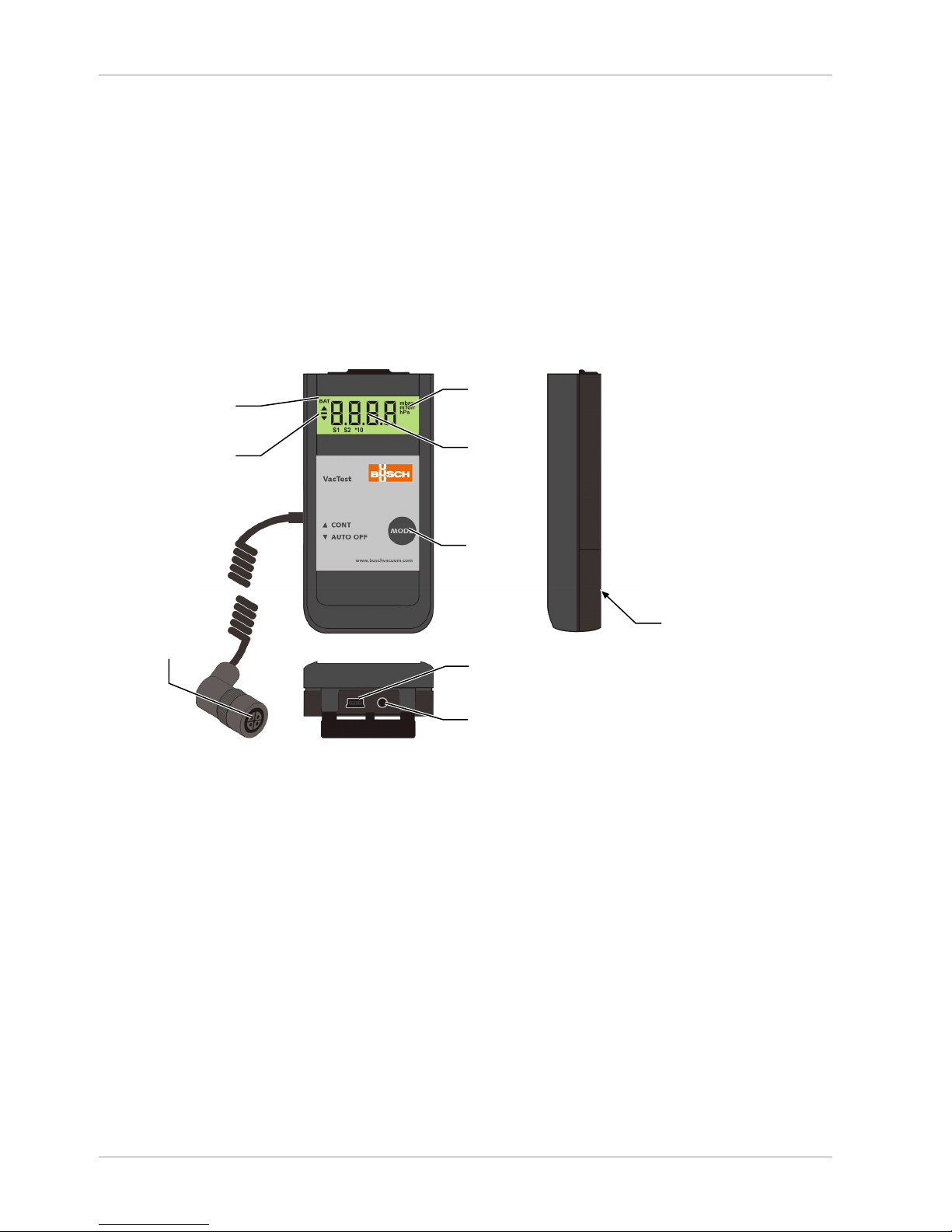
2.1 Interface Illustration.............................................................................................. 4
2.2 Product Identification ...........................................................................................4
2.3 Delivery Content ..................................................................................................4
2.4 Proper Use ........................................................................................................... 5
2.5 Improper Use ....................................................................................................... 5
3 Transport and Storage.................................................................................................. 5
4 Installation................................................................................................................... 5
4.1 Installation Conditions ..........................................................................................5
4.2 Sensor Connector .................................................................................................5
4.3 Vacuum Connection .............................................................................................6
4.4 Electrical Connection ............................................................................................7
4.4.1 Battery Operation......................................................................................7
4.4.2 Operation with External Power Supply.......................................................8
4.5 USB Interface........................................................................................................ 8
5 Operation .................................................................................................................... 9
5.1 Before Operation.................................................................................................. 9
5.2 Select Operating Mode......................................................................................... 9
5.3 Data Recording..................................................................................................... 9
5.4 Adjustment...........................................................................................................11
5.5 Pressure Units....................................................................................................... 13
5.6 Maximum Operation Time ...................................................................................13
5.7 Adjust Gas Correction Factor ................................................................................14
6 Communication ........................................................................................................... 15
6.1 PC Mode..............................................................................................................15
6.2 VacTest Explorer Software ....................................................................................15
7 Maintenance and Service ............................................................................................. 16
8 Troubleshooting........................................................................................................... 16
9 Accessories .................................................................................................................. 17
10 Technical Data ............................................................................................................. 17
10.1 Gas Correction Factor ...........................................................................................18
11 EU Declaration of Conformity ...................................................................................... 19

Safety | 1
0870205880_TTP900_-_IM_en 3 / 20
1 Safety
• Read and follow the instructions of this manual.
• Inform yourself regarding hazards, which can be caused by the product or arise in
your system.
• Comply with all safety instructions and regulations for accident prevention.
• Check regularly that all safety requirements are being complied with.
• Adhere to the applicable regulations and take the necessary precautions for the pro-
cess media used.
• Consider possible reactions between materials and process media.
• Consider possible reactions of the process media due to the heat generated by the
product.
• Before you start working, find out whether any of the vacuum components are con-
taminated.
• Adhere to the relevant regulations and take the necessary precautions when handling
contaminated parts.
• Communicate the safety instructions to other users.
This instruction manual highlights potential hazards where appropriate. Safety notes and
warning messages are tagged with one of the keywords DANGER, WARNING, CAU-
TION, NOTICE and NOTE as follows:
DANGER
... indicates an imminent dangerous situation that will result in death or serious injuries if
not prevented.
WARNING
... indicates a potentially dangerous situation that could result in death or serious injuries.
CAUTION
... indicates a potentially dangerous situation that could result in minor injuries.
NOTICE
... indicates a potentially dangerous situation that could result in damage to property.
NOTE
... indicates helpful tips and recommendations, as well as information for efficient and
trouble-free operation.

2 | Product Description
4 / 20 0870205880_TTP900_-_IM_en
2 Product Description
The mobile gauge TTP 900 is equipped with a Pirani sensor whose measurement prin-
ciple is based on the thermal conductivity of gases. The Pirani sensor provides indirect
pressure measurements which are dependent on the gas nature, see Adjust Gas Correc-
tion Factor [►14].
The gauge can also be operated under vacuum inside of a vacuum chamber.
Due to the integrated data recorder functionality it is possible to store up to 2000 meas-
urements in the vacuum gauge. By means of the USB interface you can transmit the
stored measurement data to a PC or record measurements online on PC as well.
2.1 Interface Illustration
Mode key
Pressure
unit
Pressure
display
Refresh: 1.0s
Change battery
display
Operation mode
USB interface
Connection for
mains adapter
12 V ; 50 mA ; jack 2.5 mm (+ at tip)
Battery compartment
cover
Sensor connector
2.2 Product Identification
The product model can be found on the product's nameplate. Technical modifications
are reserved without prior notification.
2.3 Delivery Content
Included in the delivery consignment are:
– Mobile gauge TTP 900
– Sensor head for TTP 900
– Protective cover
– 9 Volt block battery
– Instruction manual
Available accessories, consult the chapter Spare Parts and Accessories.

Transport and Storage | 3
0870205880_TTP900_-_IM_en 5 / 20
2.4 Proper Use
The TTP 900 serves exclusively to measure total pressure in a range of:
– 100…1 x 10⁻³ mbar.
2.5 Improper Use
The use for purposes not mentioned above is regarded as improper, especially:
– Connection to pumps or units which are not suitable for this purpose according
to their operating instructions.
– Connection to units which have exposed voltage-carrying parts.
– Operation of the devices in areas with ionizing radiation.
No liability or warranty will be accepted for claims arising from improper use.
3 Transport and Storage
• Check the device for transport damage.
NOTICE
Devices without external protection.
Risk of damage to the device!
• The device must not come into contact with electrostatically chargeable materials and
must not be moved within electrical or high magnetic fields.
If a storage is planned:
• Seal the vacuum flange with the protective cover.
• Comply with the storage temperatures, see technical data.
• In rooms with moist or aggressive atmospheres, the device must be airproof shrink-
wrapped in a plastic bag together with a bag a desiccant.
4 Installation
CAUTION
Unauthorized modifications.
Risk to injury!
• Modifications or conversions of the gauge are not allowed.
4.1 Installation Conditions
• Make sure that the environment of the device is not potentially explosive.
• Make sure that the ambient conditions comply with the Technical Data [►17].
4.2 Sensor Connector
• Plug at the end of the spiral cable the Pirani sensor head (ISO KF flange).

4 | Installation
6 / 20 0870205880_TTP900_-_IM_en
Connector:
Type Binder Series 713
4-pin, female
2 1
3 4
Pin Nr. Description
1 PTC (KTY110, 2 kΩ / 20°C)
2 PTC (KTY83-110, 1 kΩ / 20°C)
3 Filament
4 GND
4.3 Vacuum Connection
CAUTION
Unintended opening of clamp with an overpressure in the vacuum system over 1000
mbar.
Risk to injury!
Damage to your health!
• Parts may fly around.
• Unsecured hose connections can release process media.
CAUTION
Overpressure in the vacuum system over 1500 mbar
Damage to your health!
The elastomer washers cannot withstand the pressure and can release process media.
• Use sealing rings with an outer centering ring.
NOTICE
Dirt and damage at the vacuum flange.
Impair the function of the gauge!
• Make sure that the flange is clean, dry and free of grease.
• When handling the instrument, make sure that the flange is protected against dirt and
damage.
• Remove the protective cover (is required again during maintenance work!).
• Connect the flange to the system.
Connection size:
– ISO KF 16
• Make sure that the sensor flange is connected to the ground, when operated with ex-
ternal power supply.

Installation | 4
0870205880_TTP900_-_IM_en 7 / 20
4.4 Electrical Connection
4.4.1 Battery Operation
Before operating the gauge a suitable battery or rechargeable battery must be inserted.
• Pull the battery cover on the back of the unit downwards and insert the battery
• Close the cover again by pushing it upwards until it snaps into position.
Battery types:
– 9 Volt AlMn block battery type 6LR 61; lifetime max. 40 hours
– 9 Volt Lithium block battery; lifetime max. 100 hours.
NOTICE
Inferior or damage batteries may leak gas or liquid under vacuum.
Risk of damage to the gauge!
• If it is intended to expose the entire gauge to vacuum, seek confirmation from the
battery supplier that the battery is vacuum proof.
NOTE
Poor battery power is indicated by the ‘’BAT’’-prompt in the upper left corner of the dis-
play. Operation of the gauge is still possible. Once the battery is completely discharged,
the gauge switches off.
Rechargeable batteries have to be removed for charging. Please use suitable, commer-
cially available chargers.

4 | Installation
8 / 20 0870205880_TTP900_-_IM_en
4.4.2 Operation with External Power Supply
The gauge can be operated alternatively with an external 12V power supply. The socket
for the power supply is located behind the dust protection lid.
• Open the lid carefully and pull it out slightly.
1
2
1 = Jack plug 2.5 mm ; 12 … 15 VCD
2 = AGND
NOTE
The battery can be left in the gauge when the external power supply is used. A re-
chargeable battery will not be loaded but can remain in the gauge.
4.5 USB Interface
The USB port can be connected to a PC via VacTest explorer to read out stored measure-
ment data, transmit measurement values or configure the gauge.
Connector type:
Mini USB Type B
1 2 3 4 5
1 = VCC ; +5 V
2 = Data -
3 = Data +
4 = GND
5 = GND

Operation | 5
0870205880_TTP900_-_IM_en 9 / 20
5 Operation
NOTICE
Aggressive media such as fluorides, halogenides, carbon, oxygen plasma and all other
corrosive media.
Reduce sensor life-time!
• Furthermore, dust, oil or condensing vapours will affect sensor performance and may
cause malfunction.
5.1 Before Operation
Dependence On Gas Type
The measured pressure will depend on composition and type of gas. The gauge is factory
calibrated for N2 and dry air.
To adjust to other gases, a suitable correction factor for the Pirani sensor can be set in
the gauge for the pressure range below 0.5 mbar, see Adjust Gas Correction Factor
[►14].
5.2 Select Operating Mode
Short-Term Operation "Auto-Off" mode
• Press “Mode” key
MODE
mbar
The current pressure is displayed.
The gauge will automatically shut down after 20 seconds.
Continuous Operation "Cont" mode
Notes: Available only when data recorder function is disabled.
MODE
mbar
The current pressure is displayed.
MODE
mbar
If the “Cont" mode is activated, the gauge
is in continuous operation until it is
switched-off manually or, after the max-
imum operation time is reached.
5.3 Data Recording
To operate the gauge as a pressure display with data recorder functionality, activate the
recording function as described below.
Activate the data recording and configure the storage interval
In order to configure the storage interval, the gauge’s configuration mode must be ac-
tivated.
Starting condition: the gauge is switched off.
• Hold “Mode” key pressed for approx. 5 seconds, until the display shows ‘’rAtE’’.

5 | Operation
10 / 20 0870205880_TTP900_-_IM_en
MODE
5sec
After additional 5s the current rate setting for internal data recording is displayed and
can now be adjusted by means of the “Mode” key.
5sec
"off" : data recording is disabled.
MODE
"HiLo" means that only minimum and
maximum pressures are stored.
MODE
s
Save measurements every 1 s.
Other storage intervals: 2 s, 10 s, 1 min, 10
min
MODE
"trig" means that new measurement values
will only be recorded if the current value
differs from the last stored value by at least
2 digits (e.g. 2.3 … 2.5). This reduces the
data volume and optimally uses the storage
capacity of the gauge.
When data recording is active, minimum and maximum pressure are recorded simultan-
eously.
Without further keystroke the gauge is switched into "Auto-Off" mode after 5 seconds.
The last settings are saved.
NOTE
Via USB interface the user can set recording rates between 1.0 s and 6000 s. The record-
ing rate will stay available in the menu after "trig".
Stored Maximum Pressure
• Press “Mode” key until “Hi” is displayed.
MODE
mbar
2sec
After two seconds the stored maximum
pressure is displayed
Without further keystroke the gauge is switched into "Auto-Off" mode after 5 seconds.
Stored Minimum Pressure
• Press “Mode” key until “Lo” is displayed
MODE
2sec
mbar
After two seconds the stored minimum
pressure is displayed
Without further keystroke the gauge is switched into "Auto-Off" mode after 5 seconds.

Operation | 5
0870205880_TTP900_-_IM_en 11 / 20
Delete Memory
• Press “Mode” key until “cLr” is displayed
MODE
On further keystroke the stored Min-/Max-values as well as the data memory are de-
leted.
Without further keystroke the gauge is switched into "Auto-Off" mode after 5 seconds.
Data Recording
MODE
mbar
The current pressure is displayed. Measure-
ment values are stored according to the
configured storage interval.
The recording mode stops as soon as the gauge is full (max. of 2000 measurement val-
ues) or if the is shut down.
Quit Data Recording Mode
• Double keystroke: device switches into auto-off mode and will shut down automatic-
ally after approximately 10 seconds.
MODE
mbar
2x
MODE
5.4 Adjustment
The gauge is factory calibrated in upright position. Other orientations, different climatic
conditions, extreme temperature changes, ageing or contamination may necessitate re-
adjustment.
NOTE
Conduct adjustment at the same ambient temperature at which the device is typically
operated.
• Activate the configuration mode to perform the adjustment.
Starting condition: the gauge is switched off.
• Hold the “Mode” key pressed for approx. 5 seconds, until the display shows ‘’rAtE’’.
MODE
5sec
• Press the “Mode” key repeatedly until "CAL" is displayed.
MODE
Adjustment to Atmosphere Pressure
NOTE
Adjustment on atmosphere pressure is possible only if the current pressure is above 800
mbar. Otherwise adjustment is denied and the error message "Err" displayed.

5 | Operation
12 / 20 0870205880_TTP900_-_IM_en
5sec
• Confirm CAL.H by pressing the “Mode “key.
MODE
mbar
• Press the “Mode” key to adjust the reference value.
MODE
mbar
After 5s without further keystroke adjustment is performed.
5sec
Without further keystroke, the unit switches to "Auto-Off" mode after approx. 5
seconds.
Adjustment to Zero Pressure
NOTE
For adjustment on zero pressure the current pressure inside the sensor has to be less than
1 x 10⁻⁴ mbar.
The pressure reading must be less than 4 x 10⁻² mbar, otherwise adjustment is denied
and the error message "Err" displayed.
• Activate the configuration mode to perform the adjustment.
Starting condition: the gauge is switched off.
• Hold the “Mode” key pressed for approx. 5 seconds, until the display shows ‘’rAtE’’.
MODE
5sec
5sec
After 5 more seconds the display shows:
5sec
• Press “Mode” key to adjust the reference value.
MODE
During the adjustment procedure (approx.
20s) the display shows "CALI"
Without further keystroke, the unit switches to "Auto-Off" mode after approx. 5
seconds.

Operation | 5
0870205880_TTP900_-_IM_en 13 / 20
Calibration messages
mbar
Torr
If during the calibration, the message “Ur”
appears, it means that the adjustment has
been successfully achieved.
mbar
Torr
If during the calibration, the message “Err”
appears, it means that no adjustment was
performed.
5.5 Pressure Units
In order to change the pressure units, the gauge’s configuration mode must be activated.
Starting condition: the gauge is switched off.
• Hold the “Mode” key pressed for approx. 5 seconds, until the display shows ‘’rAtE’’.
MODE
5sec
• Press “Mode” key repeatedly until “unit” is displayed.
MODE
After 5 seconds the current unit setting is displayed:
5sec
mbar
• Within 10 s, select “mbar", "Torr" or "hPa" using the mode key
MODE
Torr
Without further keystroke, the unit switches to "Auto-Off" mode after approx. 5
seconds. The last settings are saved.
5.6 Maximum Operation Time
When operating continuously in “Cont” mode or “Data Recording” mode the unit stays
on, until the selected maximum operation time has elapsed.
In order to change this time, the gauge’s configuration mode must be activated.
Starting condition: the gauge is switched off.
• Hold the “Mode” key pressed for approx. 5 seconds, until the display shows ‘’rAtE’’.
MODE
5sec
• Press “Mode” key repeatedly until “hour” is displayed.
MODE
After 5 seconds the current setting of maximum operation time is displayed:

5 | Operation
14 / 20 0870205880_TTP900_-_IM_en
5sec
• Select a timespan from 1h to 24h or “cont” (no switch-off) with the “Mode” key.
MODE
Without further keystroke, the unit switches to "Auto-Off" mode after approx. 5
seconds. The last settings are saved.
5.7 Adjust Gas Correction Factor
In order to change the gas correction factor, the gauge’s configuration mode must be
activated. It can also be done via the VacTest explorer software.
Starting condition: the gauge is switched off.
• Hold the “Mode” key pressed for approx. 5 seconds, until the display shows ‘’rAtE’’.
MODE
5sec
• Press "Mode" key repeatedly until "corr" is displayed.
MODE
After 5 seconds the current factor setting is displayed:
5sec
The setting range is 0.20 to 8.00.
see Gas Correction Factor [►18].
• Select the value by pressing the “Mode” key.
MODE
If a correction factor different from 1.00 is
set, symbol "S1" is shown at the lower
boundary of the display!
mbar
S1
Without further keystroke, the unit switches to “Auto-Off” mode after approx. 5
seconds. The last setting of the gas correction factor is saved.

Communication | 6
0870205880_TTP900_-_IM_en 15 / 20
6 Communication
NOTE
The Busch communication protocol is available separately on request.
Ask your Busch representative to get the document.
6.1 PC Mode
The gauge can be connected to a PC via a USB interface in order to transmit the meas-
urement data. The VacTest explorer software supports recording current pressure values
(online measurement) as well as reading out the measurement values stored within the
gauge.
The measurement data are plotted as a diagram and can be exported as a text file for
further analysis.
Further you can perform any parameter settings such as recording rate, display unit or
gas correction factor easily by means of the VacTest explorer.
The gauge is switched into PC Mode as soon as a cable connection with a free PC USB
port is established:
The gauge is now ready for bidirectional data transmission. The communication is per-
formed according to the Busch communication protocol.
NOTE
When the gauge is switched into PC Mode, actual pressure display as well as any data
recording that may be running will be stopped.
After the USB cable is disconnected the gauge switches into “Auto-Off” mode.
6.2 VacTest Explorer Software
VacTest explorer software has been especially developed for use with Busch vacuum
gauges and is available for Windows and Android operating systems.
VacTest explorer features plotting and saving of measurement data as well as a comfort-
able way of configuring all device parameters.
Download VacTest explorer software on the Busch website www.buschvacuum.com.
Features example:
– Plot, analyze and save measurement curves.
– Compare multiple plots.
– Export measurement data for MS Excel.
– Automatic calculation of leak rates by rate-of-rise measurements.
– Easy configuration of all device parameters.
– Scaling wizard with graphic support for adjusting the voltage output character-
istic.
– The voltage output curve can be modified through the VacTest explorer software
and can directly replace gauges of other brands.

7 | Maintenance and Service
16 / 20 0870205880_TTP900_-_IM_en
7 Maintenance and Service
WARNING
Units contaminated with hazardous material.
Risk of poisoning!
Risk of infection!
If the unit is contaminated with hazardous material:
• Wear appropriate personal protective equipment.
The device requires no maintenance. External dirt and soiling can be removed by a damp
cloth.
Should a defect or damage occur on the device, please send the unit to us for repair and
fulfil the declaration of decontamination downloadable from www.buschvacuum.com.
NOTE
Malfunction of the unit, which is caused by contamination or wear and tear is not
covered by warranty.
8 Troubleshooting
Problem Possible Cause Remedy
High measurement error. Contamination, ageing,
extreme temperature,
maladjustment.
• Readjustment, replace
sensor or send unit for re-
pair.
Display shows "ur". Pressure under-range. • Pressure < 1 x 10⁻³ mbar.
Error message "Err". adjustment done at wrong
pressure.
• Displayed pressure must be
>40 mbar f. atmosphere
adjustment, <4 x 10⁻² mbar
f. zero adjustment.
measurement error out of
adjustment range.
• Send unit for repair.
Error message "Err1". Defective sensor. • Send unit for repair.

Accessories | 9
0870205880_TTP900_-_IM_en 17 / 20
9 Accessories
Spare part Description Part no.
Spare sensor - Pirani sensor 0680 204 606
Accessory Description Part no.
Accessory set - Alkaline block battery 9 V
- Protective case
- Power supply 100 - 240 VAC, AC with EURO/
US/UK/AUS plugs
- Software: VacTest explorer - Pro version
- USB interface cable for PC – 2 meters
0947 204 607
Connecting cable USB interface cable for PC – 2 meters 0671 204 565
Software VacTest explorer - Pro version (1 license) T598 203 191
This is only part of the available accessories, check on Busch's website or contact your Busch represen-
tative for more information.
10 Technical Data
VacTest TTP 900
Measurement principle Pirani
Materials exposed to vacuum Stainless steel 1.4305, tungsten, nickel, glass
Filament material Tungsten
Measuring range mbar 100 … 1 x 10⁻³
torr 75 … 7.5 x 10⁻⁴
Overpressure limit bar abs. 4
Measurement uncertainty % of reading 100 … 20 mbar: ±30 %
20 … 1 x 10⁻² mbar: ±10 %
< 1 x 10⁻² mbar: factor 2
Resolution 1 mbar (100 … 10 mbar)
2 significant digits, 1 decimal place (< 10 mbar)
Reaction time s <1
Measuring rate s 1 … 6000
Serial Interface USB
Electrical Connection 2.5 mm mini-Jack for external power supply
Supply voltage 9 V block battery or 15 VDC external
Max. battery operating time h 100
Power consumption mW 110
Operating temperature °C +5 ... +50
Storage temperature °C -20 … +60
Relative Humidity: max. 85%, not condensing
Ambient pressure: hPa (mbar) 860 … 1060
Protection Class IP 40
Weight g 200

10 | Technical Data
18 / 20 0870205880_TTP900_-_IM_en
120
60 25
20
50
10.1 Gas Correction Factor
Value range ► 0.20 … 8.0
Correction factor for Pirani sensor:
Ar ► 1.6 CO2 ► 0.89 He ► 1.0 Ne ► 1.4
CO ► 1.0 H2 ► 0.57 N2 ► 1.0 Kr ► 2.4

EU Declaration of Conformity | 11
0870205880_TTP900_-_IM_en 19 / 20
11 EU Declaration of Conformity
This Declaration of Conformity and the CE-mark affixed to the nameplate are valid for the gauge within the Busch
scope of delivery. This Declaration of Conformity is issued under the sole responsibility of the manufacturer.
The manufacturer Busch Produktions GmbH
Schauinslandstr. 1
DE-79689 Maulburg
declare that the gauge VacTest TTP 900
has been manufactured in accordance with the European Directives:
– ‘Electromagnetic Compatibility (EMS) ’ 2014/30/EU
– ‘RoHS’ 2011/65/EU, restriction of the use of certain hazardous substances in electrical and electronic equip-
ment
and following the standards.
Standard Title of the Standard
EN 61326-1:2013
Group 1 / Class B
Electrical equipment for measurement, control and laboratory use. EMC re-
quirements. General requirements
EN 50581:2012 Technical documentation for the assessment of electrical and electronic
products with respect to the restriction of hazardous substances
Person authorised to compile the technical file: Gerd Rohweder
Busch Dienste GmbH
Schauinslandstr. 1
DE-79689 Maulburg
Maulburg, 24.08.2017
Martin Gutmann, General director

Argentina
www.busch-vacuum.com.ar
Australia
www.busch.com.au
Austria
www.busch.at
Belgium
www.busch.be
Brazil
www.buschdobrasil.com.br
Canada
www.busch.ca
Chile
www.busch.cl
China
www.busch-china.com
Colombia
www.buschvacuum.co
Czech Republic
www.buschvacuum.cz
Denmark
www.busch.dk
Finland
www.busch.fi
France
www.busch.fr
Germany
www.busch.de
Hungary
www.buschvacuum.hu
India
www.buschindia.com
Ireland
www.busch.ie
Israel
www.busch.co.il
Italy
www.busch.it
Japan
www.busch.co.jp
Korea
www.busch.co.kr
Malaysia
www.busch.com.my
Mexico
www.busch.com.mx
Netherlands
www.busch.nl
New Zealand
www.busch.com.au
Norway
www.busch.no
Peru
www.busch.com.pe
Poland
www.busch.com.pl
Portugal
www.busch.pt
Russia
www.busch.ru
Singapore
www.busch.com.sg
South Africa
www.busch.co.za
Spain
www.buschiberica.es
Sweden
www.busch.se
Switzerland
www.busch.ch
Taiwan
www.busch.com.tw
Thailand
www.busch.co.th
Turkey
www.buschvacuum.com
United Arab Emirates
www.busch.ae
United Kingdom
www.busch.co.uk
USA
www.buschusa.com
www.buschvacuum.com
Busch Vacuum Pumps
and Systems
All over the World in Industry
0870205880/-_en / © Busch Produktions GmbH
Other manuals for VacTest
1
This manual suits for next models
1
Table of contents
Other BUSCH Measuring Instrument manuals
Popular Measuring Instrument manuals by other brands

PCB Piezotronics
PCB Piezotronics 356B41 Installation and operating manual

Extech Instruments
Extech Instruments LT40 user manual

Dostmann Electronic
Dostmann Electronic DEC91 operating instructions

AMIX
AMIX SPL 20 user manual

REED
REED R3500 instruction manual

Perfect Prime
Perfect Prime AR168 instruction manual