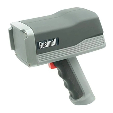
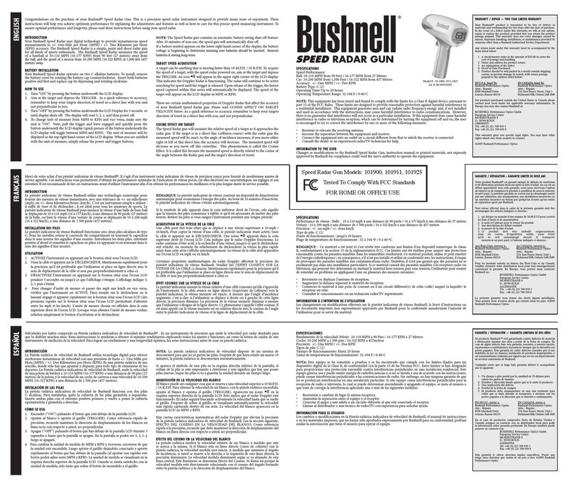
Bushnell Speedster User manual

BUSHNELL SPEEDSTER OPERATORS MANUAL
REGULATORY STATEMENTS
This device complies with Part 15 of the FCC Rules. Operation is subject to the following two conditions:
(1) This device may not cause harmful interference, and (2) this device must accept any interference
received, including interference that may cause undesired operation. Any changes or modifications not
expressly approved by the party responsible for compliance could void the user’s authority to operate the
equipment. This equipment has been tested and found to comply with the limits for a Class B digital device,
pursuant to part 15 of the FCC Rules. These limits are designed to provide reasonable protection against
harmful interference in a residential installation. This equipment generates, uses and can radiate radio
frequency energy and, if not installed and used in accordance with the instructions, may cause harmful
interference to radio communications. However, there is no guarantee that interference will not occur in a
particular installation. If this equipment does cause harmful interference to radio or television reception, which
can be determined by turning the equipment off and on, the user is encouraged to try to correct the interference
by one or more of the following measures:
-Reorient or relocate the receiving antenna.
-Increase the separation between the equipment and receiver.
-Connect the equipment into an outlet on a circuit different from that to which the receiver is
connected.
-Consult the dealer or an experienced radio/TV technician for help.
Your Bushnell® Speedster™ is a precision instrument designed to provide many years of enjoyment. This
booklet will help you achieve optimum performance by explaining its adjustments and features as well as
how to care for this precise speed and statistic measuring instrument. To ensure optimal performance and
longevity, please read these instructions before using your Bushnell Speedster.
INTRODUCTION
Your Bushnell Speedster uses digital technology and DSP (Digital Signal Processing) to provide
instantaneous and accurate speed measurements to +/- One Mile Per Hour (MPH) accuracy. The Bushnell
Speedster is a handy, multi-functional speed gun for all kinds of sports enthusiasts. Track everything from
pitching speeds to cars at the racetrack. The Bushnell Speedster measures the speed of a baseball at 10-
110 MPH from 60 feet away from the ball, and the speed of a racecar from 10-200 MPH at 650 feet away.
Unlike any other speed gun available, the Speedster allows you to keep statistics for baseball and softball,
and provides last and average speeds for any type of object measured.
BATTERY INSTALLATION
Your Bushnell Speedster operates on six AA batteries. To install, remove the battery cover (A) by
depressing both sides of the handle bottom. Remove the battery cartridge (B) and install the batteries so
that the positive (+) and negative (-) terminals of the batteries match the markings inside the battery
cartridge. Re-insert the battery cartridge with batteries in place and then place battery cover back onto the
handle.
GENERAL OPERATION
Your Bushnell Speedster operates on six AA batteries. Make sure they have been installed according to the
instructions listed in the battery installation section.
A QUICK START LESSON
Your Bushnell Speedster can be turned on by pressing the POWER button on the right side of the user
panel below the LCD display (See fig. 1 ). This button will turn on the unit or turn it off at any time during
the operation of the Speedster.
Your Bushnell Speedster can be configured for many different modes of operation. These will be described
in detail in later sections of this manual.

TARGET SPEED AQUISITION
A target can be anything that is moving. To acquire the speed of a target, with the Speedster powered on,
aim the Speedster at the target and depress the trigger. There will be a RADAR ACTIVE icon appear in
the upper right corner of the LCD display. This indicates the Doppler Radar is functioning. The speed of
the target will appear on the LCD display. When the speed appears, release the trigger and the last speed
displayed will “lock” on the display for easy viewing.
There are certain mathematical properties of Doppler Radar that affect the accuracy of your Bushnell
Speedster. Please read COSINE AFFECT ON TARGET VELOCITY later in this manual. As a quick
reference to accuracy, remember to keep your targets direction of travel in a direct line with you.
Fig. 1
USER INPUT SWITCHES AND SCREENS
Definitions for SETUP Screen:
SESSION Resume:Continues average and last speed display and calculations from previous
session
Clear Memory: Clears both average and last speed memory, display and calculations
UNITS MPH: Speed will be displayed in Miles Per Hour
KPH: Speed will be displayed in Kilometers Per Hour
MODE Speed Only: Allows the user to capture speed
Speed + Baseball Stats:Allows the user to record speed and enter Baseball Statistics
To move from one field to the next, or from SESSION to UNITS, SESSION needs to be in bold. Once it
is, press ENTER. Now UNITS will be highlighted. To change from MPH to KPH, press the ↓arrow key
and KPH will appear. To move to MODE, press ENTER and then the ↓arrow key. Once you have
selected session, Units of measure, and Mode, press the PAGE button.

SCREEN DESCRIPTIONS
Screen One – Bushnell Intro Logo (Graphic not same as what is displayed on LCD)
Screen Two – Setup
Edit Fields and Options
1. Session
a. Resume
i) Continue recording and updating stored information
(1) Avg
(2) Last
(3) All Pitcher statistics (Pitches, Balls, Strikes)
b. Clear Memory
i) Clears (erases) all stored Pitchers’ information, Last and Avg statistics
2. Mode
a. Speed Only
i) Unit will record and store limited information, no pitcher statistics stored
(1) Current speed
(2) Last speed
(3) Average (Sum of all recorded speeds ÷Number of recorded speeds)
b. Speed + Baseball Stats
i) Unit will record and store information for up to eight separate pitchers
(1) Current speed
(2) Last speed
(3) Average speed
(4) Total pitch count
(5) Strike count
(6) Ball count
BUSHNELL
SPEEDSTER
SETUP
Session: Resume
Mode: Speed Only
Units: MPH

3. Units
a. MPH
i) All speed information on all screens will be displayed in miles per hour
b. KPH
i) All speed information on all screens will be displayed in kilometers per hour
Screen Three – Speed Only Display
Screen Five – Speed + Baseball Stats Display
Screen Six – Player Edit Screen
SPEED (MPH)
53
LAST 57 AVG 55
Pitcher 1SPEED (MPH) Last 57
Pitches 24 Avg 55
53
Balls Strikes
(↓)30 (↑)12
Player Edit
Pitcher 1
Pitches 24
Balls 30
Strikes 12

USER INPUT SWITCHES
There are six switches on the Speedster, five of which are on the back display panel and one is a “trigger”
position switch. The switches are labeled as:
1. Power On/Off
2. Activate Radar
a. Trigger position switch
b. Dual mode function
i) Activates radar in speed measurement mode
3. Enter
4. Up Arrow
5. Down Arrow
6. Page
General Switch Operation
1. Power On/Off
a. Is always active, regardless of which screen or mode the unit is in
b. Press to turn the unit on and off
c. Is an immediate power off, all DSP and radar activity ceases immediately
i) No speed or statistical information saved in FLASH before powering off
d. Unit will always return to the last MODE (Speed Only OR Speed + Baseball Stats) and UNITS
(MPH OR KPH) setting used each time the device is turned –on.
2. Activate Radar
a. Speed Measurement Mode
i) Press and hold to turn on the transmitter and perform speed processing
(1) Power will be applied to microwave circuitry
(2) AD1881 will be taken from powerdown to speed processing mode of operation
(3) Radar Active Icon will be displayed at top right corner of LCD
ii) Release to turn off the transmitter and to lock display with current speed displayed
(1) Microwave circuitry power will be turned off
(2) AD1881 will be taken from active to powerdown mode of operation
3. Enter – all modes
a. When measuring speeds in Screen Three and/or Screen Five
i) Used to accept current locked display speed into statistical update
ii) Also saves current displayed speed only or player stats information to memory
b. When editing setup in Screen Two
i) Used to accept edit choices during setup/configuration operations
ii) Does NOT update setup information in memory
4. Up Arrow
a. Scroll mode
i) Used to change current parameter edit field up one position in setup screens
b. Edit mode
i) Used to increment/change selected parameter when editing a setup field
c. Stats mode
i) Used to increment BALL count when in baseball stats mode
5. Down Arrow
a. Scroll mode
i) Used to change current parameter edit field down one position in setup screens

b. Edit mode
i) Used to decrement/change selected parameter when editing a setup field
c. Stats mode
i) Used to increment STRIKE count when in baseball stats mode
6. Page
a. Will be used to scroll through selected display, edit and setup screens
i) Actual screen toggle will depend on SPEED ONLY or SPEED + BASEBALL STATS
selected configuration
ii) In SPEED ONLY mode, PAGE will scroll between Screens Two and Three
(1) Screen Two – Setup Display
(2) Screen Three – Speed Only Display
iii) In SPEED + BASEBALL STATS mode, PAGE will scroll through Screens Two, Five and
Six
(1) Screen Two – Setup Display
(2) Screen Five – Speed + Baseball Stats Display
(3) Screen Six – Player Edit Display
b. Will automatically update memory with currently displayed information when in Setup or Player
Edit screens before scrolling to next page
i) Setup – Screen Two
(1) Will update memory with displayed setup choices
(a) Session
(b) Mode
(c) Units
ii) Player Edit – Screen Six
(1) Will update memory with displayed statistics for pitcher shown
(a) Pitcher Number
(b) Pitches
(c) Balls
(d) Strikes
Setup Screen Switch Operation
1. Up Arrow
a. Select operation mode
i) Moves up one field if no field has been selected for editing
ii) Current field will be shown in reverse image text
b. Edit operation choice
i) Increment/changes field if field has been selected for editing
ii) Current operation choice AND operation mode will be shown in reverse image text
2. Down Arrow
a. Select operation mode
i) Moves down one field if no field has been selected for editing
ii) Current field will be shown in reverse image text
b. Edit operation choice
i) Decrement/changes field if field has been selected for editing
ii) Current edit choice AND operation mode will be shown in reverse image text
3. Enter
a. Select operation mode
i) Selects field for editing
b. Edit operation choice

i) Accepts and saves current value displayed in field
ii) Proceeds to the next operation mode for the currently active setup page
4. Page
a. Will have no effect if unit is in edit operation mode
b. Will accept and save all operation choices currently displayed on the setup screen when in select
operation mode
i) Will scroll to the next screen
ii) Next screen displayed determined by operation choices
5. Activate Radar
a. Has no effect while in setup screen
6. Power On/Off
a. Will cancel all current activity of radar
b. Current setup choices will NOT be saved for future operation
c. Unit will be powered down per description in General Switch Operation
Player Edit Screen Switch Operation
1. Up Arrow
a. Select player/count operation
i) Moves up one field if no field has been selected for editing
ii) Current field will be shown in reverse image text
b. Edit player/count
i) Increment count or player display if field has been selected for editing
(1) Maximum Pitcher choice is 8
(2) Maximum count is 999
2. Down Arrow
a. Select player/count operation
i) Moves down one field if no field has been selected for editing
ii) Current field will be shown in reverse image text
b. Edit player/count
i) Decrement count or player display field if field has been selected for editing
(1) Minimum player choice is 1
(2) Minimum count is 0
3. Enter
a. Select player/count operation
i) Selects field for editing
ii) Current operation choice AND operation mode will be shown in reverse image text
b. Edit player/count
i) Accepts and saves current value displayed in field
ii) Proceeds to the next select player/count operation and highlights in reverse image text
4. Page
a. Will have no effect if unit is in edit player/count
b. Will accept and save all edit choices currently displayed on the setup screen when in select
operation mode
i) Will scroll to the next screen
ii) Next screen displayed determined by operation choices
5. Activate Radar /Start-Stop Lap Timer

a. Has no effect while in setup screen
6. Power On/Off
a. Will cancel all current activity of radar
b. Current player edits will NOT be saved for future operation
c. Unit will be powered down per description in General Switch Operation
Cosine Effect on Target Velocity
The Speedster will measure the relative speed of a target as it approaches the Speedster. If the target is in a
direct line (collision course) with the Speedster the measured speed will be exact. As the angle of incidence
increases, if you move either right or left of this direct line, the accuracy will decrease. The measured
speed will decrease as you move off this centerline. This phenomenon is called the Cosine Effect. It is so
called because the measured speed is directly related to the cosine of the angle between the Speedster and
the target’s direction of travel. Figure 1 below relates this to a little league baseball field.
Figure 1

Table 1 below gives calculated distances for the figure 1 above.
Total distance
Pitcher to seats
( ytot)
Distance off center (x)
at a 10° angle
(gives a 1.5% error)
Distance off center (x)
at a 20° angle
(gives a 6% error)
Distance off center (x)
at a 30° angle
(gives a 13% error)
30 5 ft. 10 ft. 17 ft.
40 7 ft. 14 ft. 23 ft.
50 8 ft. 18 ft. 28 ft.
60 10 ft. 21 ft. 34 ft.
70 12 ft. 25 ft. 40 ft.
80 14 ft. 29 ft. 46 ft.
90 15 ft. 32 ft. 51 ft.
100 17 ft. 36 ft. 57 ft.
Table 1
According to the table, assuming the average distance from the pitcher to catcher (y) is 60 feet, there will
also be an average distance behind the catcher to the seats (y1). This is assumed to be an average of 20 feet.
So the total distance from pitcher to Speedster (ytot) is 80 feet for this example. This is the straight-line
direction of ball travel, not the distance from the pitcher to the actual Speedster position, which is R.
If you sit at a distance of 14 ft. off center of the direct pitcher to catcher line, then you have an angle of
incidence of 10°. Most importantly, this gives you an error of 1.5% in measured speed, which is acceptable.
Following the chart across, if you sit 29 ft. off center this correlates to a 20° angle and a 6% error. See the
Measured Speed vs Angle chart for more information on error percentage.
As noted earlier, the larger the angle of incidence the greater the error in the measured speed. Figure 2
below indicates the percent error vs. the angle of incidence.
Figure 2
The graph indicates that at an angle of 0° (direct line) there is no error. If there is an angle of 10° the error
is about 1.5%, for a 20° angle it is about 6% and for a 30° angle the error is about 13%, probably
unacceptable for baseball pitches.
Measured Speed vs Angle (% of actual speed)
0
10
20
30
40
50
60
70
80
90
100
0 10 20 30 40 50 60 70 80 90 100
Angle of Incidence
% of True Speed
Table of contents
Other Bushnell Radar manuals
Popular Radar manuals by other brands

Vaisala
Vaisala IRIS user guide

Furuno
Furuno WR-2100 Operator's manual

Simrad
Simrad R3016 12U/6X Operator's manual

Endress+Hauser
Endress+Hauser Micropilot FMR60B PROFIBUS PA technical information

Endress+Hauser
Endress+Hauser Levelflex FMP56 Brief operating instructions

Carmanah
Carmanah SPEEDCHECK-12 install guide