manuals.online logo
Brands
  1. Home
  2. •
  3. Brands
  4. •
  5. Nexmosphere
  6. •
  7. Controllers
  8. •
  9. Nexmosphere XM-350 User manual

Nexmosphere XM-350 User manual

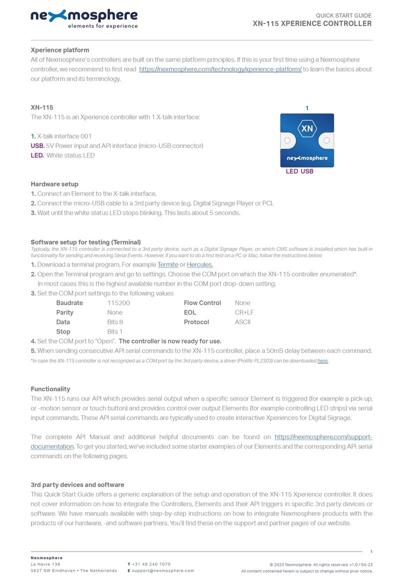
Xperience platform
All of Nexmosphere’s controllers are built on the same platform principles. If this is your rst time using a Nexmosphere
controller, we recommend to rst read https://nexmosphere.com/technology/xperience-platform/ to learn the basics about
our platform and its terminology.
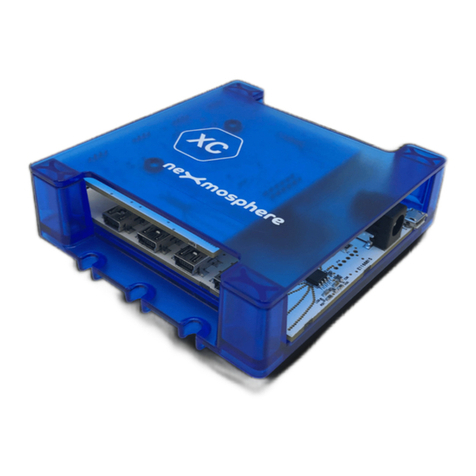
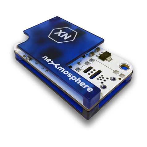
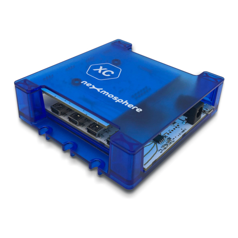
XM-350 with EM-6 expansion
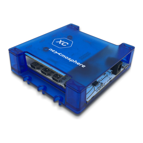
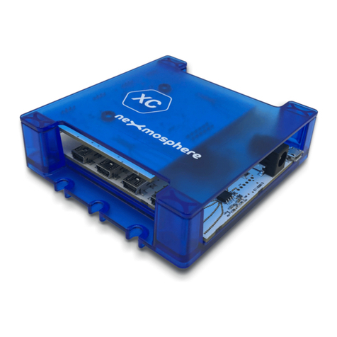
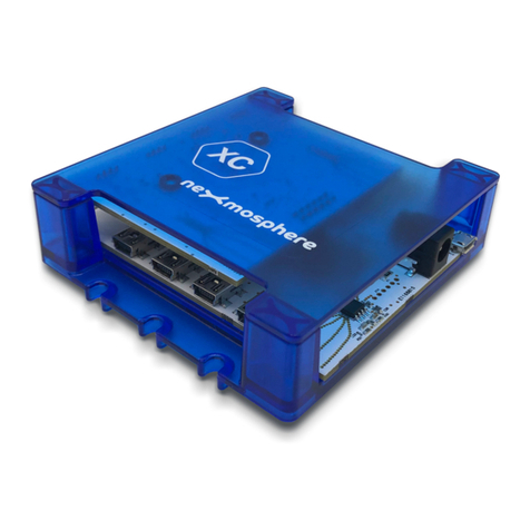
The XM-350 is an Xperience controller with 1 X-talk interface. It can be expanded at our factory with up to 5 EM-6 modules.
An EM-6 module has 5 RGB LED outputs. The API address of an
RGB LED output is the same as the base address of the
module. The specic RGB channel (A, B, C, D or E) can be indicated in the API command itself. For example, if a message is
sent to an RGB channel of the EM-6 module closest to the XM-controller, the API address is 111. The API address of the
X-talk interface on the XM-350 controller is 001.
Hardware setup
1. Connect an Element to the X-talk interface on the XM-350 module.
2. Connect one or more RGB LED strips to any of the RGB LED outputs on the EM-6 module(s).
3. Connect a serial cable* to the API interface and to a 3rd party device (e.g. Mediaplayer or PC).
4. Connect a 12VDC or 24VDC power supply to the DC power socket on the EM-6 module(s).**
Make sure the voltage of the power supply matches the operating voltage of the RGB LED strips.
5. Wait until the green status LED on the XM-350 controller stops blinking. This lasts about 10 seconds.
*Nexmosphere has 2 serial cables available which are compatible with the XM-350: CA-9J9B (RJ9 to 3.5mm jack) and CA-9D9B (RJ9 to DB-9).
Next to these serial cables, a compatible Serial-to-USB cable is also available: CA-9U9B (RJ9 to USB-A). The driver for this cable can be downloaded here.
**No more then 2 power supplies may be connected to an assembled Xperience Controller (XM + EM modules)
Software setup for testing (Terminal)
Typically, the XM-350 controller is connected to a 3rd party device, such as a Digital Signage Player, on which CMS software is installed which has built-in
functionality for sending and receiving Serial Events. However, if you want to do a rst test on a PC or Mac, follow the instructions below:
1. Download a terminal program. For example Termite, Hercules or SerialTools.
2. Open the Terminal program and go to settings. Choose the COM port to which the XM-350 controller is connected*.
3. Set the COM port settings to the following values
Baudrate 115200 Flow Control None
Parity None EOL CR+LF
Data Bits 8 Protocol ASCII
Stop Bits 1
4. Set the COM port to “Open”. The controller is now ready for use.
5. When sending consecutive API serial commands to the XM-350 controller, place a 75mS delay between each command.
*In case the XM-350 controller is connected via a Serial-to-USB cable or adapter, typically this is the highest available number in the COM port drop-down setting.
Nexmosphere
High Tech Campus 10 (Mμ building)
5656 AE Eindhoven • The Netherlands
T +31 40 240 7070
Esupport@nexmosphere.com
QUICK START GUIDE
XM-350 XPERIENCE CONTROLLER WITH EM-6 EXPANSION
© 2020 Nexmosphere. All rights reserved. v1.0 / 07-20
All content contained herein is subject to change without prior notice.
1
111121131141151 00X
B A 1
API
SBDC 5V
SDE D C
B A DC
E D C
B A DC
E D C
B A DC
E D C
B A DC
E D C
LED LED LED LED LED LED
ERR
XM-350EM-6EM-6EM-6EM-6 EM-6
5V. 5VDC Power input (2.5mm DC socket)
DC. 12-24VDC Power input (2.1mm DC)
API. API interface (RJ9 )
SD. SD card slot for bootloading
LED. Green status LED
ERR. Red error LED
Blue
Red
Green
+12/24 V
3rd party devices and software
This Quick Start Guide oers a generic explanation of the setup and operation of the XM-350 controller with EM-6 expansion.
It does not cover information on how to integrate the Controllers, Elements and their API triggers in specic 3rd party devices
or software. We have manuals available with step-by-step instructions on how to integrate Nexmosphere products with the
products of our hardware, -and software partners. You’ll nd these on the support and partner pages of our website.
Functionality
The XM-350 runs our API which provides serial output when a specic sensor Element is triggered (for example a pick-up,
or -motion sensor or touch button) and provides control over output Elements (for example controlling LED strips) via serial
input commands. These API serial commands are typically used to create interactive Xperiences for Digital Signage.
The complete API Manual and additional helpful documents can be found on https://nexmosphere.com/support-
documentation. To get you started, we’ve included some starter examples of our Elements and the corresponding API serial
commands on the following pages.
Nexmosphere
High Tech Campus 10 (Mμ building)
5656 AE Eindhoven • The Netherlands
T +31 40 240 7070
Esupport@nexmosphere.com
QUICK START GUIDE
XM-350 XPERIENCE CONTROLLER WITH EM-6 EXPANSION
© 2020 Nexmosphere. All rights reserved. v1.0 / 07-20
All content contained herein is subject to change without prior notice.
2
Example 1 | RGB LED control
To control an RGB LED strip connected to RGB channel A, B, C, D or E of an EM-6 module, send one of the following API
example commands from the 3rd party device to the XM-350 controller:
Set the LED strip connected to RGB channel A of EM-6 module with address 111 to color 0 (default white*) at 80% brightness
with 0.5 seconds ramp time:
*An overview of the default RGB LED colors is provided on the nal page of this document.
Set the LED strip connected to RGB channel B of EM-6 module with address 111 to color 3 (default blue*) at 100% brightness
with 1.2 seconds ramp time:
Set the LED strip connected to RGB channel C of EM-6 module with address 121 to pulse between two ramps. Ramp1: Color
2 (default green*) at 100% with 1.0 seconds ramp time. Ramp 2: Color 2 (default green*) at 5% with 0.5 seconds ramp time.
Set the LED strip connected to RGB channel D of EM-6 module with address 121 to pulse between two ramps. Ramp1: Color
6 (default turquoise*) at 80% with 0.7 seconds ramp time. Ramp 2: Color 8 (default pink*) at 100% with 0.7 seconds ramp
Set the LED strip of all 5 RGB channels (X) of EM-6 module with address 111 to color 5 (default purple*) at 65% brightness
with 0.8 seconds ramp time:
G111B[A 0 80 5]
G111B[C 3 100 12]
G121B[B 2 100 5 2 5 5]
G121B[E 6 80 7 8 100 7]
G111B[X 5 65 8]
+
B
DC24V
R
G
+
B
R
G
+
B
DC24V
R
G
+
B
R
G
+
B
DC24V
R
G
+
B
R
G
+
B
DC24V
R
G
+
B
R
G
+
B
DC24V
R
G
+
B
R
G
+
B
DC24V
R
G
+
B
R
G
+
B
DC24V
R
G
+
B
R
G
+
B
DC24V
R
G
+
B
R
G
Power supply
(24V)
Power supply
(24V)
CA-9U9B
(connect to
3rd party device)
XM-350
(Xperience
controller)
EM-6
(5x RGB
LED output)
EM-6
(5x RGB
LED output)
B A
E D C
B A
E D C
© 2020 Nexmosphere. All rights reserved. v1.0 / 07-20
All content contained herein is subject to change without prior notice.
Nexmosphere
High Tech Campus 10 (Mμ building)
5656 AE Eindhoven • The Netherlands
T +31 40 240 7070
Esupport@nexmosphere.com
3
QUICK START GUIDE | XM-350 WITH EM-6 EXPANSION
Example 2 | Presence sensor
When an XY-Presence sensor connected to X-talk
interface 001 detects a person in distance zone 4, the
following API serial command is sent from the XM-350 to
the 3rd party device: X001A[4]
When an XY-Presence sensor connected to X-talk
interface 001 does not detect a person, the following API
serial command is sent from the XM-350 to the 3rd party
device: X001A[1]
Example 3 | RFID sensor
When tag 2 is picked up from an antenna connected to
X-talk interface 001, the following API serial commands are
sent from the XM-350 to the 3rd party device:
XR[PU002]
X001A[1]
When tag 1 is placed on an antenna connected to X-talk
interface 001, the following API serial commands are sent
from the XM-350 to the 3rd party device:
XR[PB001]
X001A[0]
Example 4 | Button input
When button 1 of a (touch) button interface connected
to X-talk interface 001 is pressed, the following API serial
commands are sent from the XM-350 to the 3rd party
device: X001A[3]
When button 4 of a (touch) button interface connected
to X-talk interface 001 is pressed, the following API serial
commands are sent from the XM-350 to the 3rd party
device: X001A[17]
XR
XR-C10
(RFID antenna)
XR-C10
RFID Tags
(number 1-3)
XR-DR1
(RFID antenna driver
XM-350
(Xperience
controller)
EM-6
(5x RGB
LED output)
EM-6
(5x RGB
LED output)
CA-9U9B
(connect to
3rd party device)
Power supply
(24V)
XT-B4N6
(4x buon interface)
XT-4F
(Touch buons)
Push buons
(with LED, 4x)
XT-B4
1 2 3 4
XM-350
(Xperience
controller)
EM-6
(5x RGB
LED output)
EM-6
(5x RGB
LED output)
CA-9U9B
(connect to
3rd party device)
Power supply
(24V)
XM-350
(Xperience
controller)
EM-6
(5x RGB
LED output)
EM-6
(5x RGB
LED output)
XY-146
(presence sensor)
CA-9U9B
(connect to
3rd party device)
Power supply
(24V)
© 2020 Nexmosphere. All rights reserved. v1.0 / 07-20
All content contained herein is subject to change without prior notice.
Nexmosphere
High Tech Campus 10 (Mμ building)
5656 AE Eindhoven • The Netherlands
T +31 40 240 7070
Esupport@nexmosphere.com
4
QUICK START GUIDE | XM-350 WITH EM-6 EXPANSION
Example 4 | Button LED control
To set all button LEDs of a (touch) button interface
connected to X-talk interface 001 to “on”, send the
following API commands from the 3rd party device to the
XM-350 controller:
Combining Elements
The XM-350 Xperience controller with EM-6 expansion has up to 25 RGB LED outputs and1 X-talk interface to which any
Element can be connected. To illustrate, Example 1 can be combined with any other example in this Quick Start Guide.
The API commands and operation will remain the same. In case more X-talk interfaces are required, the XM-350 can also
be expanded with EM-8 modules (see XM-350 with EM-8 Quick Start Guide). When connecting multiple Elements that
require a high amount of current (LEDs or push buttons with LED ring), calculate the total required current of the Elements
and check if this is within the specication of the controller and its power supply source.
To set all button LEDs of a (touch) button interface
connected to X-talk interface 001 to “o”, send the
following API commands from the 3rd party device to the
XM-350 controller:
X001A[255]
X001A[0]
XT-B4N6
(4x buon interface)
XT-4F
(Touch buons)
Push buons
(with LED, 4x)
XT-B4
1 2 3 4
XM-350
(Xperience
controller)
EM-6
(5x RGB
LED output)
EM-6
(5x RGB
LED output)
CA-9U9B
(connect to
3rd party device)
Power supply
(24V)
XY-146
(presence sensor)
+
B
DC24V
R
G
+
B
R
G
+
B
DC24V
R
G
+
B
R
G
+
B
DC24V
R
G
+
B
R
G
+
B
DC24V
R
G
+
B
R
G
+
B
DC24V
R
G
+
B
R
G
+
B
DC24V
R
G
+
B
R
G
+
B
DC24V
R
G
+
B
R
G
+
B
DC24V
R
G
+
B
R
G
Power supply
(24V)
CA-9U9B
(connect to
3rd party device)
XM-350
(Xperience
controller)
EM-6
(5x RGB
LED output)
EM-6
(5x RGB
LED output)
B A
E D C
B A
E D C
Power supply
(24V)
Default RGB LED colors
The EM-6 controller is pre-programmed with 10 default colors:
Please refer to the API Manual to learn how to overwrite the default colors with your own preferred RGB LED colors.
R
G
B
0100
100
100
1R
G
B
100
0
0
2R
G
B
0
100
0
3R
G
B
0
0
100
4R
G
B
100
75
0
5R
G
B
100
0
100
6R
G
B
0
100
100
7R
G
B
100
25
0
8R
G
B
100
0
50
9R
G
B
50
100
0

Other Nexmosphere Controllers manuals

Nexmosphere XC-720 User manual

Nexmosphere

Nexmosphere XC-720 User manual

Nexmosphere XC-820 User manual

Nexmosphere

Nexmosphere XC-820 User manual

Nexmosphere XC-841 User manual

Nexmosphere

Nexmosphere XC-841 User manual

Nexmosphere XPERIENCE XC-748 User manual

Nexmosphere

Nexmosphere XPERIENCE XC-748 User manual

Nexmosphere XPERIENCE XN-125 User manual

Nexmosphere

Nexmosphere XPERIENCE XN-125 User manual

Nexmosphere XPERIENCE XM-350 User manual

Nexmosphere

Nexmosphere XPERIENCE XM-350 User manual

Nexmosphere XC-847 User manual

Nexmosphere

Nexmosphere XC-847 User manual

Nexmosphere XM-350 User manual

Nexmosphere

Nexmosphere XM-350 User manual

Nexmosphere XY-240 User manual

Nexmosphere

Nexmosphere XY-240 User manual

Nexmosphere XM-350 User manual

Nexmosphere

Nexmosphere XM-350 User manual

Nexmosphere XM-350 User manual

Nexmosphere

Nexmosphere XM-350 User manual

Nexmosphere SM-125 User manual

Nexmosphere

Nexmosphere SM-125 User manual

Nexmosphere XPERIENCE XC-941 User manual

Nexmosphere

Nexmosphere XPERIENCE XC-941 User manual

Nexmosphere XN-165 XPERIENCE User manual

Nexmosphere

Nexmosphere XN-165 XPERIENCE User manual

Nexmosphere XC-931 User manual

Nexmosphere

Nexmosphere XC-931 User manual

Nexmosphere XN-135 XPERIENCE User manual

Nexmosphere

Nexmosphere XN-135 XPERIENCE User manual

Nexmosphere XC-760 User manual

Nexmosphere

Nexmosphere XC-760 User manual

Nexmosphere Xperience XN-135M8S User manual

Nexmosphere

Nexmosphere Xperience XN-135M8S User manual

Nexmosphere XPERIENCE XN-135M8L User manual

Nexmosphere

Nexmosphere XPERIENCE XN-135M8L User manual

Nexmosphere XN-115 User manual

Nexmosphere

Nexmosphere XN-115 User manual

Nexmosphere XM-350 User manual

Nexmosphere

Nexmosphere XM-350 User manual

Nexmosphere XC-741 User manual

Nexmosphere

Nexmosphere XC-741 User manual

Nexmosphere XN-135M3 User manual

Nexmosphere

Nexmosphere XN-135M3 User manual

Nexmosphere XN-185 User manual

Nexmosphere

Nexmosphere XN-185 User manual

Popular Controllers manuals by other brands

Kelly KLS7270NE user manual

Kelly

Kelly KLS7270NE user manual

Hills Reliance TouchNav User reference guide

Hills Reliance

Hills Reliance TouchNav User reference guide

ENTRYPASS EP.HIO Wiring guide

ENTRYPASS

ENTRYPASS EP.HIO Wiring guide

Mitsubishi Electric L26CPU-BT user manual

Mitsubishi Electric

Mitsubishi Electric L26CPU-BT user manual

Siemens RVP550 installation instructions

Siemens

Siemens RVP550 installation instructions

Salus AKL04P Installation and wiring guide

Salus

Salus AKL04P Installation and wiring guide

Vermes MFC universal user manual

Vermes

Vermes MFC universal user manual

Fisher ED Safety manual

Fisher

Fisher ED Safety manual

Distech Controls DA-020S230DX installation instructions

Distech Controls

Distech Controls DA-020S230DX installation instructions

Danfoss MCD3000 Series manual

Danfoss

Danfoss MCD3000 Series manual

Hanson Electronics DMX18 user manual

Hanson Electronics

Hanson Electronics DMX18 user manual

AirCom R3150 operating manual

AirCom

AirCom R3150 operating manual

Grace m908 user manual

Grace

Grace m908 user manual

ICM Controls ICM870-32A Installation, operation & application guide

ICM Controls

ICM Controls ICM870-32A Installation, operation & application guide

Mitsubishi Electric Central Controller G-50A Operation manual

Mitsubishi Electric

Mitsubishi Electric Central Controller G-50A Operation manual

Parkside PDWE 8 B2 Translation of the original instructions

Parkside

Parkside PDWE 8 B2 Translation of the original instructions

Sentera Controls RTVS8 Series Mounting and operating instructions

Sentera Controls

Sentera Controls RTVS8 Series Mounting and operating instructions

Delta Electronics Programmable Logic Controller DVP-PLC instruction sheet

Delta Electronics

Delta Electronics Programmable Logic Controller DVP-PLC instruction sheet

manuals.online logo
manuals.online logoBrands
  • About & Mission
  • Contact us
  • Privacy Policy
  • Terms and Conditions

Copyright 2025 Manuals.Online. All Rights Reserved.