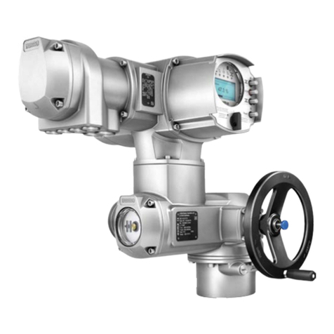
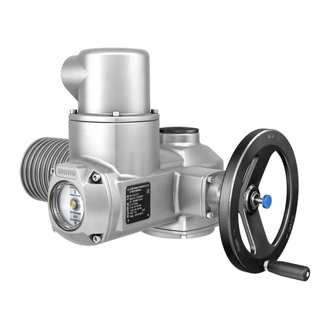
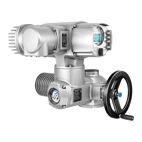
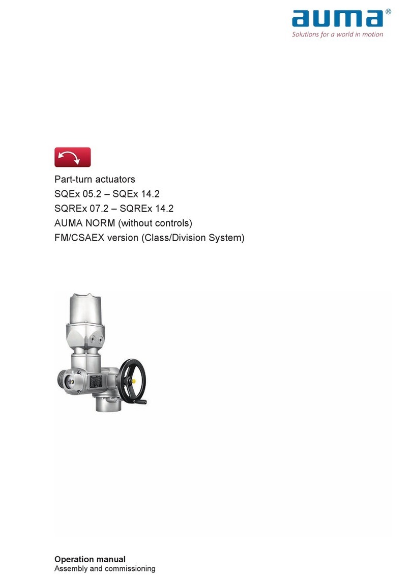
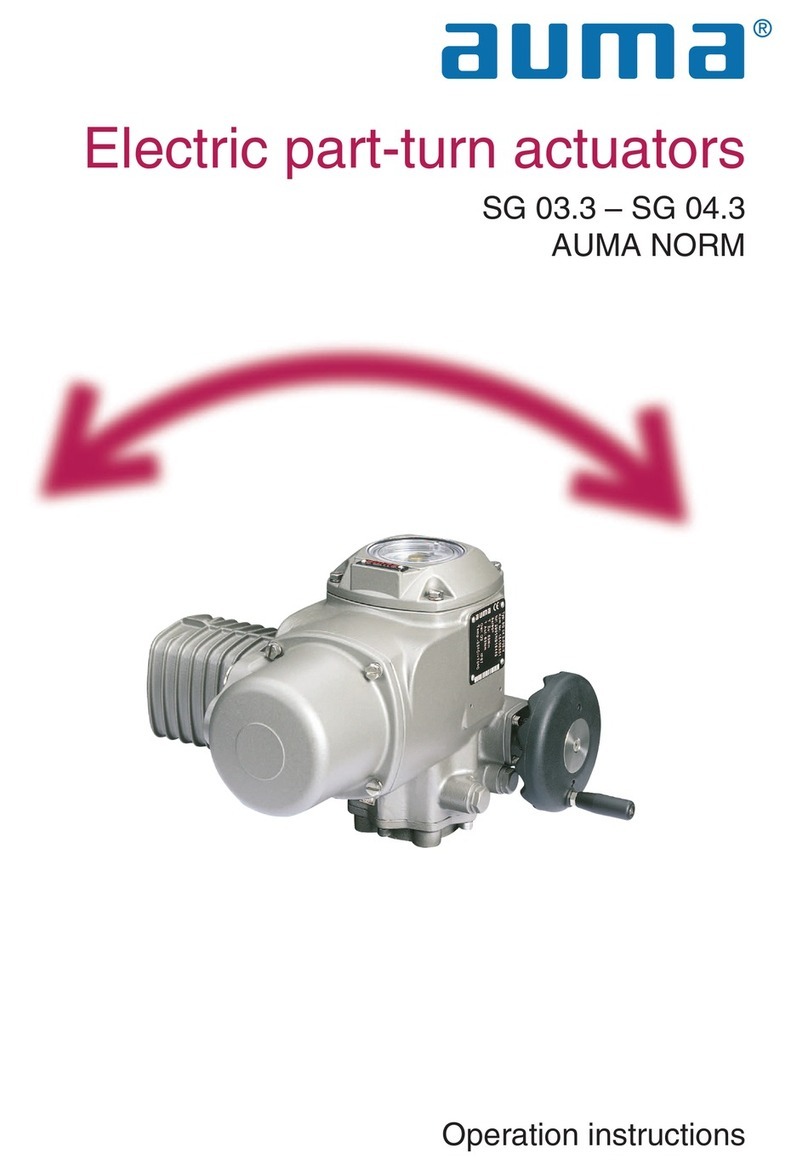
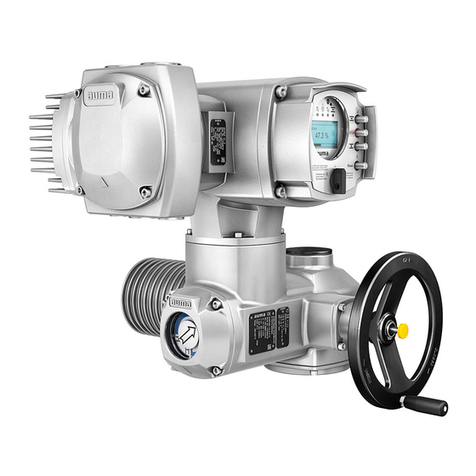
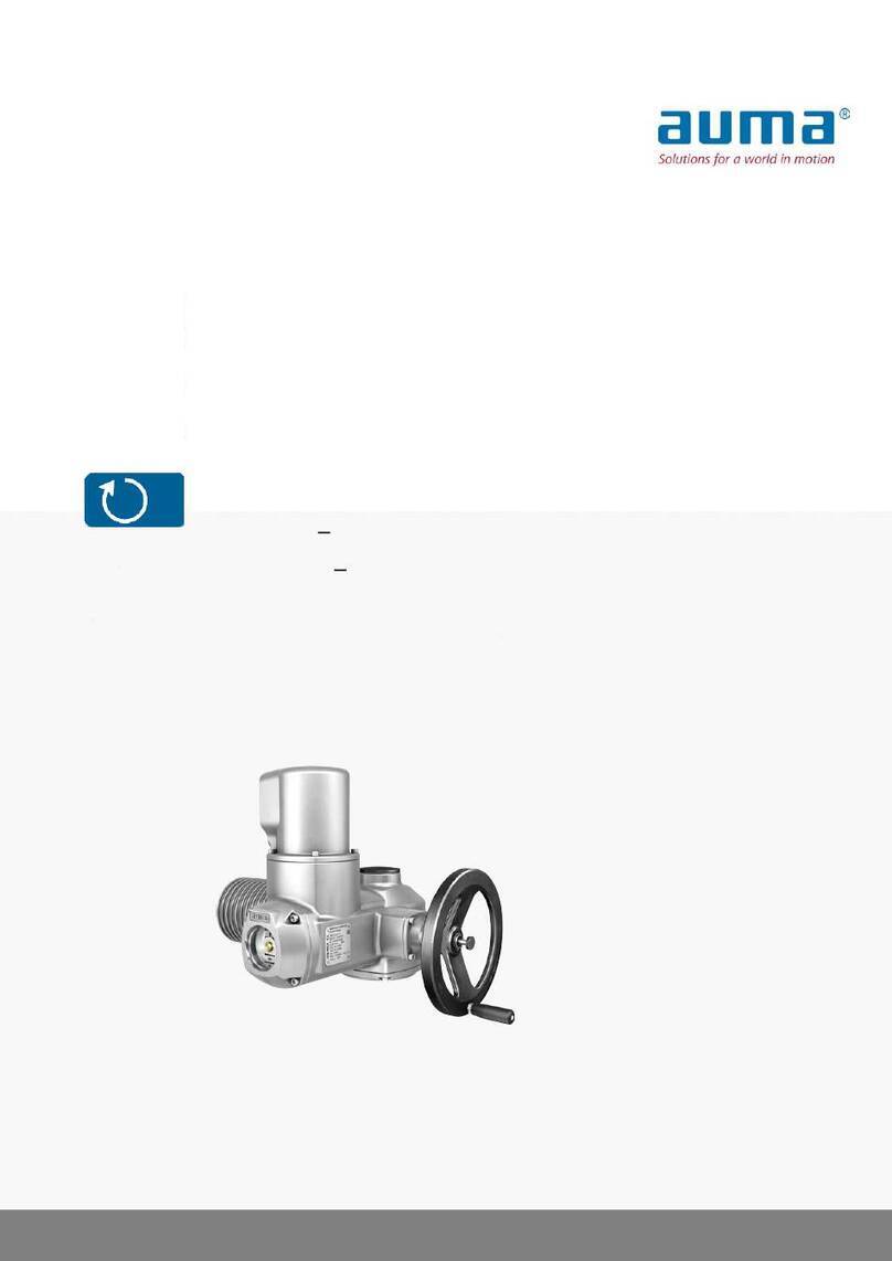
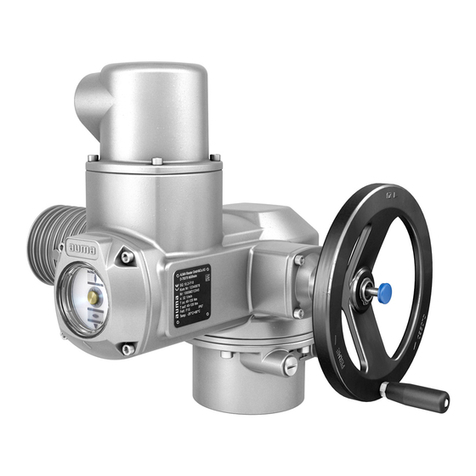
AUMA Aumatic AC 01.1 User manual

Actuator controls
AUMATIC AC 01.1/ACExC 01.1
Profibus DP
Manual Device integration Fieldbus

Table of contents Page
1. Safety instructions . . . . . . . . . . . . . . . . . . . . . . . . . . . . . . . . . . . 4
1.1. General notes regarding safety 4
1.2. Range of application 5
1.3. Warnings and symbols 5
2. General information about Profibus DP . . . . . . . . . . . . . . . . . . . . . . . . 6
2.1. Basic characteristics 6
2.2. Basic functions of Profibus DP 7
2.3. Transfer mode 7
2.4. Bus access 7
2.5. Communication 7
2.6. Functionality 7
2.7. Protection functions 7
2.8. Device types 7
3. Commissioning . . . . . . . . . . . . . . . . . . . . . . . . . . . . . . . . . . . . . 8
3.1. Introduction 8
3.2. Parameter setting 8
3.3. Configuring the Profibus DP interface of the AUMATIC 8
3.4. Communication start-up 9
3.5. AUMA user parameters (AUMA specific parameters) 10
3.5.1 Process representation input (user parameter 1) 10
3.5.2 Settable (user definable) signals (user parameters 2 to 8 and 11 to 34) 10
3.5.3 Alarm contacts/collective fault signal (user parameter 9) 12
3.5.4 Percent/per mil coding for transmission values (user parameter 10) 13
3.6. Profibus DP-V1 services (option) 14
4. Description of the data interface . . . . . . . . . . . . . . . . . . . . . . . . . . . 15
4.1. Input data (process representation input) – signals 15
4.1.1 Process representation input arrangement 1 (default process representation) 15
4.1.2 Process representation input arrangement 2 16
4.1.3 Process representation input arrangement 3 17
4.1.4 Process representation input arrangement 4 18
4.1.5 Signal description within process representation input arrangement 1 (default process representation)
19
4.2. Output data (Process representation output) 28
4.2.1 Description of the output data 28
2
Actuator controls AC 01.1/ACExC 01.1
AUMATIC Manual
Reference documents:
.Operation instructions (Assembly, operation, commissioning) for actuator
.Manual (Operation and setting) AUMATIC AC 01.1/ACExC 01.1 Profibus DP
Can be downloaded from the Internet (www.auma.com) or ordered directly from AUMA
(addresses from page 46).
Read operation instructions first
.Observe safety instructions.
Purpose of the document:
This document is intended to support the system integrator in integrating the fieldbus interface into the DCS.

Page
5. Description of the Profibus DP board. . . . . . . . . . . . . . . . . . . . . . . . . 33
5.1. Displays (optical signals) 33
5.2. Connections: 34
5.2.1 Profibus DP bus connection 34
5.2.2 Customer inputs (option) 34
5.2.3 Redundant bus connection with component redundancy (option) 35
6. Corrective actions . . . . . . . . . . . . . . . . . . . . . . . . . . . . . . . . . . . 36
6.1. Fault indications and warning indications 36
6.2. Diagnostics 36
6.3. Troubleshooting 36
6.3.1 Measuring the Profibus signals using an oscilloscope 39
7. Technical data . . . . . . . . . . . . . . . . . . . . . . . . . . . . . . . . . . . . . 40
8. Appendix – Proposed external wiring diagram. . . . . . . . . . . . . . . . . . . . 41
8.1. Connecting external sensors, 2-wire technology 41
8.2. Connecting external sensors, 3-wire technology 42
8.3. Connecting external sensors, 4-wire technology 43
Index . . . . . . . . . . . . . . . . . . . . . . . . . . . . . . . . . . . . . . . . . .45
Addresses . . . . . . . . . . . . . . . . . . . . . . . . . . . . . . . . . . . . . . . 46
3
Actuator controls AC 01.1/ACExC 01.1
Manual AUMATIC

1. Safety instructions
1.1. General notes regarding safety
4
Actuator controls AC 01.1/ACExC 01.1
AUMATIC Manual
Standards/directives AUMA products are designed and manufactured in compliance with recog-
nised standards and directives. This is certified in a declaration of incorpora-
tion and a declaration of conformity.
The end user or the contractor must ensure that all requirements with
respect to assembly, electrical connection, and commissioning at the place
of installation are met. They include among others:
.Standards and directives such as: EN 60079 “Electrical apparatus for
explosive gas atmospheres"
Part 14: Electrical installations in hazardous areas (other than mines).
Part 17: Inspection and maintenance of electrical installations in hazard-
ous areas (other than mines).
.Applicable configuration directives for fieldbus applications.
Safety instructions/
warnings
All personnel working with this device must be familiar with the safety and
warning instructions in this manual and observe the instructions given.
Safety instructions and warning signs on the device must be observed to
avoid personal injury or property damage.
Qualification of staff Assembly, electrical connection, commissioning, operation, and maintenance
must be carried out exclusively by suitably qualified personnel authorised by the
end user or contractor of the plant.
Prior to working on this product, the staff must have thoroughly read and under-
stood these instructions and, furthermore, know and observe officially recog-
nised rules regarding occupational health and safety.
Work performed in potentially explosive atmospheres is subject to special regu-
lations which have be observed. The end user or contractor of the plant are
responsible for respect and control of these regulations, standards, and laws.
Commissioning Prior to commissioning, it is important to check that all settings are in com-
pliance with the requirements of the application. Incorrect settings might
present a danger to the application, e.g. cause damage to the valve or the
installation.
The manufacturer will not be held liable for any consequential damage. Such
risk lies entirely with the user.
Safe operation Prerequisites for safe and smooth operation:
.Correct transport, proper storage, mounting and installation, as well as
careful commissioning.
.Exclusively operate the device if it is in perfect condition while observing
these instructions.
.Immediately inform about any faults and damage and allow for corrective
measures.
.Observe recognised rules for occupational health and safety.
Protective measures The end user or the contractor are responsible for implementing required
protective measures on site, such as enclosures, barriers, or personal
safety equipment for the staff.
Maintenance Any device modification requires the consent of the manufacturer.

1.2. Range of application
AUMA actuator controls are exclusively designed for the operation of AUMA
actuators.
Other applications require explicit (written) confirmation by the manufac-
turer.
The following applications are not permitted, e.g.:
.motor activation
.pump activation
No liability can be assumed for inappropriate or unintended use.
Observance of these operation instructions is considered as part of the
device’s designated use.
1.3. Warnings and symbols
The following references and symbols are used in these instructions:
Potentially hazardous situation. Failure to observe this warning may result in
property damage.
Information The term Information preceding the text indicates important notes and
information.
For assembly, operation, and commissioning, observe the additional safety
and warning instructions of the reference documents (page 2).
Symbol for CLOSED
Symbol for OPEN
ÆVia the menu to parameter
Describes the path within the menu to the parameter. By using the push but-
tons of the local controls you may quickly find the desired parameter in the
display.
ÈDescription of the parameter settings/indications
Describes the setting/viewing possibilities of a parameter.
òStep by step
Provides a detailed description of each step for setting/viewing the parame-
ter.
5
Actuator controls AC 01.1/ACExC 01.1
Manual AUMATIC
NOTICE

2. General information about Profibus DP
For the exchange of information among automation systems and between
automation systems and the connected distributed field devices, serial
fieldbus systems are mainly used today as the communication system.
Thousands of applications have proved impressively that cost savings of up
to 40 % in wiring, commissioning, and maintenance are achieved by using
fieldbus technology. While in the past the fieldbus systems used were often
manufacturer specific and incompatible with other bus systems, the systems
employed today are almost exclusively open and standardized. This means
that the user does not depend on individual suppliers and can choose the
best product at the most competitive price.
Profibus DP is the leading open fieldbus system in Europe, which is also
used successfully throughout the world. The application range includes
automation in the areas of manufacturing, processing, and building. Profibus
DP is an international, open fieldbus which has been standardized in the
fieldbus standards IEC 61158 and IEC 61784. This standardization ensures
that the investments of manufacturers and users are protected to the best
possible degree and the independence of the manufacturer is guaranteed.
2.1. Basic characteristics
Profibus DP defines the technical and functional features of a serial fieldbus
system allowing the interconnection of distributed, digital automation
devices. Profibus DP distinguishes between master and slave devices.
Profibus DP is designed for fast data transmission on the field level. Here,
central control devices, such as a PLC or PC, communicate via a fast serial
connection with peripheral field stations such as input/output devices,
valves, and actuators.
The interchange of data among these field devices is based on cyclic com-
munication. The necessary communication functions are defined by the
Profibus DP basic functions according to IEC 61158 and IEC 61784.
Master devices control the data traffic on the bus. A master is allowed to
send messages without an external request. Masters are also called ‘active
devices’ in the Profibus protocol.
Slave devices such as AUMA Profibus DP actuators are peripheral devices.
Typical slave devices are input/output devices, valves, actuators, and mea-
suring transmitters. They do not have bus access, i.e. they may only
acknowledge received messages or, at the request of a master, transmit
messages to that master. Slaves are also called ‘passive stations’.
6
Actuator controls AC 01.1/ACExC 01.1
AUMATIC Manual

2.2. Basic functions of Profibus DP
The master reads the input information cyclically from the slaves and writes
the output information cyclically to the slaves. In addition to this
cyclic data transfer of the process representation, Profibus DP also provides
powerful functions for diagnostics and commissioning purposes. The data
traffic is monitored through the monitoring functions on the master and slave
side.
2.3. Transfer mode
.RS-485 twisted pair cable or fibre optic cable.
.AUMA actuators support baud rates up to 1.5 Mbits/s
2.4. Bus access
.Token-passing between the masters and polling between master and
slave.
.Mono-master or multi-master systems are possible.
.Master and slave devices: max. 126 stations connected to one bus
2.5. Communication
.Peer-to-peer (process data exchange [DATA EX]) or Multicast (control
commands to all slaves).
.Cyclic master-slave process data exchange (DATA EX) or acyclic mas-
ter-master data transfer.
2.6. Functionality
.Cyclic process data exchange (DATA EX) between DP master and DP
slaves.
.Dynamic activation or de-activation of individual DP-slaves.
.Checking the configuration of the DP slaves
.Synchronisation of inputs and/or outputs.
2.7. Protection functions
.All messages are transmitted with Hamming Distance HD=4.
.Watchdog timer at DP slaves.
.Access protection for the inputs/outputs of the DP slaves
.Process data exchange (DATA EX) monitoring with configurable timer
interval at the master.
.Adjustable failure behaviour.
2.8. Device types
.DP master class 2 (DPM2), e.g. programming/configuration tools.
.DP master class 1 (DPM1), e.g. central controllers such as PLC, PC.
.DP slave, e.g. AUMA Profibus DP devices. Devices with binary or ana-
logue inputs/outputs, actuators, valves.
7
Actuator controls AC 01.1/ACExC 01.1
Manual AUMATIC

3. Commissioning
3.1. Introduction
When commissioning a Profibus DP network, the stations on the Profibus DP
must be parameterized and configured with the programming software at the
controls (Profibus configurator).
The programming software first reads the GSD file (GeneralStationData) of
the individual actuators. The GSD file contains information about the proper-
ties of the device which is needed by the master. The GSD file can be down-
loaded from our website: www.auma.com.
Information AUMATIC actuator controls up to the logic software version Z031.922/04-00
have a reduced number of parameters. Therefore, a GSD file with reduced
functions is available at www.auma.com (see Readme.txt in
AUMATIC_GSD.zip).
Afterwards, the user can configure and program the device at the Profibus
DP for the programming software of the process control system.
This information is then stored in the controls (DP master) and sent to the
actuators (DP slaves) each time communication is started.
The control is executed via the process representation input and output
bytes.
If a configuration with consistent data is chosen, special functional elements
for the control of the Profibus DP slaves must be used with some PLCs.
3.2. Parameter setting
The parameter setting is partly determined in the Profibus standard, e.g. a
bit for switching bus monitoring on and off (watchdog).
The AUMA Profibus DP control can additionally receive up to 37 bytes of
‘user parameters’, which can be used to set AUMA specific parameters. The
AUMA specific parameters are divided into 34 parameters with 1 byte each
per parameter. The parameters can be changed via the programming soft-
ware of the controls. New programming software supports the setting of the
parameters via text and a menu selection. When using older software, the
values of the parameters must be entered using hexadecimal numbers.
The meaning of the individual AUMA specific parameters is explained in
subclause 3.5.
3.3. Configuring the Profibus DP interface of the AUMATIC
During configuration, the number of input and output bytes reserved for
each device in the controls’ memory is selected. Additionally it is determined
if the data is processed consistently or non-consistently.
Information Only the number of bytes determined in the configuration is transferred
between the DP master and the DP slave.
8
Actuator controls AC 01.1/ACExC 01.1
AUMATIC Manual

9
The following configurations are possible with AUMA Profibus DP actuators:
The number of input bytes states how many of the maximum of 24 bytes the
DP slave sends to the DP master.
The number of output bytes states how many of the maximum of 12 bytes
the DP master sends to the DP slave.
If, for example, the configuration with 8 bytes input is selected, only the first
8 bytes are sent from the DP slave to the DP master. In this case, the mas-
ter does not have access to the bytes 9 to 12.
This way, the DP master saves memory space since it only has to reserve 8
input bytes for the actuator.
The data of the AUMA actuators should be consistently processed by the
DP master. This ensures that the value of a 2-byte variable (position trans-
mitter, analogue customer input) does not change after the reading out the
first byte and, thus, does not distort the value.
If a master does not offer the possibility to use consistent configurations by
means of the process control system, a non-consistent configuration can be
chosen. The values for the position transmitter and the analogue customer
inputs can then be transferred in 1 byte format (Parameter 10 = 0).
3.4. Communication start-up
When the DP master is switched on, it first sends a parameter and configu-
ration telegram to each DP slave. If parameter and configuration are correct,
the DP slave enters the ‘Data Exchange’ mode to exchange process data
between the controls and the slave. Then, the DP master can control the DP
slave and read its current state via the process representation.
If communication is interrupted (e.g. through the switching off of the slave or
the breaking of the Profibus cable), it is resumed automatically by the DP
master when the cause of the fault is eliminated.
Number of input bytes Number of output bytes
11
21
22
44
46
61
62
64
66
84
86
12 4
12 6
16 8
20 8
20 12
22 8
24 8
All these configurations (except 1 In, 1 Out) can be selected as consistent or non-consistent
Table 1

3.5. AUMA user parameters (AUMA specific parameters)
The AUMA specific parameters are set by means of the GSD file.
3.5.1 Process representation input (user parameter 1)
Designation in GSD file:
ExtUserPrmData = 1 “Byte order pattern”
ÈDescription of the parameter settings:
3.5.2 Settable (user definable) signals (user parameters 2 to 8 and 11 to 34)
Within the process representation input, the users can configure the data
contents of 4 signal bytes out of a predefined set of signals themselves.
Designation in GSD file:
.ExtUserPrmData = 2 “Configuration Bit 5.0"
to ExtUserPrmData = 8 ”Configuration Bit 5.6"
(bit 5.7 is intended for collective fault signals, refer to page 12)
.ExtUserPrmData = 11 “Configuration Bit 6.0"
to ExtUserPrmData = 18 ”Configuration Bit 6.7"
.ExtUserPrmData = 19 “Configuration Bit 7.0"
to ExtUserPrmData = 26 ”Configuration Bit 7.7"
.ExtUserPrmData = 27 “Configuration Bit 8.0"
to ExtUserPrmData = 34 ”Configuration Bit 8.7"
ÈDescription of the parameter settings:
10
Actuator controls AC 01.1/ACExC 01.1
AUMATIC Manual
Value in GSD file Text in GSD file Indication in display Description
Prm_Text_Ref = 0 Arrangement 1 0Process representation arrangement 1
(page 15) is used.
Prm_Text_Ref = 1 Arrangement 2 1Process representation arrangement 2
(page 16) is used.
Prm_Text_Ref = 2 Arrangement 3 2Process representation arrangement 3
(page 17) is used.
Prm_Text_Ref = 3 Arrangement 4 3Process representation arrangement 4
(page 18) is used.
Value in GSD file Text in GSD file Indication in display Description
Prm_Text_Ref = 0 Not used NOT USED No signals
Prm_Text_Ref = 1 Closed position CLOSED POSITION Signals LSC (WSR) or LSC (WSR) and TSC
(DSR) (depending on type of seating)
Prm_Text_Ref = 2 Open position OPEN POSITION Signals LSO (WOEL) or LSO (WOEL) and
TSO (DOEL) (depending on type of seating)
Prm_Text_Ref = 3 Running close RUNNING CLOSE Actuator runs logically CLOSE
Prm_Text_Ref = 4 Running open RUNNING OPEN Actuator runs logically OPEN
Prm_Text_Ref = 5 Actuator moving ACTUATOR MOVING
Actuator runs from LOCAL, REMOTE or
manual operation (without positioner only
local or remote operation is indicated).
Prm_Text_Ref = 6 LSC (WSR) LSC (WSR) Limit switch CLOSE operated
Prm_Text_Ref = 7 LSO (WOEL) LSO (WOEL) Limit switch OPEN operated
Prm_Text_Ref = 8 TSC (DSR) TSC (DSR) Torque switch CLOSE operated
Prm_Text_Ref = 9 TSO (DOEL) TSO (DOEL) Torque switch OPEN operated

11
Actuator controls AC 01.1/ACExC 01.1
Manual AUMATIC
Prm_Text_Ref = 10 Thermal fault THERMO FAULT Motor protection has tripped (reset may be
necessary)
Prm_Text_Ref = 11 Torque fault (close) TORQUE FAULT (CLOSE) Torque fault in direction CLOSE occurred
Prm_Text_Ref = 12 Torque fault (open) TORQUE FAULT (OPEN) Torque fault in direction OPEN occurred
Prm_Text_Ref = 13 Torque fault (general) TORQUE FAULT (GEN.) Torque fault CLOSE or OPEN (combined
signal)
Prm_Text_Ref = 14 Setpoint E1 loss SETPOINT E1 LOSS Nominal value signal is by 0.3 mA lower than
the lowest set value
Prm_Text_Ref = 15 Feedback E2 loss FEEDBACK E2 LOSS Actual position signal is by 0.3 mA lower than
the lowest set value
Prm_Text_Ref = 16 Speed E3 loss SPEED E3 LOSS not available
Prm_Text_Ref = 17 Torque E6 loss TORQUE E6 LOSS Torque signal is by 0.3 mA lower than the
lowest set value
Prm_Text_Ref = 18 Warning oper.time
WARNING OPER.TIME
The programmed max. operating time for an
OPEN - CLOSE operation has been
exceeded
Prm_Text_Ref = 19 Warning starts/run WARNING STARTS/RUN The max. number of starts/h or max. running
time/h has been exceeded.
Prm_Text_Ref = 20 Local sw. position LOCAL SW. POSITION Selector switch in position LOCAL
Prm_Text_Ref = 21 Remote sw. position REMOTE SW. POSITION Selector switch in position REMOTE
Prm_Text_Ref = 22 Off sw. position OFF SW. POSITION Selector switch in position OFF
Prm_Text_Ref = 23 Remote mode REMOTE MODE Operation mode REMOTE active
Prm_Text_Ref = 24 Off sw. position SETPOINT MODE Operation mode SETPOINT MODE
Prm_Text_Ref = 25 Intermed. pos.1 INTERMED. POS.1 Signalling the intermediate positions 1 to 4.
Signal behaviour according to POS.1
CONTROL to POS.4 CONTROL
parameters
Prm_Text_Ref = 26 Intermed. pos.2 INTERMED. POS.2
Prm_Text_Ref = 27 Intermed. pos.3 INTERMED. POS.3
Prm_Text_Ref = 28 Intermed. pos.4 INTERMED. POS.4
Prm_Text_Ref = 29 Stepping mode STEPPING MODE Programmed stepping range (START STEP
STOP STEP) parameters) has been entered
Prm_Text_Ref = 30 Closing blink
CLOSING BLINK
Signal is blinking for operation in direction
CLOSE. Signal is active in end position
CLOSED.
Prm_Text_Ref = 31 Opening blink OPENING BLINK Signal is blinking for operation in direction
OPEN. Signal is active in end position OPEN.
Prm_Text_Ref = 32 Fault indication
FAULT IND.
Collective fault signal, includes: internal fault,
torque fault, phase failure, thermal fault and
configuration fault
Prm_Text_Ref = 33 Warning indication
WARNING IND.
Collective fault signal, includes: Operating
time warning, warning starts/run, internal
feedback, internal warnings and loss of signal
Prm_Text_Ref = 34 Not ready indication
NOT READY IND.
Collective fault signal, includes: Clear state,
selector switch not REMOTE, wrong
command, Emergency operation is active,
external operation bus
Prm_Text_Ref = 35 Setpoint reached SETPOINT REACHED Actuator is in nominal position
Prm_Text_Ref = 36 Loss of phase LOSS OF PHASE One phase is missing
Prm_Text_Ref = 37 I/O analogue IN 2 loss I/O ANALOG IN2 LOSS Signal loss of the parallel interface analogue
input 2
Prm_Text_Ref = 38 I/O analogue IN 1 loss I/O ANALOG IN1 LOSS Signal loss of the parallel interface analogue
input 1
Prm_Text_Ref = 39 Selector not remote SELECTOR NOT REMOTE Selector switch not in position REMOTE
Prm_Text_Ref = 40 Wrong command
WRONG COMMAND
Wrong command received (several operation
command bits set or nominal value > 100 %
or > 1000 ‰)
Prm_Text_Ref = 41 Internal fault INTERNAL FAULT An internal fault has occurred, see diagnostic
indication D2
Prm_Text_Ref = 42 PE fault PE FAULT not available
Prm_Text_Ref = 43 Internal feedback
INTERNAL FEEDBACK
Actuator has not yet been opened to full end
position OPEN or closed to full end position
CLOSED
Prm_Text_Ref = 44 Internal warning INTERNAL WARNING An internal warning has occurred, see
diagnostic indication D3
Prm_Text_Ref = 46 Local operation RUNNING LOCAL The actuator is running through an operation
command from the local controls
Prm_Text_Ref = 47 Remote operation RUNNING REMOTE The actuator is running through an operation
command from REMOTE

3.5.3 Alarm contacts/collective fault signal (user parameter 9)
Designation in GSD file:
ExtUserPrmData = 9 “Configuration Fault Bit”
ÈDescription of the parameter settings:
12
Actuator controls AC 01.1/ACExC 01.1
AUMATIC Manual
Prm_Text_Ref = 48 Hand wheel operation RUNNING WITH HANDWHL The actuator is running through turning the
handwheel
Prm_Text_Ref = 49 Proportional operation PROPOTIONAL RUNNING Not available
Prm_Text_Ref = 50 Operation pause PHYS.DRIVE BREAK Actuator is in pause time of stepping mode
Prm_Text_Ref = 51 Clear-state CLEAR-STATUS The Profibus DP interface has received a
Global Control CLEAR telegram
Prm_Text_Ref = 52 Digital input 1 DIG.IN 1 BUS1 A + 24 DC signal is present at the digital input
(1 to 4) of the Profibus interface
Prm_Text_Ref = 53 Digital input 2 DIG.IN 2 BUS1
Prm_Text_Ref = 54 Digital input 3 DIG.IN 3 BUS1
Prm_Text_Ref = 55 Digital input 4 DIG.IN 4 BUS1
Prm_Text_Ref = 56 Intermed. pos.5 INTERMED. POS.5 Signalling of the intermediate positions 5 to 8.
Signal behaviour according to POS.5
CONTROL to POS.8 CONTROL
parameters
Prm_Text_Ref = 57 Intermed. pos.6 INTERMED. POS.6
Prm_Text_Ref = 58 Intermed. pos.7 INTERMED. POS.7
Prm_Text_Ref = 59 Intermed. pos.8 INTERMED. POS.8
Prm_Text_Ref = 60 Emergency stop button EMCY STOP BUTTON The EMERGENCY STOP button (option) has
been operated
Prm_Text_Ref = 61 Fault FO communication FIBER OPTIC LOSS Fault at the fibre optic module (option)
Prm_Text_Ref = 62 Power for brake OK BRAKE SUPPLY FAIL Not available
Prm_Text_Ref = 63 Reset indication RESET INDICATION Not available
Prm_Text_Ref = 64 Digital input 1 DP2 DIG.IN 1 BUS2 Not available
Prm_Text_Ref = 65 Digital input 2 DP2 DIG.IN 2 BUS2
Prm_Text_Ref = 66 Digital input 3 DP2 DIG.IN 3 BUS2
Prm_Text_Ref = 67 Digital input 4 DP2 DIG.IN 4 BUS2
Prm_Text_Ref = 68 Local operation open
RUNNING OPEN (LOCAL)
Actuator is running in direction OPEN (by an
operation command from the local controls or
by turning the handwheel)
Prm_Text_Ref = 69 Local operation close RUNNING CLOSE (LO-
CAL)
Actuator is running in direction CLOSE (by an
operation command from the local controls or
by turning the handwheel)
Prm_Text_Ref = 70 Actuator in intermed.
position INTERMED. POSITION Actuator in intermediate position
Value in GSD file Text in GSD file Indication in display Signals (collective fault signal)
Prm_Text_Ref = 0 Fault group 1 FAULT GROUP 1 Fault ind.
Not ready for operation Remote
Prm_Text_Ref = 1 Fault group 2 FAULT GROUP 2 Fault without torque fault
Not ready for operation Remote
Prm_Text_Ref = 2 Fault group 3 FAULT GROUP 3 Fault ind.
Prm_Text_Ref = 3 Fault group 4 FAULT GROUP 4 Fault without torque fault
Prm_Text_Ref = 4 Fault group 5
FAULT GROUP 5
Fault ind.
Not ready for operation Remote
Warning
Prm_Text_Ref = 5 Fault group 6 FAULT GROUP 6 Fault without thermal fault
Not ready for operation Remote
Prm_Text_Ref = 6 Fault group 7
FAULT GROUP 7
Fault without torque fault + without thermal
fault
Not ready for operation Remote
Prm_Text_Ref = 7 Fault group 8 FAULT GROUP 8 Fault without thermal fault
Prm_Text_Ref = 8 Fault group 9 FAULT GROUP 9 Fault without torque fault + without thermal
fault
Prm_Text_Ref = 9 Fault group 10
FAULT GROUP 10
Fault without thermal fault
Not ready for operation Remote
Warnings

3.5.4 Percent/per mil coding for transmission values (user parameter 10)
This parameter is used to change over the coding of the analogue Profibus
DP transmission values between 0 and 100 %, or 0 and 1,000 ‰.
Designation in GSD file:
ExtUserPrmData = 10 “Format of analogue indications”
ÈDescription of the parameter settings:
13
Actuator controls AC 01.1/ACExC 01.1
Manual AUMATIC
Value in GSD file Text in GSD file Indication in display Description
Prm_Text_Ref = 0 0 to 100 percent 0-100 PERCENT Coding of the analogue values in percent
Prm_Text_Ref = 1 0 to 1000 per mil 0-1000 PER MIL Coding of the analogue values in per mil

3.6. Profibus DP-V1 services (option)
Apart from the cyclic DP-V0 process data exchange, the Profibus DP-V1
services can establish an additional acyclic communication via the fieldbus.
An AUMATIC with activated Profibus DP-V1 service grants access to the
contents of the electronic name plate, the operating data and the most
important operation parameters.
Access to the data of all actuators connected by the Profibus DP network is
therefore enabled, which may be important for preventive maintenance or
uniform parameter setting.
Integration into the process con-
trol system
Different options are available for simple integration of the AUMATIC opera-
tion parameters into the DCS.
For further information refer to
.Device integration with DTM (Device Type Manage) manual
.Device integration with EDD (Electronic Device Description) for Simatic
PDM (Process Device Manager) manual
14
Actuator controls AC 01.1/ACExC 01.1
AUMATIC Manual

4. Description of the data interface
4.1. Input data (process representation input) – signals
Via the process representation input, the master (controls) can read the
state of the slave (actuator).
With AUMA user parameter 1 (page ), a selection can be made from 4 dif-
ferent process representation arrangements.
4.1.1 Process representation input arrangement 1 (default process representation)
Grey bits are collective signals. They contain the results of a disjunction
(OR operation) of other information.
15
Actuator controls AC 01.1/ACExC 01.1
Manual AUMATIC
Bit
7Bit
6Bit
5Bit
4Bit
3Bit
2Bit
1Bit
0
Bit
7Bit
6Bit
5Bit
4Bit
3Bit
2Bit
1Bit
0
Bit
7Bit
6Bit
5Bit
4Bit
3Bit
2Bit
1Bit
0
Bit
7Bit
6Bit
5Bit
4Bit
3Bit
2Bit
1Bit
0
Bit
7Bit
6Bit
5Bit
4Bit
3Bit
2Bit
1Bit
0Bit
7Bit
6Bit
5Bit
4Bit
3Bit
2Bit
1Bit
0
Logical signals Actuator signals
TSC (DSR)
TSO (DOEL)
LSC (WSR)
LSO (WOEL)
Local sw. position
Remote sw. position
Loss of phase
Thermal faut
(Fault 3)
(Not ready ind.)
(Loss of phase)
(Torque fault (OPEN))
(Torque fault (CLOSE))
(Remote sw. position)
(Open position)
(Closed position)
(Runs fom Local)
(Runs from REMOTE)
(Runs via handhweel)
(Actuator moving)
(--)
(Start stepping mode)
Reserved
(Operation pause)
(--)
(--)
(--)
(--)
(--)
(--)
(--)
(--)
Configurable byte 1
DP1 Analogue input
high byte Torque
high byte Torque
low byte
Byte1: Byte 2:
Options part 1
(configurable byte 3)
Byte 7:
Byte 3: E2 (Actual position)
Physical operation
(configurable byte 2)
Byte 6:
Byte 5:
Byte 4: E2 (Actual position)
Options part 2
(configurable byte 4)
Byte 8:
Byte16: Warning signals
part 2
Byte15: Warning signals
part 1
Byte14: Fault signals
Byte13: Not ready ind.
Byte12: E6 (Torque)
Byte 11: E6 (Torque)
Byte 10: DP1 An1
Byte 9: DP1 An1
Actual position high byte
(positioner) Actual position low byte
(positioner)
Fault ind.
Warning ind.
Running CLOSE
Running OPEN
Not ready ind.
Setpoint reached
Closed position
Open position
(DP1 dig. input 4)
(DP1 dig. input 3)
(DP1 dig. input 2)
(DP1 dig. input 1)
(Intermed. pos. 4)
(Intermed. pos. 3)
(Intermed. pos. 2)
(Intermed. pos. 1)
DP1 Analogue input
low byte
Bit
7Bit
6Bit
5Bit
4Bit
3Bit
2Bit
1Bit
0
Bit
7Bit
6Bit
5Bit
4Bit
3Bit
2Bit
1Bit
0
--
Internal fault
Torque fault (CLOSED)
Torque fault (OPEN)
Loss of phase
Thermal fault
--
Config. fault
External operation
Clear state
Emergency mode
Emcy stop active
--
Actuator locked
Selector not remote
Wrong command
Bit
7Bit
6Bit
5Bit
4Bit
3Bit
2Bit
1Bit
0
Bit
7Bit
6Bit
5Bit
4Bit
3Bit
2Bit
1Bit
0
Analog In1 DP1 loss
Analog In2 DP2 loss
--
--
Setpoint E1 loss
Feedback E2 loss
--
Torque E4 loss
Operation time
Starts/run
Internal feedback
Internal warning
I/O1 Anlog In2 loss
I/O1 Anlog In1 loss
--
P-Feedback E4 loss
DP1 Analogue input 2
high byte Reserved for
future extensions Reserved for
future extensions
Byte 20: Reserved
Byte 19: Reserved
Byte 18: DP1 An2
Byte 17: DP1 An2
DP1 Analogue input 2
low byte
Reserved for
future extensions
Byte 22: Reserved
Byte 21: Reserved
Reserved for
future extensions
Byte 24: Reserved
Byte 23: Additional data
Reserved for
future extensions
Bit
7Bit
6Bit
5Bit
4Bit
3Bit
2Bit
1Bit
0
In intermed. position
--
--
–
Intermed. pos. 8
Intermed. pos. 7
Intermed. pos. 6
Intermed. pos. 5

4.1.2 Process representation input arrangement 2
Grey bits are collective signals. They contain the results of a disjunction
(OR operation) of other information.
16
Actuator controls AC 01.1/ACExC 01.1
AUMATIC Manual
Bit
7Bit
6Bit
5Bit
4Bit
3Bit
2Bit
1Bit
0
Bit
7Bit
6Bit
5Bit
4Bit
3Bit
2Bit
1Bit
0
Bit
7Bit
6Bit
5Bit
4Bit
3Bit
2Bit
1Bit
0
Bit
7Bit
6Bit
5Bit
4Bit
3Bit
2Bit
1Bit
0
Bit
7Bit
6Bit
5Bit
4Bit
3Bit
2Bit
1Bit
0Bit
7Bit
6Bit
5Bit
4Bit
3Bit
2Bit
1Bit
0
Logische Meldungen Antriebsmeldungen
DSR
DOEL
WSR
WOEL
Wahlschalter Ort
Wahlschalter Fern
Phasenausfall
Thermofehler
(Störung 3)
(Nicht bereit Fern)
(Phasenausfall)
(DOEL-Fehler)
(DSR-Fehler)
(Wahlschalter Fern)
(Endlage AUF)
(Endlage ZU)
(--)
(--)
(--)
(--)
(--)
(--)
(--)
(--)
DP1 Analoger Eingang
High-Byte
Drehmoment
High-Byte Drehmoment
Low-Byte
Byte1: Byte 2: Byte 3: E2 (Istposition) Byte 4: E2 (Istposition)
Byte16: Warnungsmeldungen
Teil 2
Byte15: Warnungsmeldungen
Teil 1
Byte14: Fehlermeldungen
Byte13: Nicht bereit Fern
Byte12: E6 (Drehmoment)
Byte 11: E6 (Drehmoment)
Byte 10: DP1 An1
Byte 9: DP1 An1
Istposition High-Byte
(Stellungsgeber) Istposition Low-Byte
(Stellungsgeber)
Fehlermeldungen
Warnungsmeldungen
Faehrt ZU
Faehrt AUF
Nicht bereit Fern
Ist Soll
Endlage ZU
Endlage AUF
DP1 Analoger Eingang
Low-Byte
Bit
7Bit
6Bit
5Bit
4Bit
3Bit
2Bit
1Bit
0
Bit
7Bit
6Bit
5Bit
4Bit
3Bit
2Bit
1Bit
0
--
Interne Fehler
DSR Fehler
DOEL Fehler
Phasenausfall
Thermo Fehler
--
Konfigurationsfehler
Bit
7Bit
6Bit
5Bit
4Bit
3Bit
2Bit
1Bit
0
Bit
7Bit
6Bit
5Bit
4Bit
3Bit
2Bit
1Bit
0
DP1 Analoger Eingang 2
High-Byte
Byte 18: DP1 An2
Byte 17: DP1 An2
DP1 Analoger Eingang 2
Low-Byte
Konfigurierbares Byte 1
Byte 6: Physikalische Fahrt
(Konfigurierbares Byte 2)
Byte 5:
Byte 7: Optionen Teil 1
(Konfigurierbares Byte 3)
(DP1 dig. Eingang 4)
(DP1 dig. Eingang 3)
(DP1 dig. Eingang 2)
(DP1 dig. Eingang 1)
(Zwischenstellung 4)
(Zwischenstellung 3)
(Zwischenstellung 2)
(Zwischenstellung 1)
(Faehrt von Ort)
(Faehrt von Fern)
(Faehrt mit Handrad)
(Antrieb fährt)
--
(Taktstrecke betreten)
(Proportionalfahrt)
(Fahrpause)
Externer Betrieb
Clear Zustand
NOT-Fahrt aktiv
NOT-AUS aktiv
--
Antrieb verriegelt
Wahlschalter n. FERN
Falsches Kommando
SigBr. DP1 An In1
SigBr. DP1 An IN2
--
--
SigBr. Sollpos. E1
SigBr. Sollpos. E2
SigBr. LWL-Modul
SigBr. Drehmoment E6
Stellzeitwarnung
ED-Warnung
keine Referenzfahrt
Interne Warnung
SigBr. PAR1 An In2
SigBr. PAR1 An In1
--
SigBr. Prozessistwert E4
Für zukünftige Erweiterungen
reserviert Für zukünftige Erweiterungen
reserviert
Byte 20: Reserviert
Byte 19: Reserviert
Für zukünftige Erweiterungen
reserviert
Byte 22: Reserviert
Byte 21: Reserviert
Für zukünftige Erweiterungen
reserviert
Byte 24: Reserviert
Byte 23: Zusatzdaten
Für zukünftige Erweiterungen
reserviert
Bit
7Bit
6Bit
5Bit
4Bit
3Bit
2Bit
1Bit
0
In Zwischenstellung
--
--
--
Zwischenstellung 8
Zwischenstellung 7
Zwischenstellung 6
Zwischenstellung 5
Byte 8: Optionen Teil 2
(Konfigurierbares Byte 4)

4.1.3 Process representation input arrangement 3
Grey bits are collective signals. They contain the results of a disjunction
(OR operation) of other information.
17
Actuator controls AC 01.1/ACExC 01.1
Manual AUMATIC
Bit
7Bit
6Bit
5Bit
4Bit
3Bit
2Bit
1Bit
0
Bit
7Bit
6Bit
5Bit
4Bit
3Bit
2Bit
1Bit
0
Bit
7Bit
6Bit
5Bit
4Bit
3Bit
2Bit
1Bit
0
Bit
7Bit
6Bit
5Bit
4Bit
3Bit
2Bit
1Bit
0
Bit
7Bit
6Bit
5Bit
4Bit
3Bit
2Bit
1Bit
0Bit
7Bit
6Bit
5Bit
4Bit
3Bit
2Bit
1Bit
0
Logical signals Actuator signals
TSC (DSR)
TSO (DOEL)
LSC (WSR)
LSO (WOEL)
Local sw. position
Remote sw. position
Loss of phase
Thermal faut
(Fault 3)
(Not ready ind.)
(Loss of phase)
(Torque fault (OPEN))
(Torque fault (CLOSE))
(Remote sw. position)
(Open position)
(Closed position)
(Runs fom Local)
(Runs from REMOTE)
(Runs via handhweel)
(Actuator runs)
(--)
(Start stepping mode)
(Proportional operation)
(Operation pause)
(--)
(--)
(--)
(--)
(--)
(--)
(--)
(--)
Configurable byte 1 Physical operation
(configurable byte 2)
DP1 Analogue input
high byte
Torque
high byte Torque
low byte
Byte1: Byte 2:
Options part 1
(configured byte 3)
Byte 7:
Byte 3: E2 (Actual position)
Byte 6:
Byte 5: Byte 4: E2 (Actual position)
Options part 2
(configured byte 4)
Byte 8:
Byte16: Warning signals
part 2
Byte15: Warning signals
part 1
Byte12: E6 (Torque)
Byte 11: E6 (Torque)
Byte 10: DP1 An1
Byte 9: DP1 An1
Actual position high-byte
(positioner) Actual position low-byte
(positioner)
Fault ind.
Warning ind.
Running CLOSE
Running OPEN
Not ready ind.
Setpoint reached
Closed position
Open position
(DP1 dig. input 4)
(DP1 dig. input 3)
(DP1 dig. input 2)
(DP1 dig. input 1)
(Intermed. pos. 4)
(Intermed. pos. 3)
(Intermed. pos. 2)
(Intermed. pos. 1)
DP1 Analogue input
low byte
Bit
7Bit
6Bit
5Bit
4Bit
3Bit
2Bit
1Bit
0
Bit
7Bit
6Bit
5Bit
4Bit
3Bit
2Bit
1Bit
0
Analog In1 DP1 loss
Analog In2 DP2 loss
--
--
Setpoint E1 loss
Feedback. E2 loss
Fiber optic loss
Torque E4 loss
Operation time
Starts/run
Internal feedback
Internal warning
I/O1 Anlog In2 loss
I/O1 Anlog In1 loss
--
P-Feedback E4 loss
DP1 Analogue input 2
high byte
Byte 18: DP1 An2
Byte 17: DP1 An2
DP1 Analogue input 2
low byte
Reserved for
future extensions
Byte 22: Reserved
Byte 21: Reserved
Reserved for
future extensions
Byte14: Fault signals
Byte13: Not ready ind.
Bit
7Bit
6Bit
5Bit
4Bit
3Bit
2Bit
1Bit
0
--
Internal fault
Torque fault (CLOSE)
Torque fault (OPEN)
Loss of phase
Thermal fault
--
Config. fault
Bit
7Bit
6Bit
5Bit
4Bit
3Bit
2Bit
1Bit
0
External operation
Clear state
Emergency mode
Emcy stop active
--
Actuator locked
Selector not remote
Wrong command
Reserved for
future extensions Reserved for
future extensions
Byte 20: Reserved
Byte 19: Reserved
Byte 24: Reserved
Byte 23: Additional data
Reserved for
future extensions
Bit
7Bit
6Bit
5Bit
4Bit
3Bit
2Bit
1Bit
0
In intermed. position
--
--
--
Intermed. pos. 8
Intermed. pos. 7
Intermed. pos. 6
Intermed. Pos. 5

4.1.4 Process representation input arrangement 4
Grey bits are collective signals. They contain the results of a disjunction
(OR operation) of other information.
18
Actuator controls AC 01.1/ACExC 01.1
AUMATIC Manual
Bit
7Bit
6Bit
5Bit
4Bit
3Bit
2Bit
1Bit
0
Bit
7Bit
6Bit
5Bit
4Bit
3Bit
2Bit
1Bit
0
Bit
7Bit
6Bit
5Bit
4Bit
3Bit
2Bit
1Bit
0
Bit
7Bit
6Bit
5Bit
4Bit
3Bit
2Bit
1Bit
0
Bit
7Bit
6Bit
5Bit
4Bit
3Bit
2Bit
1Bit
0Bit
7Bit
6Bit
5Bit
4Bit
3Bit
2Bit
1Bit
0
Logical signals Actuator signals
TSC (DSR)
TSO (DOEL)
LSC (WSR)
LSO (WOEL)
Local sw. position
Remote sw. position
Loss of phase
Thermal faut
(Fault 3)
(Not ready ind.)
(Loss of phase)
(Torque fault (OPEN))
(Torque fault (CLOSE))
(Remote sw. position)
(Open position)
(Closed position)
(Runs fom Local)
(Runs from REMOTE)
(Runs via handhweel)
(Actuator moving)
(--)
(Start stepping mode)
(Proportional operation)
(Operation pause)
(--)
(--)
(--)
(--)
(--)
(--)
(--)
(--)
Configured byte 1
Torque
high byte Torque
low byte
Byte1: Byte 2:
Options part 1
(configured byte 3)
Byte 7:
Byte 3: E2 (Actual position)
Physical operation
(configured byte 2)
Byte 6:
Byte 5: Byte 4: E2 (Actual position)
Options part 2
(configured byte 4)
Byte 8:
Byte12: E6 (Torque)
Byte 11: E6 (Torque)
Actual position high-byte
(positioner) Actual position low-byte
(positioner)
Fault ind.
Warning ind.
Running CLOSE
Running OPEN
Not ready ind.
Setpoint reached
Closed position
Open position
(DP1 dig. input 4)
(DP1 dig. input 3)
(DP1 dig. input 2)
(DP1 dig. input 1)
(Intermed. pos. 4)
(Intermed. pos. 3)
(Intermed. pos. 2)
(Intermed. pos. 1)
DP1 Analogue input 1
high byte
Byte 18: DP1 An1
Byte 9: DP1 An1
DP1 Analogue input 1
low byte
Byte16: Warning signals
part 2
Byte15: Warning signals
part 1
Byte14: Fault signals
Byte13: Not ready ind.
Bit
7Bit
6Bit
5Bit
4Bit
3Bit
2Bit
1Bit
0
--
Internal fault
Torque fault (CLOSE)
Torque fault (OPEN)
Loss of phase
Thermal fault
--
Config. fault
Bit
7Bit
6Bit
5Bit
4Bit
3Bit
2Bit
1Bit
0
Bit
7Bit
6Bit
5Bit
4Bit
3Bit
2Bit
1Bit
0
Analog In1 DP1 loss
Analog In2 DP2 loss
--
--
Setpoint E1 loss
Feedback. E2 loss
Fiber Optic loss
Torque E6 loss
Operation time
Starts/run
Internal feedback
Internal warning
I/O1 Analog In2 Loss
I/O1 Analog In1 Loss-
Channel 2 active
P-Feedback E4 loss
DP1 Analogue input 2
high byte
Byte 18: DP1 An2
Byte 17: DP1 An2
DP1 Analogue input 2
low byte
Reserved for
future extensions
Byte 22: Reserved
Byte 21: Reserved
Reserved for
future extensions
Bit
7Bit
6Bit
5Bit
4Bit
3Bit
2Bit
1Bit
0
External operation
Clear state
Emergency mode
Emcy stop active
--
Actuator locked
Selector not remote
Wrong command
Reserved for
future extensions Reserved for
future extensions
Byte 20: Reserved
Byte 19: Reserved
Byte 24: Reserved
Byte 23: Additional data
Reserved for
future extensions
Bit
7Bit
6Bit
5Bit
4Bit
3Bit
2Bit
1Bit
0
Intermed. position
--
--
--
Intermed. pos. 8
Intermed. pos. 7
Intermed. pos. 6
Intermed. Pos. 5

4.1.5 Signal description within process representation input arrangement 1 (default process representa-
tion)
Byte 1: Logical signals
Bits 3, 6, and 7 are collective signals.
Bits 5 and 4 of the logical signals
(byte1) indicate a logical operation of
the actuator, i.e.they are set when the
actuator has received the command
to perform an electrical operation
(also present when e.g. the actuator
happens to be in a stepping pause
during stepping mode or waits for the
end of the dead time)
19
Actuator controls AC 01.1/ACExC 01.1
Manual AUMATIC
Bit Designation Value Short description
0
Open position
For limit seating in
end position OPEN
1Limit switch operated in direction OPEN
0No signals
Open position
For torque seating in
end position OPEN
1Torque switch and limit switch operated
in direction OPEN
0No signals
1
Closed position
For limit seating in
end position CLOSED
1Limit switch operated in direction CLOSE
0No signals
Closed position
For torque seating in
end position CLOSED
1Torque switch and limit switch operated
in direction CLOSE
0No signals
2Setpoint reached 1
The setpoint is within max. error variable
(outer dead band). Signal occurs only if
Profibus DP master has set the Remote
SETPOINT bit.
0No signals
3Not ready ind.
1
Collective signal: contains the result of a
disjunction (OR-operation) of all bits com-
prised in the “Not ready ind.” byte
(page 23).
0No signal is active in “Not ready ind.”
byte (page 23).
4Running OPEN 1
Operation command (OPEN or
SETPOINT) from Profibus DP in direction
OPEN is executed. For operation in step-
ping mode, this signal is also active dur-
ing an off-time, the dead time, and the re-
versing prevention.
0No operation is carried out via Profibus
DP
5Running CLOSE 1
Operation command (CLOSE or
SETPOINT) from Profibus DP in direction
CLOSE is executed. For operation in
stepping mode, this signal is also active
during an off-time, the dead time, and the
reversing prevention.
0No operation is carried out via Profibus
DP
6Warning ind.
1Collective signal: contains a disjunction
(OR-operation) of all bits comprised in
the “Warning ind.” byte (page 25).
0No warnings are active (all bits of the
warnings cancelled)
7Fault ind.
1Collective signal: contains the result of a
disjunction (OR-operation) of all bits com-
prised in the “Fault ind.” byte (page 24)
0No faults are active (all bits are cancelled
in the fault byte)
Table 2

Byte 2: Actuator signals
Bytes 3 and 4:
E2 (actual position) high byte
Byte 3 = high byte, byte 4 = low byte.
If a position transmitter (potentiometer, RWG, or MWG) is installed in the
actuator, bytes 3 and 4 are used to transmit the current actuator position.
The value can be transmitted either in percent (value: 0 – 100) or in per mil
(value 0 – 1000). The coding (percent or per mil) is selected via the AUMA
user parameter 10: “Format of analogue indication” (page 13).
For the scale 0 – 100, only the low byte requires evaluation.
Byte 5: Configurable byte 1
The bits in the configurablebyte 5 can
be assigned to different signals. Bit 7
is only for fault signals, the other bits
for other signals. The bit assignment
is defined via parameters in the GSD
file (default assignments are indi-
cated in the table).
20
Actuator controls AC 01.1/ACExC 01.1
AUMATIC Manual
Bit Designation Value Short description
0Thermal
fault
1A thermal fault (motor protection) has oc-
curred.
0No thermal fault has occurred.
1Loss of phase 1One phase is missing.
0All phases are present.
2Remote sw position
1Selector switch is in position REMOTE.
0Selector switch is not in position RE-
MOTE.
3Local sw. position 1Selector switch is in position LOCAL.
0Selector switch is not in position LOCAL.
4LSO (WOEL) 1Limit switch OPEN left operated.
0Limit switch OPEN left not operated.
5LSC (WSR) 1Limit switch CLOSE right operated.
0Limit switch CLOSE right not operated.
6TSO (DOEL) 1Torque switch OPEN left operated (stor-
ing).
0Torque switch OPEN left not operated.
7TSC (DSR) 1Torque switch CLOSE right operated
(storing).
0Torque switch CLOSE right not operated.
Table 3
Bit Designation Value Short description
0
Closed position
Limit seating in end
position CLOSED
1Limit switch operated in direction
CLOSE.
0No signals
Closed position
Torque seating in end
position CLOSED
1Torque switch and limit switch operated
in direction CLOSE.
0No signals
1
Open position
Limit seating in end
position OPEN
1Limit switch operated in OPEN direction.
0No signals
Open position
Torque seating in end
position OPEN
1Torque switch and limit switch operated
in direction OPEN.
0No signals
2Remote sw. position 1Selector switch is in position REMOTE
0No signals
3Torque fault
(CLOSE)
1Torque fault in CLOSE direction (storing)
0No signals
4Torque fault (OPEN) 1Torque fault in OPEN direction (storing)
0No signals
Table 4
Other manuals for Aumatic AC 01.1
4
This manual suits for next models
1
Table of contents
Other AUMA Controllers manuals

AUMA
AUMA PROFOX PF-M25 Manual

AUMA
AUMA SA 07.2 User manual
AUMA
AUMA PF-M25 Series Manual
AUMA
AUMA SA 16.2 User manual
AUMA
AUMA SA Series User manual
AUMA
AUMA SAEx 07.2 User manual

AUMA
AUMA SQ 05.2-SQ 14.2 User manual
AUMA
AUMA SGExC 05.1 User manual
AUMA
AUMA SQVEx 05.2 User manual
AUMA
AUMA AUMATIC AC 01.2 User manual
Popular Controllers manuals by other brands
Avlite
Avlite AV-OL-CTRL-T3 Installation & service manual
UCS
UCS QUASAR AC user manual
SOLOMON SYSTECH
SOLOMON SYSTECH SSD1331 Technical data
Mitsubishi Electric
Mitsubishi Electric Melservo-J5 MR-J5 Series user manual
Johnson Controls
Johnson Controls M9220-GGx-3 series installation instructions
Auber
Auber SYL-23X2P Quick List
