BUTZBACH SPACELITE HT40 User manual

Operating manual
Butzbach System Anti-drop
device

Butzbach GmbH Industrietore Originalbedienungsanleitung Absturzsicherung_V1 24/02/2021 I
Masthead
Copyright by Butzbach GmbH Industrietore, Weiherstraße 16, D-89293 Kellmünz
All rights reserved. This manual may not be reproduced or disseminated in any manner without the prior
consent of Butzbach GmbH Industrietore.
Butzbach GmbH Industrietore reserves the right to make changes to illustrations and information in this
operating manual in order to incorporate technical advances. This operating manual was created with great
care and is revised regularly. However, despite all checks it cannot be ruled out that technical inaccuracies
and typographical errors were missed. All errors known to us will be removed in new editions, for which reason
we are grateful at all times for information about errors in this operating manual.
If this operating manual is not heeded, all warranty claims shall be void!
The operating manual should be kept near the door system for future use!
The "Operating Manual Butzbach System Anti-drop device" applies in addition to the “SPACELITE®
or SECTIOLITE® Operating Manual". A requirement for the use of this manual is that the "SPACELITE®
or SECTIOLITE®Operating Manual" has been read and understood. The content of the "SPACELITE®
or SECTIOLITE®Operating Manual" applies to its full extent for the "Operating Manual Butzbach System
Anti-drop device". Additional information is contained in the "Operating Manual Butzbach System Anti-drop
device".
This operating manual applies to the following types of Butzbach anti-drop device systems:
AS HT40 / TW PG
AS HT60/80
AS HT80
AS HT150

Butzbach GmbH Industrietore Originalbedienungsanleitung Absturzsicherung_V1 24/02/2021 II
Contents
Masthead.............................................................................................................................................................I
1Functioning of the anti-drop device system ................................................................................................1
1.1 Design.................................................................................................................................................1
1.2 Function..............................................................................................................................................1
1.3 Automatic shut-off device...................................................................................................................1
2Areas of use of the anti-drop device system...............................................................................................1
3Testing the anti-drop device system ...........................................................................................................2
4Maintenance of the anti-drop device system ..............................................................................................3
4.1Inspection of the guide rails................................................................................................................3
4.2 Dismantling the fall arrestors..............................................................................................................3
4.3 Inspection and maintenance of the fall arrestors................................................................................3
4.4 Reinstallation of the fall arrestors.......................................................................................................3
4.5 Inspection of the locking function .......................................................................................................3
4.6 Connection and inspection of the automatic shut-off device..............................................................4
5Technical Data ............................................................................................................................................5
Index...................................................................................................................................................................6

Functioning of the anti-drop device system
Butzbach GmbH Industrietore Originalbedienungsanleitung Absturzsicherung_V1 24/02/2021 1
1 Functioning of the anti-drop device system
1.1 Design
The anti-drop device system consists of two fall arrestors with locking devices, which are in the lateral guide
rails of the stacking door. The fall arrestors are attached to the bottom gate panel. Support rails and control
rails are pressed into the guide rails, which allow the fall arrestors to operate. An automatic shut-off is located
on the bottom door panel. After the locking devices engages, the door operation is switched off.
Only for a movable partition: The door motor switches off by engaging overload protection.
1.2 Function
The anti-drop device works as a function of speed. If a certain door closing speed is exceeded, the locking
devices latch into place in the support rails and block the bottom gate panel. The braking and stopping forces
that are thereby released are routed to the building structure through the guide rails and their connecting
pieces.
A spring on a pendulum (pendulum lock) prevents the pendulum being disengaged from the support rail due
to subsequent vibrations of the door panel, and thus prevents the door from continuing to fall.
1.3 Automatic shut-off device
The automatic shut-off device is mounted to both sides of the bottom door panel and each is equipped with
a limit switch with a forced opening contact. When the locking devices engage, the bottom door panel stops,
the next door panel runs up to the limit switch and operates it. The door motor switches off.
2 Areas of use of the anti-drop device system
The anti-drop device systems are employed in the following door types from Butzbach GmbH Industrietore.
Type
Use in door types
AS HT40 / TW PG
SPACELITE®HT40; Wall partition TW PG
AS HT60/80
SPACELITE®HT60N, HT60H, HT80/ 260
AS HT80
SPACELITE®HT80/ 400
AS HT150
SPACELITE®HT150; Hydraulic: HTH150, HT180
Warning! Restoration of operational readiness after each triggering
event!
Each time that it is triggered, e.g. after a fall, the operational readiness of the anti-drop device system must
be restored by means of servicing.

Testing the anti-drop device system
Butzbach GmbH Industrietore Originalbedienungsanleitung Absturzsicherung_V1 24/02/2021 2
3 Testing the anti-drop device system
According to the Regulations of the Main Association of the Industrial Trade Associations, the anti-drop device
system, as part of the door, is to be tested by a qualified professional before first being put into services and
at least once annually pursuant to the Technical Regulations for Doors and Gates in Workplaces ASR A1.7
(previously BGR 232).
Situation
Possible characteristics
If, while checking the
general condition of the
door, it is determined
that
- the door system is extraordinarily severely dirty or was not sufficiently maintained.
- the door construction shows damage, e.g. damaged door elements or guide rails
- the maintenance intervals are exceeded
- the expected useful life has been reached (age of the door system, number of times
door opened).
If, while checking the
conditions of use, it is
determined that
- an unusually large quantity of dust has entered into the door's mechanical parts,
- the door system is exposed to corrosive gases or liquids, e.g. in areas of sewage
treatment plants or chemical production facilities
If, while checking the
fall arrestor track, it is
determined that
- they have scoring marks or rough areas,
- the tracks are misshapen
- metallic abrasion is evident at the base of the guide rails.
If unusual operational
noises
- can be heard at the guide rails, e.g. metallic banging, scratching or grinding noises
Warning!
The operational readiness of the anti-drop device system should be ensured by means of servicing as soon
as one of the following situations occurs, for example during regular checks in accordance with ASR A1.7:
Note!
The anti-drop device system is tested for your standard installation situation. This means that maintenance
pursuant to chapter 4 as a result of regular checks in accordance with ASR 1.7 is only necessary if there
are signs of premature wear based on the aforementioned inspection points or the anti-drop device system
is visibly damaged.
Keep evidence of the required checks in the form of a test report. This test report should be placed in the
test book.

Maintenance of the anti-drop device system
Butzbach GmbH Industrietore Originalbedienungsanleitung Absturzsicherung_V1 24/02/2021 3
4 Maintenance of the anti-drop device system
4.1 Inspection of the guide rails
Inspect the guide rails to make sure they are not loose and check their overall technical condition.
4.2 Dismantling the fall arrestors
✔Disconnect the power supply to the door system!
1. Separate the cover strip from the guide rail.
2. Remove the wiring from the wire holder.
3. Separate the two fall arrestors from the door panel.
4. Remove the fall arrestors with locking devices through the openings in the lower part of the guide rail.
4.3 Inspection and maintenance of the fall arrestors
Inspect the fall arrestors and the locking devices as follows:
1. Check that the locking device moves freely and that the spring is functioning.
2. Clean the sliding surfaces of the safety rails.
3. Inspect the plastic sliding pieces on the safety rails as well as the current collector. Replace these
parts if needed.
4. Check that all connecting pieces are tight.
5. Clean the fall arrestor locking device if necessary and make sure the locking device works easily by
using a chain / bearing lubricant in the form of a spray. Under no circumstances should you use
greases, thick oils or cleaning sprays with solvents for this.
6. If parts are damages or worn, then they should be replaced.
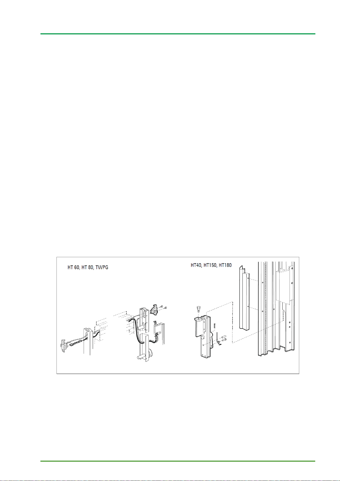
Diagram 1 Installation of the anti-drop device system
4.4 Reinstallation of the fall arrestors
Reinstall the fall arrestors in the correct position through the lower openings in the guide rail.
4.5 Inspection of the locking function
The anti-drop device system is tested for standard installation situations. Therefore, the fall arrestors must only
be still tested for proper locking.

Maintenance of the anti-drop device system
Butzbach GmbH Industrietore Originalbedienungsanleitung Absturzsicherung_V1 24/02/2021 4
Check the functioning of the fall arrestor with a free fall: Per regulations, the fall arrestors should lock into place
after a falling distance of approx. 150 mm (maximum permitted: approx. 300 mm). The spacing of the support
rails is as follows:
Type
Use in door types
AS HT40 / TW PG
50 mm
AS HT60/80
50 mm
AS HT80
65 mm
AS HT150
75 mm
Important! The fall arrestors must be easily movable over the entire length of the guide rail.
4.6 Connection and inspection of the automatic shut-off device
After installing the lower door panel with the two fall arrestors, the automatic shut-off device should be
connected and inspected as follows:
1. Connect the safety limit switch to the corresponding current collector. Important! Ensure that the
polarisation is correct in doors with built-in diodes.
The power supply is directed through a power chain in doors HT40, HT150 and HT180.
2. Attach the cover strip on the guide rail.
3. Reconnect the door system to the power supply and switch the power switch to position I (ON).
4. Place an object (at least 35 mm high) under the door to test the automatic shut-off device.
5. Operate the door with the "close door" button. A safety limit switch is attached to the bottom door
panel. As soon as the next door panel runs into the bottom door panel, the closing movement is
stopped and reverse is initiated. The limit switch is enabled when starting up the door. Afterward, the
motor switches off (depending on the setting: 2 seconds of moving freely or opens until the door OPEN
end switch is reached) and stops the door movement.
Warning!
The anti-drop device system is tested for standard installation situations. For this reason, the simulation of
a falling door to test the fall arrestation function is not necessary.
There is mortal danger to the operator in the case of an improperly conducted fall simulation and it can
lead to damage to the door system or other objects. The manufacturer shall accept no liability for damage
occurring due to this improper use!

Technical Data
Butzbach GmbH Industrietore Originalbedienungsanleitung Absturzsicherung_V1 24/02/2021 5
5 Technical Data
Description
AS HT40 / TW PG
AS HT60/80
AS HT80
AS HT150
Test certificate number
TorFV 8/135
TorFV 3/018
TorFV 3/019
TorFV 3/020
Max. permitted leaf weight
per pair
4,200 N
7,770 N
16,800 N
52,974 N
Max. operating speed
0.5 m/s
0.5 m/s
0.5 m/s
0.5 m/s
Stopping force per
guide rail
11,811 N
7,967 N
8,460 N
26,487 N
Guide rail
HT40 / TW PG
HT60, HT80/260
HT80
HT150
Drawing number
45 /058/4
45/ 148/4
45/ 105/4
45/ 081/4
Automatic shut-off device
By means of
overload protection
on both sides
Both sides
Both sides
Both sides

Index
Butzbach GmbH Industrietore Originalbedienungsanleitung Absturzsicherung_V1 24/02/2021 6
Index
A
Areas of use .................................................................1
Automatic shut-off device.........................................1, 4
C
Copyright.......................................................................I
D
Design..........................................................................1
Dismantling...................................................................3
F
Fall arrestors.................................................................3
Function........................................................................1
L
Locking function............................................................3
M
Maintenance.................................................................3
Masthead.......................................................................I
R
Reinstallation................................................................3
T
Technical Data..............................................................5
Testing..........................................................................2
Other manuals for SPACELITE HT40
1
This manual suits for next models
7
Table of contents
Other BUTZBACH Garage Door Opener manuals