manuals.online logo
Brands
  1. Home
  2. •
  3. Brands
  4. •
  5. Buyers
  6. •
  7. Controllers
  8. •
  9. Buyers SaltDog HV715EP User manual

Buyers SaltDog HV715EP User manual

1
TM
9049 Tyler Blvd. • Mentor, Ohio 44060
Phone (440) 974-8888 • Fax (440) 974-0165
Toll-Free Fax 800-841-8003 • saltdogg.com
Installation Instructions
HV715EP & HV1030EP
Electric-Hydraulic Spreader
Control
Fig. 1
—continued inside
Spreader Speed Controller
For Hydraulically driven Tailgate and V-Box
Spreaders using the HV715E/ HV1030E valve
manifold.
Fast Start Feature
When control unit is turned on, the controller
automatically starts at previous settings for
the Auger and Spinner. This makes starts
instantaneous without delay. The selected valve
position will be indicated on the LED panels as
0–10.
Auger-Blast Function
When the auger is being operated at less than
full power, the operator can deliver a “Blast” of
additional salt by depressing the front mounted
“Auger Blast” button. Ideal for laying more salt on
those “trouble spots.” The output to the Auger will
return to its preset speed after set time (which is
adjustable from 0-30 seconds) has elapsed.
WARNING
To prevent serious injury, always turn control off
and disconnect spreader from rear plug while
servicing or clearing jammed spreader.
The LED panel will indicate “BT” during this
function* the blast button will “illuminate” to
indicate that function has been activated.
Auger Automatic & Manual Function
When the auger "override" wire (blue wire on rear
of controller) is connected to +12VDC signal from
brake switch and "auger" switch is in the "on"
position, the auger will stop feeding product as
long as brake pedal is depressed. Auger speed
will return to original setting after brake pedal is
released. If auger switch is in the "off" position, this
disables this function.
Rear-Mounted Main Fuse
If the spreader valve or wiring harness becomes
damaged or shorted out, the main power fuse on
controller harness will “blow” shutting off power
to controller. The cause must be repaired before
replacing fuse. Use 5 amp fuse only.
Retrofit
The valve controller can be used with all Buyers’
Hydraulically driven Tailgate Spreaders, V-Box
spreaders as well as other brands. It’s easy to
upgrade or replace previous models.
2
TM
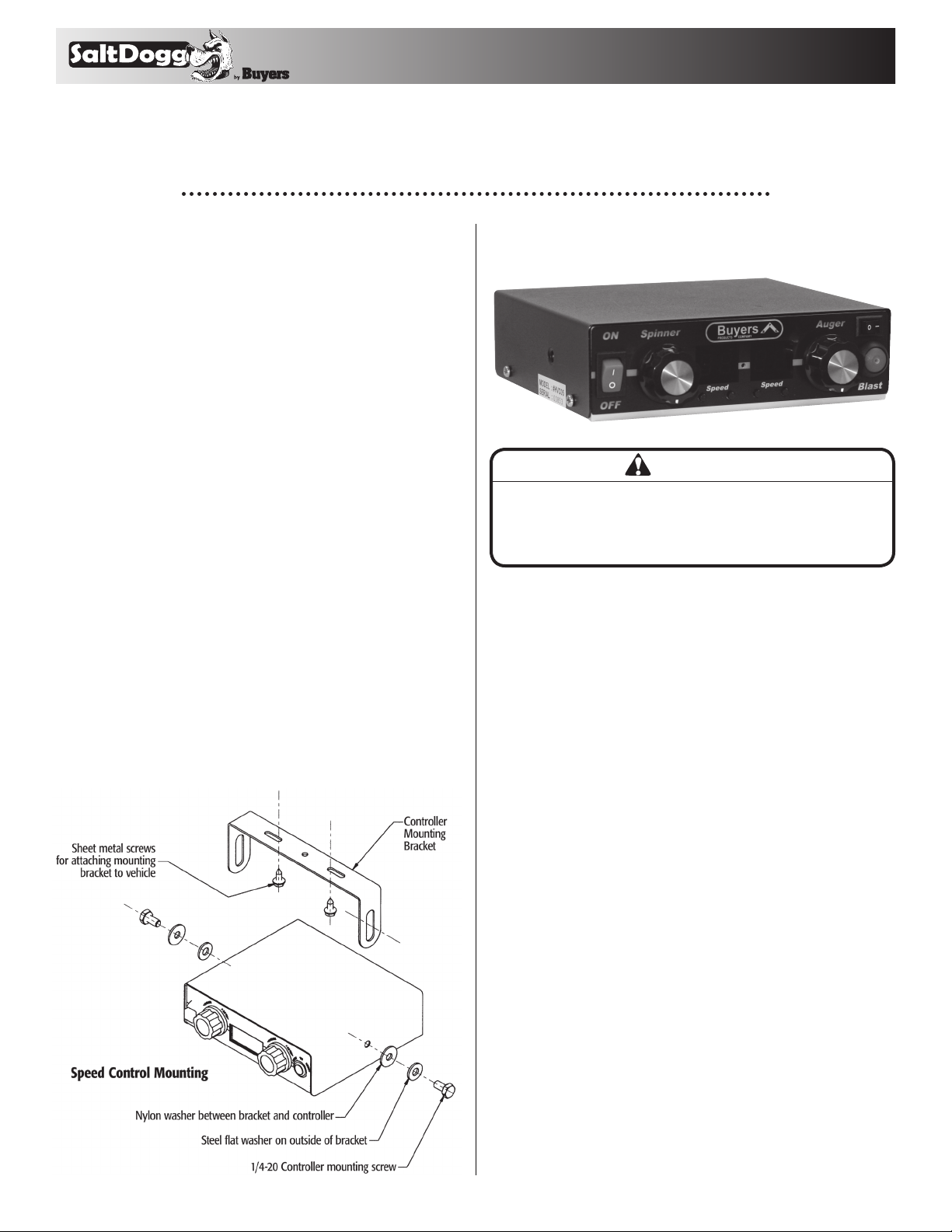
Adjusting Spinner Zero Settings
1. Verify that the spinner knob is turned completely
CCW to the zero position before beginning
adjustments.
2. Make sure that spinner disk has stopped, if it is
rotating, see step #3
3. Using a paperclip (that has been straightened
out) depress the "set" button that is located
between the two led displays on front of controller
to put controller into "adjustment mode".
4. Using the "speed" buttons below the spinner
display, press the "Right" speed button to decrease
the output to the spinner disk.
5. After spinner stops rotating, use the paper clip
to depress the "set" button to lock-in setting.
Adjusting Spinner Span Settings
1. Verify that the spinner knob is turned completely
CW to the max speed position you want before
beginning adjustments.
2. Check to see that spinner disk is spinning at
desired speed then proceed to step #3
3. Using a paperclip (that has been straightened
out) depress the "set" button that is located
between the two led displays on front of controller
to put controller into "adjustment mode".
4. Using the "speed" buttons below the spinner
display, press the "Left" speed button to increase
the output to the spinner disk if it is rotating to
slow.
5. After spinner is rotating at desired speed, use
the paper clip to depress the "set" button to lock-in
setting.
Adjusting Auger Zero Settings
1. Verify that the Auger knob is turned completely
CCW to the zero position before beginning
adjustments.
2. Make sure that Auger is stopped, if it is moving
proceed to step #3
3. Using a paperclip (that has been straightenened
out) depress the "set" button that is located
between the two led displays on front of controller
to put controller into "adjustment mode".
4. Using the "speed" buttons below the Auger
display, press the "Right" speed button to decrease
the output to the Auger motor.
5. After Auger stops moving, use the paper clip to
depress the "set" button to lock-in setting.
Adjusting Auger Span Settings
1. Verify that the Auger knob is turned completely
CW to the max speed position you want before
beginning adjustments.
2. Check to see that auger is moving at desired
speed then proceed to step #3
3. Using a paperclip (that has been straightened
out) depress the "set" button that is located
between the two led displays on front of controller
to put controller into "adjustment mode".
4. Using the "speed" buttons below the Auger
display, press the "Left" speed button to increase
the output to the auger until desired speed is
achieved.
5. After Auger is moving at desired speed, use
the paper clip to depress the "set" button to lock-in
setting.
Setting Blast Time
1. Check to make sure the Auger speed knob is
NOT turned to full speed before beginning blast
time adjustment.
2. Press the " blast button" on the front of the
controller to initiate the "blast" function.
3. Using the same paper clip that was used for
spinner and auger adjustments, depress the "set"
button between the two led displays to enter
setting mode.
4. The auger display will show "BT", using the
"speed" buttons below the auger display, press the
"left" button to increase the blast time or press the
"right" button to decrease the blast time.
5. Use paper clip,press the "set" button again to lock
in value.
3
TM
Fig. 2
TROUBLE-SHOOTING GUIDE
FOR THE VALVE CONTROL
SYMPTOM: VALVES NOT WORKING, LED IS BLANK
CAUSE: 1. GROUND WIRE (BLACK) IS NOT CONNECTED TO CHASSIS GROUND
2. IGNITION WIRE DOES NOT HAVE POWER
3. BLOWN POWER FUSE ON BACK OF CONTROLLER
SYMPTOM: VALVE NOT WORKING
CAUSE: 1. GROUND WIRE IS NOT CONNECTED TO VALVE
2. POSITIVE WIRE IS NOT CONNECTED TO VALVE
3. AUGER/SPINNER STALLED / LOCKED UP
NOTE:
ALL THREE WIRE MUST BE CONNECTED (INCLUDING THE
BLACK GROUND WIRE) IN ORDER FOR THE CONTROLLER
TO WORK PROPERLY.
VALVE CONTROL
REAR VIEW
RED AUGER +
GREEN AUGER -
BLACK SPINNER -
WHITE SPINNER +
WHITE TO FUSED/KEYED 12VDC
BLACK TO GROUND
RED TO BATTERY +
ROUTE UNDER VEHICLE TO CONTROL VALVE UNIT
(P/N- HVH15)
RED TO
POSITIVE TEMINAL
BLACK TO NEGATIVE
BATTERY TERMINAL
(HVH8)
WHITE TO FUSED +12VDC
POWER SWITCHED THRU
IGNITION KEY
TO SPINNER COIL
IN HVB
(BLACK / WHITE)
WIRE CONNECTOR TO AUGER COIL
IN HVB
(RED / GREEN)
WIRE CONNECTOR
CONTROL MOUNTED UNDER DASHBOARD OF VEHICLE
OR CONSOLE (P/N - HVC05)
4
TM
9049 Tyler Blvd. • Mentor, Ohio 44060
Phone (440) 974-8888 • Fax (440) 974-0165
Toll-Free Fax 800-841-8003 • saltdogg.com
3011514 Rev. J
WARRANTY
Buyers Products Co. warrants all truck/trailer hardware manufac-
tured or distributed by it, to be free from defects in material and
workmanship for a period of one year from date of shipment. Parts
must be properly installed and used under normal conditions. Any
product which has been altered, including modification, misuse,
accident or lack of maintenance will not be considered under
warranty. Normal wear is excluded. The sole responsibility of
Buyers Products Co. under this warranty is limited to repairing or
replacing any part or parts which are returned, prepaid, and are
found to be defective by Buyers Products Co. Authorization from
Buyers Products Co. must be obtained before returning any part.
No charges for transportation or labor performed on Buyers’ prod-
ucts will be allowed under this warranty.
Parts List
1 HV715E HV1030E Valve, Spreader, Electric
1 3016036 3016036 Box, HV715E/HV1030E
1 HVC05 HVC05 Controller, HV715EP or HV1030EP
1 HVH15 HVH15 Harness, Wire 15'
1 HVH8 HVH8 Harness, Wire 8'
1 3016035 3016035 Bracket HV715E/HV1030E
2 FSH025020400 FSH025020400 Screw, Socket HD Cap 1/4" x 4" LG
2 FWF025063007 FWF025063007 Washer, Flat 1/4" SAE ZN
2 FNE025020031 FNE025020031 Nut-Elastic Stop 1/4"-20 ZINC
4 FSH010032075 FSH010032075 Screw, Socket HD Cap, 10-32 x 3/4" PL
1 3011514 3011514 Instruction Sheet, HV715EP/HV1030EP
1 3016037 3016037 Gasket
qty HV715EP HV1030EP dEscriPtion
Hydraulic Schematic
shown with 11 GPM Directional Valve Bank
1
12
13
12
2
PLOW UP & DOWN
INLET
Flow Divider not required
if you have a directional
valve that is rated at
20 GPM or more
In Line Relief set at 1600 PSI
required if system pressure
(main relief) is set higher
than 2250 PSI
OUTLET
DUMP
PLOW ANGLE
3
4
5
11
10
A
S
8
79
6
3/4"
3/4"
3/4"3/4"
3/4"
3/4"
3/4"
1/2"
1/2"
3/4"
3/4"
3/4"
3/4 3/4"
3/4"
1-1/4"
1-1/4"
3/4"
PB 6
1- RESERVOIR
2- PUMP
3- VALVE (HVE344PB Shown)
4- FLOW DIVIDER
5- VALVE, SPREADER
6- QUICK DISCONNECT 3/4"
7- QUICK DISCONNECT 1/2"
8- MOTOR, AUGER
9- MOTOR, SPINNER
10- GAUGE
11- FILTER
12- VALVE, BALL
13- RELIEF VALVE, IN LINE
PT

This manual suits for next models

1

Popular Controllers manuals by other brands

Pioneer DDJ-ERGO Setting file import guide

Pioneer

Pioneer DDJ-ERGO Setting file import guide

Epson S1D13700 manual

Epson

Epson S1D13700 manual

Redback A 4500B operating manual

Redback

Redback A 4500B operating manual

Graco 24W482 instructions

Graco

Graco 24W482 instructions

Belimo HR series quick start guide

Belimo

Belimo HR series quick start guide

TAC Xenta 110-D/24 installation instructions

TAC

TAC Xenta 110-D/24 installation instructions

Elk Products ELK-MM443 quick start guide

Elk Products

Elk Products ELK-MM443 quick start guide

nekos ROCK 230 V instruction manual

nekos

nekos ROCK 230 V instruction manual

Chamberlain 945C Owner's instructions

Chamberlain

Chamberlain 945C Owner's instructions

TWR Lighting D-1LVS manual

TWR Lighting

TWR Lighting D-1LVS manual

Banner MSDINT-1L2 instruction manual

Banner

Banner MSDINT-1L2 instruction manual

Newport LDS1000 user manual

Newport

Newport LDS1000 user manual

Bornay WIND+ manual

Bornay

Bornay WIND+ manual

Intelligent Actuator IS-D CR operating manual

Intelligent Actuator

Intelligent Actuator IS-D CR operating manual

ABB IRC5 Compact product manual

ABB

ABB IRC5 Compact product manual

Conrad 64 05 52 operating instructions

Conrad

Conrad 64 05 52 operating instructions

Ozroll SOLAR PRO II manual

Ozroll

Ozroll SOLAR PRO II manual

Allen-Bradley Logix5000 Series Application book

Allen-Bradley

Allen-Bradley Logix5000 Series Application book

manuals.online logo
manuals.online logoBrands
  • About & Mission
  • Contact us
  • Privacy Policy
  • Terms and Conditions

Copyright 2025 Manuals.Online. All Rights Reserved.