BYD BMU User manual

BMU
Applicable to Battery-Box HV
QUICK INSTALLATION GUIDE
2020/03/23
V 2

Overall structure
Tools
Skilled personnel only.
This manual and the tasks and procedures described herein are intended for use by skilled workers only.
A skilled worker is defined as a trained and qualified electrician or installer who has all of the following skills and experience:
• Turn off all power before operating.
• Knowledge of the functional principles and operation of on-grid systems.
• Knowledge of the dangers and risks associated with installing and using electrical devices and acceptable mitigation methods.
• Knowledge of the installation of electrical devices.
• Knowledge of and adherence to this manual and all safety precautions and best practices.
• Before installing BMU,make sure all the system’s switches of BCU are switch off.
Important
Installation environment requirements
Max.
+50℃
Min.
-10℃
Fire-resistant locations only
(Concrete/Drywall/Exterior
Siding Etc)
Flammable Materials,
Gas,Furnace,Etc.
RH.
+5%~+95%
Packing list
1×Wall-mounted 3×Adapter cable3×Hexalobular socket screw
Yes
YES NO
NO
Front panel
Indicator light
Power cable input
Power cable output
Communication cable output
p
cab
le
Wall-mounted
Restart button
Churn drill
Please update the BCU software to the V3.013C or V3.013R or newer firmware Before installing.
Indoor installation Outdoor installation
Torx screwdriver(T20)
2× Expansion bolt

1. 2.
3. Overview
Installation steps
4. Connect adapter cable
Install BMUInstall Wall-mounted
P+
P+
COM
WAN
P-
Install the adapter cable inside the BCU.
φ=9mmL=40mm
BATBATBATWAN
Inverter
12V
GND
RS485A
RS485B
EARTH
11V_IN+
11V_IN-
CAN2H
CAN2L
NC
BATBATBATWAN
Inverter
12V
GND
RS485A
RS485B
EARTH
11V_IN+
11V_IN-
CAN2H
CAN2L
NC
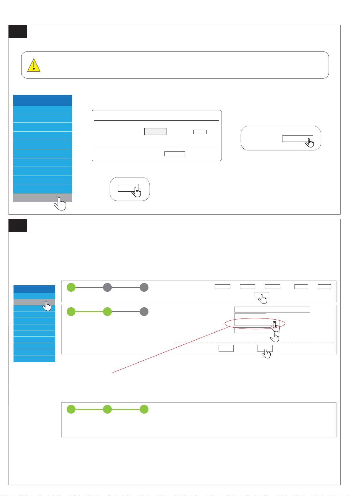
5a. Update the firmware of BCU before connect BCU to BMU.
Battery-Box HV
Privacy Policy
Home
Device Information
Installation Config
Statistics Information
Current Alarm
History Alarm
Run Date
Set Password
Update
1 32
STEP 1 STEP 2 FINISH & REBOOT
1 32
STEP 1 STEP 2 FINISH & REBOOT
Time and Date *Hour : Min : Day : Month : Year :
Next
Installation
Server IP Address *
Series Battery Conts *
Inverter *
Country *
Asterisk(*)Indicates required fields
bboxhserver.byd.com.cn
PARALLEL
1 32
STEP 1 STEP 2 FINISH & REBOOT
Last Next
Reboot System…
Please wait about 50 seconds.
5b. Set parameters for BCU
Battery-Box HV
Privacy Policy
Home
Device Information
Installation Config
Statistics Information
Current Alarm
History Alarm
Run Date
Set Password
Installtion
Update
Update
Please input the file : Upload
If there is any new version on the server, clicking UpdateCheck will update the syetem.
Search...
Please input file: Search
Upload
Made sure each BCU to select "inverter" as "PARALLEL", otherwise the parallel connection will fail.
At a minimum, upgrade the firmware of the BCU to V3.013C or V3.013R, otherwise
the next step cannot be performed.
Select the inverter type on BCU before the BCU - BMU - Inverter connected.
Connect the BCU’s WIFI (According to BCU's quick installation guide.)
P+
COM
WAN
P-P+
COM
WAN
P-
P+
COM
WAN
P-
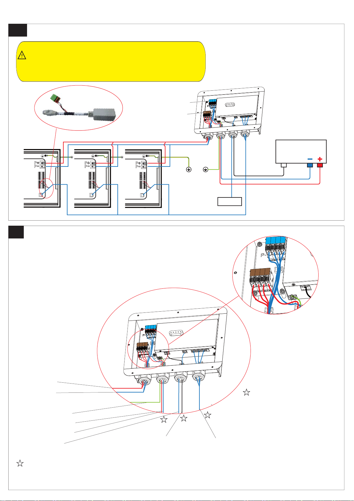
6a. Connect cables
6b. Connecting information
Inverter
com
Router
BCU1 BCU2 BCU3
BMU
To BCU+
To Inverter D+
To Inverter D-
To Inverter communication
To Router To adapter cables(inside the BCU)
To BCU-
To Ground
Please refer to the inverter installation manual and the Battery-Box HV installation manual or related
manual.
Recommended the cables type is
RJ-45(T568B) , otherwise it may
not pass through
(Shielded Twisted Pair)
Supports up to 3 BCUs in parallel.
The number of battery modules connected to each BCU must be unique.
The BCU ground cable is not allowed to be connected to the BMU and
must be connected to the public ground of the home.Other wise,there may
be communication problem between the BCU and BMU and could be cause
the battery system to undervoltage or overdischarge
(The PIN definition is the same as the
BCU of the Battery-Box HV)
P+
P-

7a. Connect via the wifi of BMU
7b.
192.168.100.1
192.168.100.1
WLAN
BYDxxx
network 1
network 2
BYDxxx
123456789
cancel login
BYDxxx
Username installer
cancel login
Password byd@12345
WLAN password
ON
192.168.6.1.
192.168.6.1
BYDxxx
Username installer
cancel login
Password byd@12345
Connect via the ethernet cable
①Connect the network cable
②Set your computer IP into a static IP
IP address:192.168.6.10
Subnet mask:255.255.255.0
Setting method reference computer system setting method
③
④
ON
8. Setup system information of BMU
Battery-Box HV
Privacy Policy
Home
Device Information
Installation Config
Statistics Information
Current Alarm
History Alarm
Run Date
Set Password
Update
1 32
STEP 1 STEP 2 FINISH & REBOOT
Time and Date *Hour : Min : Day : Month :
Next
Installation
Server IP Address *
Devices:
Series Battery Counts *
Array counts *
Inverter *
Country *
Asterisk(*)Indicates required fields
bboxhserver.byd.com.cn
SMA
Previous Finish Refresh
Fill in the quantity of BCU
Fill in the quantity of Battery module of each BCU
These parameters is important.
Please make sure the correct configuration for these parameters,
otherwise the system might not work normally.
NO
1
2
3
SN
100251808-00002
100251808-00033
100251808-00065
192.168.100.100
192.168.100.101
192.168.100.102
IP
Turn on all the
system switch
Please make sure to finish step 5 in this guide.
Recommended connecting method
Optional connecting method
SN of parallel-Box
Note:
Array counts *3
If this value is different from the exact quantity,
Please press the button(Refresh) or check the battery connection.
9. Setup system information
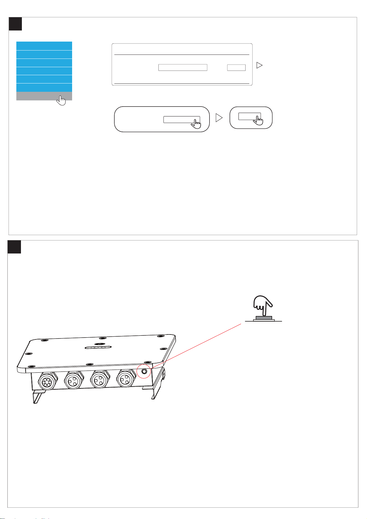
10. About Button
Installation Config
Statistics Information
Current Alarm
History Alarm
Run Date
Set Password
Please input file:
Upload
Update
Please input the file : Upload
Search
Search
Update
Press the button T=Pressing Time
1S<T<5S Turn on /Turn off the WIFI of BMU
5S<T<10S reset password of WIFI of BMU
T>15S first and then Press 1S, Restart the BMU
*The BMU’s WIFI not power off automatically,But you can turn it off manually.
*The software version can only be upgraded and cannot be downgraded.

11. Information of Light
12. About SN.
1 2 3 4 5 STATUS
GREEN
COLOUR
RED
1%≤SOC≤20% (If SOC<1%, all the lights are off.)
20%<SOC≤40%
40%<SOC≤60%
60%<SOC≤80%
SOC>80%
The first BCU* have the alarm.
The 2nd and 3rd BCU* have alarms.
Wrong battery quantity configuration.
BCU firmware version is inconsistent.
LED off
LED blink
LED illuminated
100251808-00002
100201908-00001
100201908-00001
100441808-00999
100441808-00999
100201908-00003 100201908-00003
YearWeeks Sequence number
1 32
*The BCU will be numbered from small to large SN.
Rank the SN.(Year weeks sequence number)
Before sorting After sorting
First
Second
Third
Table of contents
Popular Controllers manuals by other brands

Digiplex
Digiplex DGP-848 Programming guide

YASKAWA
YASKAWA SGM series user manual

Sinope
Sinope Calypso RM3500ZB installation guide

Isimet
Isimet DLA Series Style 2 Installation, Operations, Start-up and Maintenance Instructions

LSIS
LSIS sv-ip5a user manual

Rockwell Automation
Rockwell Automation 1769-L31 installation instructions


