BYONICS DTMF Remote User manual

DTMF Remote Manual
Version 0.5 – June 28, 2019
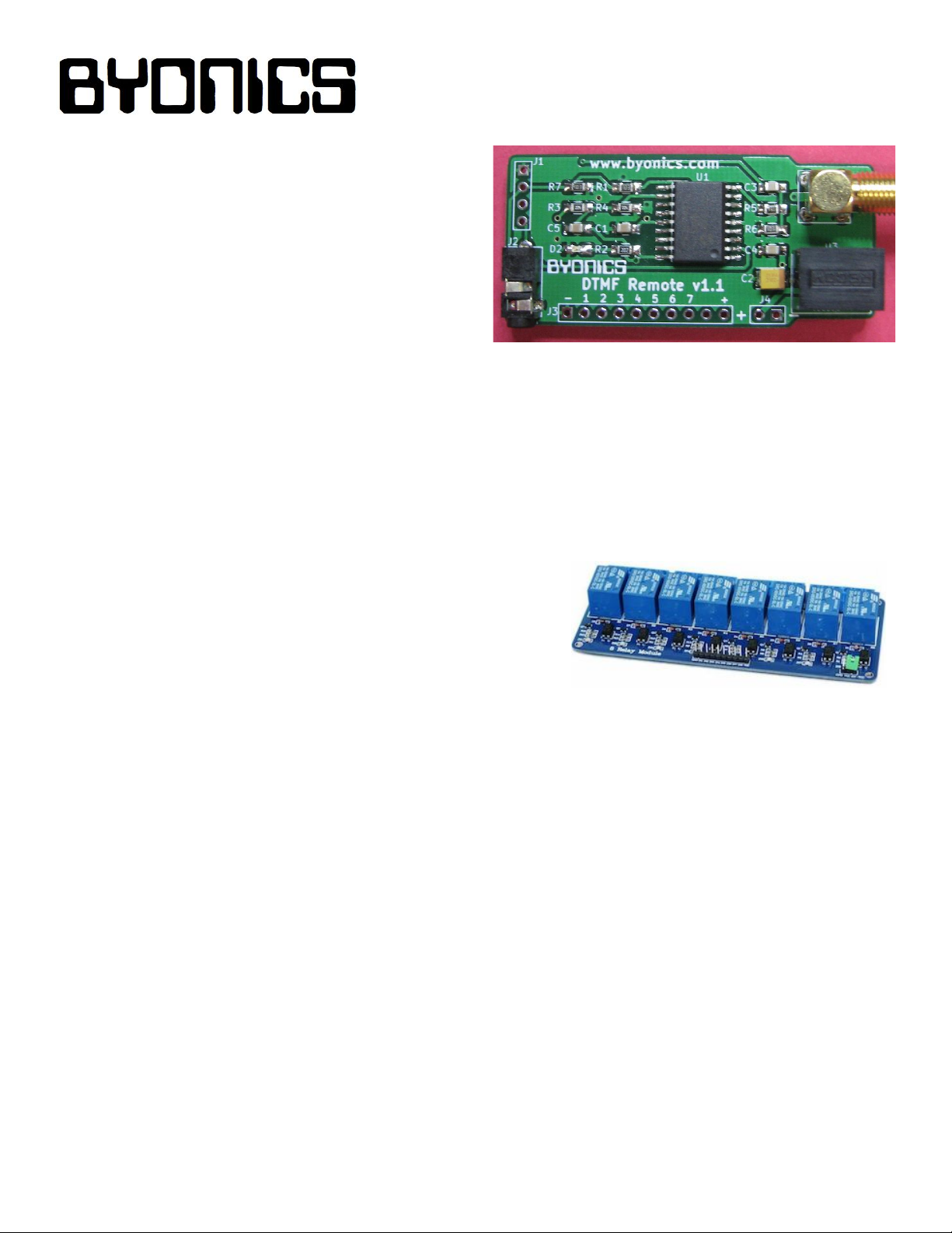
Overview
The Byonics DTMF Remote is a miniature DTMF
decoder intended for remote control applications. It
includes a VHF transceiver and password
controlled access to seven digital output lines. The
DTMF Remote can be configured with any terminal
program and can optionally transmit a tone
sequence to acknowledge receipt of a command.
Typical applications are high-altitude balloon cut-down commands, remote rocket ignition, and high
power relay controls for remote sites such as repeaters or digipeaters.
Receiver
The Byonics DTMF Remote can be accessed via any VHF transmitter with a DTMF keypad operating
between 135 and 174 MHz. Options for password protection, frequency choice, and DCS or CTCSS
decoding provide for a high level of protection from intentional or accidental access.
Outputs
The Byonics DTMF Remote has seven logic level outputs
that may be momentary or latched, and can be globally
configured as active high or active low. It was designed to
optionally use low-cost eBay relay boards for AC and high
power operations. The highly efficient switching power supply on the decoder provides power through
a ten-pin ribbon connector cable (not included) to source up to one ampere for the relay board.
Command Acknowledgement
The DTMF Remote can transmit a tone sequence to identify and confirm received commands. The
tones are followed by an amateur radio callsign in Morse code. Note that the remote can receive
between 135 and 174 MHz, but it will only transmit in the amateur radio 2-meter band. The RF output
of the transmitter is nominally 1 watt and an amateur radio license is required to utilize this feature.
LED
The DTMF Remote includes an LED to indicate the status of the unit. The LED will be on solid when
transmitting, flash quickly when receiving DTMF tones, and flash slowly when locked.
Power Wiring
The DTMF Remote is powered with 8-28V DC applied to the J4 port. Current draw is about 320mA
during transmit, 30mA when receiving, and 10mA when idle.

Configuration
The Byonics DTMF Remote is configured via the 2.5mm TRS serial I/O jack J2 using the Byonics
USB-2.5 or DB9-2.5 cable. It can also be configured and powered via the 1x4 serial & power holes
marked J1 using the Byonics USB-TTL cable. Pin 1 of J1 is the corner square pad for ground/black,
pin 2 is serial in/green, pin 3 is 5V/red and pin 4 is serial out/white. Since J1 can provide power,
powering via J4 is not necessary. It is not necessary to solder a connector to J1, just insert the pins
and slightly tilt to make a good contact. Any computer and operating system with a terminal program
can be used. In addition to controlling the digital outputs, any decoded DTMF tone or sequence will
be output through the serial port.
To access the configuration menu, set a terminal program to the
corresponding COM port, set the parameters to 9600 baud N81
and connect the cable to either J2 (2.5mm) or J1 (1x4). If using J2,
apply power via port J4. The product name and firmware version
should appear in the terminal. Press ESC and the config menu
shown on the right will appear with the current value shown after
each setting. Enter the number of the setting to be changed, press
Enter, and then enter the new value and press Enter. After setting
all desired options, cycle power to return to normal operation.
Byonics DTMF Remote v0.7
Config Menu
1>RX Freq (144.3300)
2>RX Tone (0)
3>RX Powersave (0)
4>TX Enable (0)
5>TX Freq (144.3300)
6>TX Tone (0)
7>TX ID (DTMF)
8>Unlock Code (12345)
9>Active Low (0)
Enter Selection>
1> RX Freq - Enter a frequency from 135 to 175MHz using all four digits after the decimal point
2> RX Tone - Enter a value from 1 and 121 to select CTCSS or DCS decoding, or 0 to disable
3> RX Powersave - Enter 1 for periodic receiver sleep, or 0 for continuous receive
4> TX Enable - Enter 1 to enable transmission acknowledgements, 0 to disable
5> TX Freq - Enter a frequency from 144 to 148MHz using all four digits after the decimal point
6> TX Tone - Enter a value from 1 and 121 to select CTCSS or DCS encoding, or 0 to disable
7> TX ID - Enter an amateur radio callsign to legally identify the transmissions
8> Unlock Code - Enter an up to 6 digit number as a security key
9> Active Low - Enter 1 for active low outputs (inverts all outputs), 0 for active high outputs
DTMF Commands and Response
There are five commands used to control the DTMF remote and its outputs. These are transmitted by
holding down the controlling radio PTT switch, and pressing the appropriate DTMF key.
●DTMF A key followed by a series of number keys 1-7 - Sets the corresponding outputs HIGH
as long as the DTMF number key is sent. The output returns to low when the DTMF number key
is released. If enabled, the remote will respond with a number of beeps indicating the last
switched output followed by the Morse ID.
●DTMF B key followed by a series of number keys 1-7 - Sets the corresponding outputs high,
and leaves them in that state (latching). If enabled, the remote will respond with a number of
beeps indicating the last latched output, then a higher beep, followed by the Morse ID.

●DTMF C key followed by a series of number keys 1-7 - Sets the corresponding outputs LOW,
and leaves them in that state (latching). If enabled, the remote will respond with a number of
beeps indicating the last latched output, then a lower beep, followed by the Morse ID.
●DTMF STAR - Locks unit to prevent any operations. If enabled, the remote will respond with a
decreasing tone sequence, followed by the Morse ID.
●DTMF STAR followed by unlock code - Unlocks unit and allows for the above operations. If
enabled, the remote will respond with an increasing tone sequence, followed by the Morse ID.
Notes
● Attempting to control output 9 will control output 1. Attempting to control output 0 or 8 will have
no effect.
PCB
Schematic
Table of contents
Other BYONICS Media Converter manuals