77
MAINTENANCE
SPRAYER
The unit has the following user-serviceable parts: the liquid lter, the nozzle assembly, and the battery pack. Nothing
inside the unit housing is user-serviceable. Do not open the unit shell as doing so will VOID the warranty on the gun.
Contact your ByoPlanet® Service Representative at (855) 211-1518.
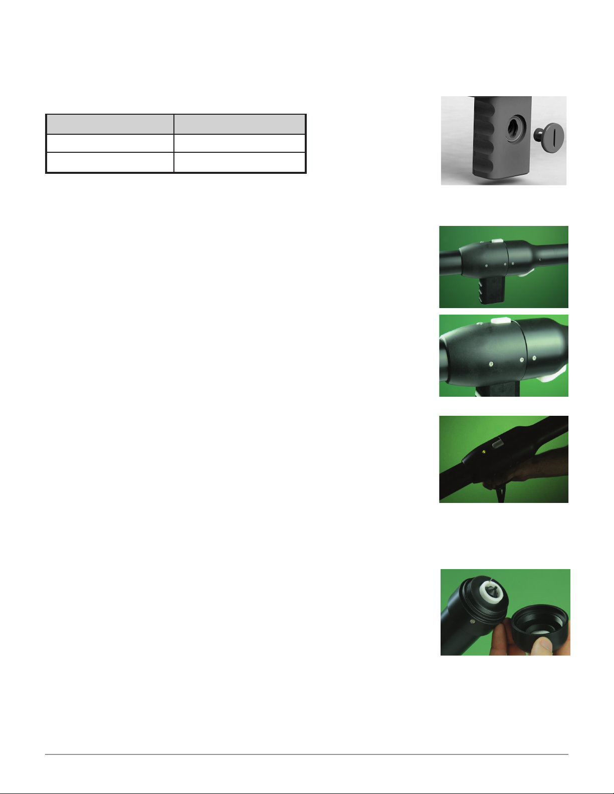
LIQUID FILTER
The liquid lter assembly is located on the side of the unit handle. Use an appropriate spade
tool, or coin, to access for service. To remove, align the slot with the two features around the
lter. After doing so, simply turn the unit on its side and it should fall right out. Inspect the
lter screen for contaminates and clean if required. Upon reinstallation, verify that the two
O-rings are in place and free of contaminates that may cause an insufcient seal. To reinsert,
align the features as before and rotate 90* in either direction.
NOZZLE
Cleaning the Nozzle
The most important thing you can do to ensure trouble-free operation of your unit is to rinse the nozzle out with clean
water after every use. By cleaning your gun’s nozzle after each usage, you will avoid the long-term chemical buildup
that eventually causes clogs, poor spray patterns, and shortened life of the nozzle components.
In addition to rinsing with clean water after each use, the nozzle should periodically
be dissembled and cleaned. Your nozzle maintenance schedule will vary depending
on how often the gun is used and adherence to pre/post-spray checks.
It is recommended to contact ByoPlanet before performing the service outlined below.
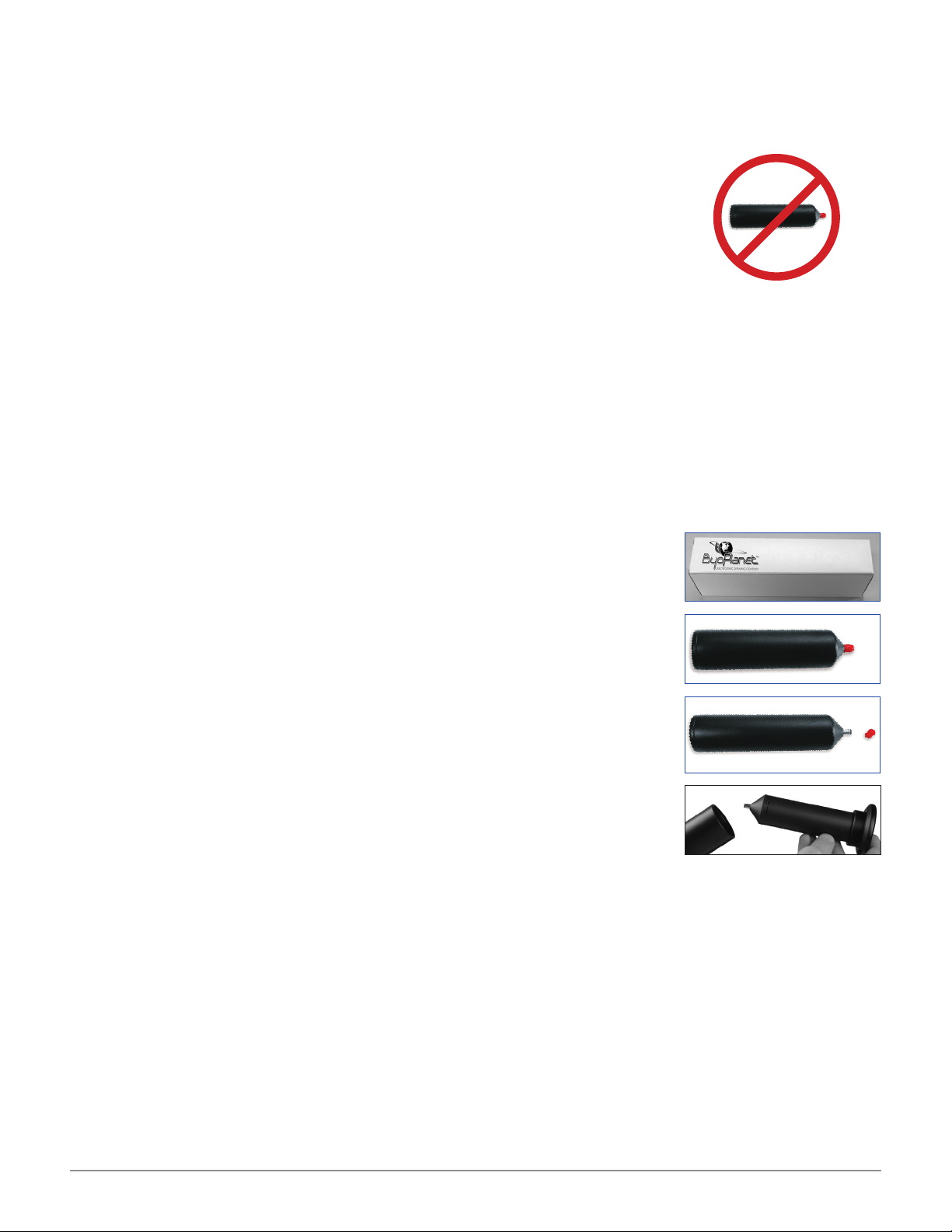
To Clean/Inspect the Nozzle Assembly:
1. With the unit disconnected from the base unit, unscrew the cover from the
nozzle base. Clean any debris from or around any of the interior surfaces
with warm water.
2. Inspect for any damage to the liquid tip. If spray pattern was noted to be
inconsistent or non-typical of a healthy symmetrical spray, remove the liquid
tip with an appropriate 7/16" socket wrench.
3. Inspect Nozzle electrode for any signs of electrical arching, burn and/or
corrosion. Gently push down on the electrode to verify a smooth spring return.
If any issues are noted remove/replace immediately. This is done by gently
pulling on the electrode with a pair of pliers. Otherwise service the electrode
by applying a generous amount of dielectric grease. Available at any local
automotive/hardware store.
4. Be sure to also thoroughly clean all interior surfaces of the nozzle cover;
including the main orice.
IMPORTANT NOTE: The nozzle
cover should be hand tight. Never
use pliers or other tools to tighten
it, as this may cause damage.
Removal of the nozzle electrode
is not necessary for cleaning.
PURGING
To Clean/Inspect the Nozzle Assembly:
1. Disconnect the liquid hose line (smaller connector) from the sprayer handle.
2. With the base unit (CS-900 or BP-500) powered on, and the liquid hose line
disconnected, depress the sprayer trigger to emit liquid.
3. Continue to depress the trigger until the sprayer no longer emits liquid.
4. Place the sprayer in the holster to prepare the equipment for storage or its
next use.
The ES-120 Electrostatic Sprayer should be purged of chemistry after every use.