C.E.C. DA 0 3.0 User manual

DA 0 3.0
D/A CONVERTER
Owner's Manual
POWER MUTE MENU SELECT
DIGITAL TO ANALOG CONVERTER DAO 3.0

DIGITAL TO ANALOG CONVERTER DA 0 3.0 DA 0 3.0 User's Manual
2 3
Introduction …………………………………………………………………………………………… 2
Features………………………………………………………………………………………………… 2
Important Safety Instructions ………………………………………………………………………… 3
Unpacking and Installation …………………………………………………………………………… 5
Front Panel Functions ………………………………………………………………………………… 6
Back Panel Functions ………………………………………………………………………………… 7
"SUPERLINK" Digital Signal Transmission ………………………………………………………… 8
Remote Control unit…………………………………………………………………………………… 9
Operation …………………………………………………………………………………………… 10
Specications ……………………………………………………………………………………… 13
Contents
Thank you for purchasing a DA 0 3.0.
Please read through and refer to this Owner's Manual to use your DA 0 3.0 safely and
adequately.
It is recommended to keep the packaging available for future transportation needs.
Introduction
Important Safety Instructions
Features
▷The DA 0 3.0 is a universal DAC with some advanced DSP functions supporting up to
32bit/384kHz audio data rates.
▷
The 7 digital inputs covering all popular interface formats
▷Two sets of analogue outputs - RCA and XLR
▷
Re-Clocking for synchronizing incoming data to internal clock reference generator
▷Upsampling incoming data to 32bit 356/384kHz – two algorithms
▷Selectionoffourdigitallterswithdifferentimpulseresponse
▷Transformer decoupled I/O and power supplies
▷True balanced interface
CAUTION
RISK OF ELECTRIC SHOCK!
DO NOT OPEN!
CAUTION: TO REDUCE THE RISK OF ELECTRIC SHOCK,
DO NOT REMOVE THE COVER OR REAR PANEL. IT DOES
NOT CONTAIN ANY USER-SERVICEABLE PARTS. REFER
SERVICING TO QUALIFIED SERVICE PERSONNEL.
The exclamation point within an equilateral triangle is intended to notify the
user to the presence of important operating and maintenance (servicing)
instructions in the accompanying documentation.
The lightning flash with arrowhead symbol, within an equilateral triangle, is
intended to alert the user to potential electric shock hazards within the product’
s enclosure.
WARNING: TO PREVENT FIRE OR SHOCK HAZARD, DO NOT
EXPOSE THIS APPLIANCE TO RAIN OR MOISTURE.
1) READ ALL INSTRUCTIONS: All the safety and operating instructions of your Thrax Audio
equipment should be read before power is applied to the equipment.
2) RETAIN OWNER'S MANUAL: These safety and operating instructions should be retained
for future reference.
3) HEED WARNING: All warnings on the unit and in the operating instructions should be
adhered to.
4) FOLLOW INSTRUCTIONS: All operating and use instructions should be followed.
5) CLEANING: Unplug the unit from the wall outlet before cleaning.
6) VENTILATION: Do not install near any heat sources such as radiators, heat registers,
stoves,orotherdevices(includingampliers).Theunitshouldnotbe installed in a built-in
location such as a bookcase or rack unless proper ventilation is provided.
7) GROUNDING: Do not defeat the safety purpose of the grounding-type plug. A grounding-
type plug has two blades and a third grounding prong. The third prong is provided for your
safety.Iftheprovidedplugdoesnottintoyouroutlet,consultanelectricianforreplacement
of the obsolete outlet.

DIGITAL TO ANALOG CONVERTER DA 0 3.0 DA 0 3.0 User's Manual
4 5
8)
POWER CORD PROTECTION: Protect the power cord from being walked on or pinched
particularly at plugs, convenience receptacles and the point where they exit from the unit.
9) LIGHTNING: Unplug this unit during lightning storms or when unused for long period of
time.
10) SERVICING: Refer all servicing to qualified service personnel. Servicing is required
when the unit has been damaged in any way, such as if the power-supply cord or plug is
damaged, liquid has been spilled inside the appliance or it has been exposed to moisture,
the appliance does not operate normally, or has been dropped.
11)
DO NOT OPEN THE CABINET: There are no user serviceable
components inside this product. Opening the cabinet may present
ashock hazard and anymodicationtotheproduct will void your
warranty.
12) WARNING:Toreducethe risk ofreorelectricshock, do notexposethisunit to rain or
moisture.
CAUTION:
▷DO NOT EXPOSE THIS APPLIANCE TO DRIPS OR SPLASHES.
▷DO NOT PLACE ANY OBJECTS FILLED WITH LIQUIDS, SUCH AS VASES, ON THIS
APPLIANCE.
▷DO NOT INSTALL THIS APPLIANCE IN A CONFINED SPACE, SUCH AS WITHIN A
BOOKCASE OR SIMILAR PIECE OF FURNITURE.
▷PLUG THE AC POWER CORD INTO AN EASILY ACCESSIBLE AC WALL OUTLET,
SO IT CAN BE QUICKLY UNPLUGGED IN CASE OF EMERGENCY.
▷DO NOT REMOVE THE PROTECTIVE HOUSING WITH A SCREWDRIVER.
▷USE OF CONTROLS OR ADJUSTMENTS OR PERFORMANCE OF PROCEDURES
OTHER THAN THOSE SPECIFIED HEREIN MAY RESULT IN HAZARDOUS
RADIATION EXPOSURE.
▷
IF THIS APPLIANCE SEEMS TO BE MALFUNCTIONING, CONTACT A QUALIFIED
SERVICE STATION. DISCONTINUE USE OF ANY MALFUCTIONING UNIT.
Unpacking and Installation
This section describes the unpacking and installation procedures for your new component.
❶Unpacking
All shipping boxes have been specially designed to protect their contents and
special care has been taken to prevent damage under normal shipping conditions.
Mishandling should be evident upon inspection of the shipping container. Carefully
remove your new component from its packing and examine it closely for signs of
shipping damage. We strongly recommend saving all original packing to protect your
component from damage should you wish to store it or ship it at a later date.
❷Installation
▷BE CERTAIN TO INSTALL THE UNIT IN A SECURE LOCATION FROM WHICH IT
CAN NOT FALL OR TIP OVER
▷
Provide adequate ventilation - the chassis will become warm in normal use. Do not
operateoncarpetoranyothersurfacethatmightblockairow
▷Do not allow the chassis to touch any metal parts, such as the frame of an
equipment rack. This might create a parallel ground path that could degrade the
sound of your system
▷
Connect the input and output cables. Input connection is via COAX , AES/EBU
TOSLINK or USB. Output can be via RCA or XLR jacks
IMPORTANT: READ THE SECTIONS “BACK PANEL”
WARNING: The unit should be operated only at rated voltage, indicated on the
power connector. If you are not sure what is the mains voltage supplied to your
home, consult with your unit dealer.
▷
Connect the power supply to the power source indicated on the rear panel.
Avoid power conditioners that float the ground pin. ALWAYS connect power
cord to component before plugging it into an AC outlet, and make sure that
unit main switch is set to the „off” position before making the final connection.
For best performance, try to route the power cord away from signal cables.
Pay close attention to power quality, and be aware that different power cords can alter
the sound.
Important Safety Instructions
AC POWER CORD CONNECTION
CAUTION:
TO PREVENT ELECTRIC SHOCK, MATCH THE BLADE
WIDTH OF THE PLUG TO THE SLOT WIDTH. THE PLUG
MUST BE FULLY INSERTED TO THE SLOT.
For CANADA

DIGITAL TO ANALOG CONVERTER DA 0 3.0 DA 0 3.0 User's Manual
6 7
Back Panel Functions
IEC Power Connector, Main Switch, Fuses and Input Voltage Selector
There are fuses located in the IEC power connector on the back panel. For 230
volts operation a 0.63 amperes “Slow Blow” fuse is used. For 115 volts operation
the fuse should be 1.25 amperes. If power does not come on, contact your
authorized service representative.
Inputs
▷
2 x COAX jacks, labeled 1 and 2, accommodate signal from digital sources,
good for short runs and lower frequencies
▷
2 x TOSLINK inputs, labeled OPT 1 and OPT 2, provide ground isolation
between the units and noise immunity over long runs
▷
2 x AES/EBU inputs, labeled AES 1 and AES 2 to accommodate high quality
signal, that uses professional protocol
▷
1 x USB input (optional), Currently a USB – input is available to accommodate
digital signal from a computer source
Outputs
▷
Two sets of analog output jacks are provided – a pair single-ended RCA
outputs and a pair of balanced XLR outputs.
The switch between them activates the output selected.
Front Panel Functions
“ON/OFF” Button
Switches the unit “ON” and “OFF”. See OPERATION SECTION for details
“MUTE” Button
This button toggles between mute and normal volume modes. When the indicator
above the mute button is green the system is muted
“MENU” Button
Switches between menu and normal operation
“ENTER” Button
Validates the option selected
“MENU” Knob
Scrolls through the menu
LED Display
Shows the input selected, the signal sample/bit rate and the menu options. This display
is auto dimmable – goes off in few seconds if no control is operated. It automatically
goes on at power up, in case the input signal changes or user menu is selected
COAX Inputs
TOSLINK Inputs
AES/EBU Inputs
RCA Outputs
SWITCH RCA/XLR
XLR Outputs
REFER SERVICING TO QUALIFIED SERVICE PERSONNEL ONLY.
NO USER SERVICEABLE PARTSINSIDE.
RISK OF ELECTRIC SHOCK
DO NOT OPEN
ANALOG OUTDIGITAL INPUT
DIGITAL TOANALOG
CONVERTER
Model: CEC DA 0 3.0
CEC International GmbH
Handmade in EU
SERIAL NO.: DA 16040026
USB LAN
COAX1 COAX2 OPT1 OPT2 AES1 AES2 RIGHT
LEFT
RIGHT
LEFT
RCA/XLR
SUPER LINK
MCK BCK LRCK DATA
USB (optional) Input Voltage SelectorLANMaster Clock Bit Clock L/R Clock DATA
POWER MUTE MENU SELECT
“SELECT
” Buttons
“
POWER” Button
“
MUTE” Button
“
MENU” Button
“OK” Button
DIGITAL TOANALOG CONVERTER DAO 3.0

DIGITAL TO ANALOG CONVERTER DA 0 3.0 DA 0 3.0 User's Manual
8 9
SUPERLINK is CEC’s proprietary digital signal transmission system that transports music
signals and synchronization(clock) signals with separate cables. The SPDIF(Sony Philips
Digital Inter Face) and AES/EBU(Audio Engineering Society/European Broadcasting Union)
systems, commonly used in coaxial digital outputs and optical outputs, transmit both the
music and clock signals through the same cable, and thus are prone to jitter effects caused
by the signals interfering with each other. CEC’s SUPERLINK system transmits these signals
separately with multiple cables, requiring no encoding/decoding process for data transmission.
It minimizes deterioration of the music signal during transmission by using the clock signals
from the D/A converter’s master clock generator to achieve complete synchronization. Each
transmission path delivers/receives the following signals.
MCK(Master Clock): The CD transport receives the master clock signal from the D/
A converter through this line, and functions as a slave to the DA converter, enabling
completely synchronized transportation of audio data.
BCK(Bit Clock): Sends bitclock signals, required for digital data bit identification(e.g.
sampling frequency) or signal readout, from the CD transport to the D/A converter.
LRCK(L/RClock):Sendsleft/rightidenticationclocksignalsfromtheCDtransporttothe
D/A converter.
DATA: Sends audio data from the CD transport to the DA converter.
"SUPERLINK" Digital Signal Transmission System Remote Control unit
Key Functions
❶P O W E R button
Press this button to power on or power off the
DA0 3.0 unit.
❷MUTE button
Press this button for mute function of the DA0
unit.
❸MENU button
Pres this button to enter the menu of DA0, there
are settings that can be adjusted and they are as
follows, please refer to page 12.
❹SELECT < > buttons
Press these buttons for navigation thru the menu
and settings.
❺OK button
Press this button to SET the setting/option of the
menu that you want to change.
CD Transport Controls
❻PLAY/PAUSE button
Press this button to start playback or to pause
playback temporarily.
❼STOP
button
Press this button to stop playback.
❽SEARCH BACKWARDS / FORWARD buttons
Press and hold these buttons to quickly search
through the track being played. Searches through
the track backwards, searches forwards.
❾TRACK SKIP BACKWARD / FORWARD buttons
Press these buttons to jump to previous track or next track from track
being played (or displayed).
❿DISP buttons
Press the button to cycle the display through various mode. Each press of
the DISP button cycles the display in the following order: track number/
elapsed track time (default display) track number/remaining track
time total remaining time total elapsed time back to track number/
elapsed track time (default display).
POWER MUTE
OK
MENU
DISP REPEAT DIM
1
3
4
6
8
9
10
2
4
7
8
9
12
11
5
e
e
r r
(default)

DIGITAL TO ANALOG CONVERTER DA 0 3.0 DA 0 3.0 User's Manual
10 11
OperationRemote Control unit
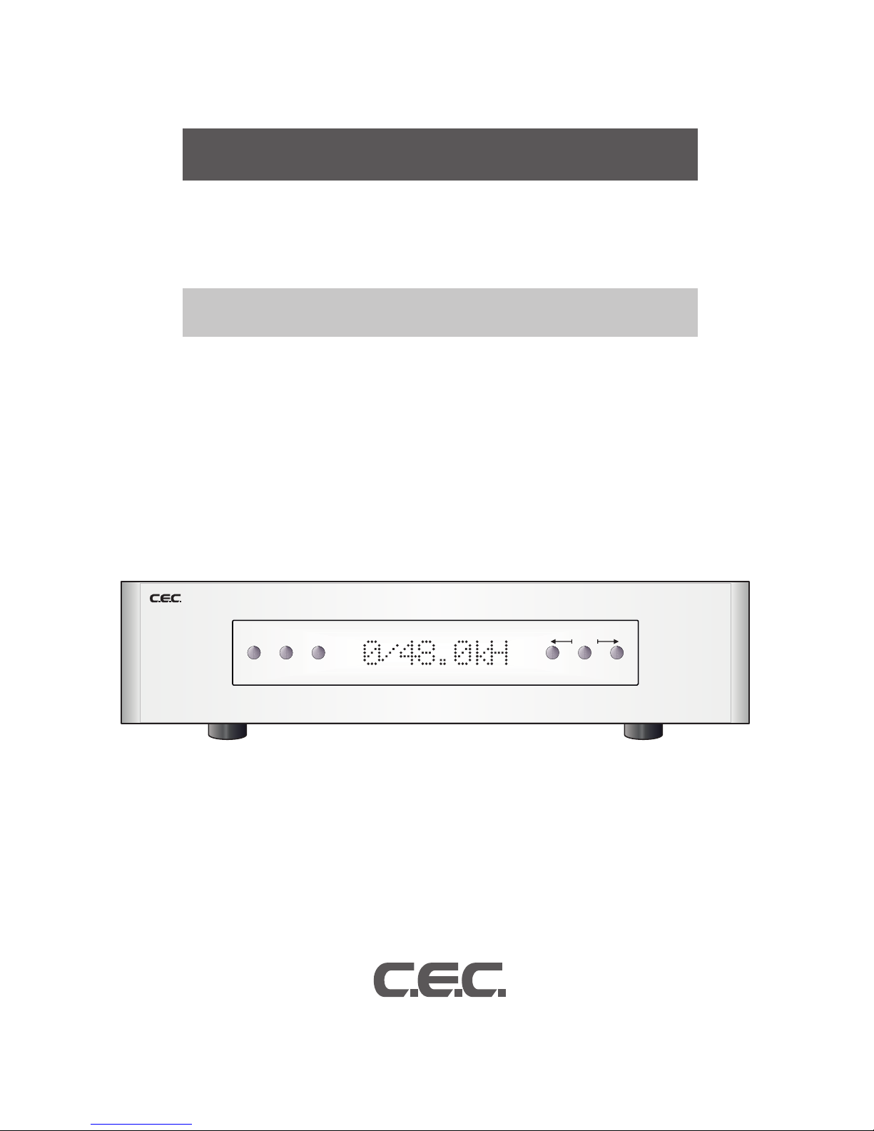
For initial power up press the main switch located on the back panel. Red LED on the front
panel next to the ON/OFF button (see Fig. 1) indicates the unit is now in STANDBY mode.
To switch the DAC on press the “ON/OFF” button on the front panel. The red standby indicator
blinks green for approx 10 sec. whilst the unit warms up. When ready, the indicator will stop
blinking and turns to green, also the last active source will be automatically selected.
The front panel display will be on while the unit is executing a command and then turns off af-
ter a short timeout period.
When an input signal is detected, the frequency and bit depth will be read out on the display.
Re-clocking
Enable this function in the user menu (see “Menu structure” below) . This very important fea-
ture of the DAC, thath allow all jitter to be removed from the input source. Data is read into a
memory and then independently read out using a ultra stable clock. When enabled, this option
will completely replace the incoming clock with an ultra low jitter TCXO based clock. The DSP
monitors the incoming sample frequency and detects standard sample rate signals, 44.1 kHz,
48 kHz, 88.2 kHz, 96 kHz, 176.4 kHz, 192 kHz, 352.8 kHz and 384 kHz. The on-board clock
then completely replaces the incoming clock. Other sampling frequencies use the incoming
clock from the source. The DSP allocates a huge internal FIFO buffer (1/2 second at 44.1),
that stores the incoming audio to decouple the incoming and outgoing data streams. Long
absolute digital silences in the music stream, such as between tracks and during pauses, are
selectively shortened or lengthened by the DSP to maintain data synchronization. This results
inasignicantdelaybetweentheaudiosourceandtheanalogaudio.Youwillnotnormallyno-
tice this delay unless video is synchronized to the audio. For this reason this feature may want
to be turned off when watching video, or the video should be delayed.
Up-sampling
Enable this function in the user menu (see “Menu structure below) thus all input signals will be
up-sampled to max resolution 32/352 or 32/384 depending on input signal. To achieve this, a
digital filter takes a look at a window of the music being played, and because that music was
received from a digital source, there are holes in it, between data bytes. The filter looks at the
shape of the signal in the window and tries to figure out what the missing data is. The bigger
the window, the better a job it does, and the bigger processor is needed. You can select the
up-sampling algorithm to use (UPS F1 or F2 in the User Menu) in the process of filling in the
gaps between the data.
Digital Filter
The digital filter is necessary because mirrored image frequencies created during the conver-
sion process must be removed. If the DAC did not have a digital filter, an analog filter with an
aggressive response must remove these image frequencies. Analog filters seriously damage
the signal by corrupting the original phase of the sound and cannot fully remove the high fre-
quency images. This results in harsh or rolled off high frequencies and poor soundstage focus.
OurDAC offerschoiceof4digital lters (F1, F2, F3 andF4),selectableintheUser Menu.
Each option provides a distinct, glorious listening experience. You may favor one or the other,
orenjoychangingthelterresponsetosuitthemusicyoulistento.
REPEAT button
Press this button to repeatedly playback all the tracks on a disc. When repeat mode is
on, the display will show the repeat indicator. Press this button again to cancel repeat
mode.
DIM button
Displaybrightnesscanbechangedindifferentve
levels. Press and hold this button on the remote
control unit for 2 seconds to dim the display. Every
2 seconds the display will change in the order
shown by the drawing bellow. Level 4 is the default
setting and brightest, and level 3 is less bright than
level 4. Level 0 means that the display is turned
off, i.e. completely dark. In the Level 0 setting it will
be returned to one brighter level 1 automatically
whenever the CD Stabilizer is removed.
Press and hold the DIM key 2 seconds again for the DARK setting after placing the CD
Stabilizer. Regardless of the current DIMMER setting it will be returned to the default in
case that the power is turned on again.
Precaution on handling the remote control unit
▷
When operating the remote control, point it towards the remote sensor on the front
panel.
▷
Make sure nothing is blocking the front panel where the remote sensor is located.
▷
Avoid exposing the remote sensor on the front panel to direct sunlight or other light
sources, as such exposure can cause malfunction.
▷
The remote control unit may malfunction when its batteries are running low. Change
the batteries to new ones of the same type if this seems to be the case.
Battery Installation/Replacement
Unscrew the six bolts on the back cover of the remote using internal hex screwdriver
size 2, and remove the back cover. Insert the provided two AAA batteries into the
compartment. Make sure that the batteries are inserted with their possitive (+) and
negative (-) poles positioned correctly, and screw the cover back on.
Precaution on handling batteries
▷
Never use different types of batteries together. Both rechargeable and non-
rechargeable batteries can be used, but the two should not be used together.
▷
If you will not be using the remote control unit for an extended period of time (more
than a month), remove the batteries to prevent leakage.
▷
If the batteries leak, use a cloth to wipe away the liquid inside the battery
compartment and replace the batteries with new ones.
▷
Do not heat or disassemble batteries, and never dispose of old batteries by throwing
theminare.Disposeofbatteriesfollowinglawsinthelocalarea
Level 4
(Default=Brightest)
Level 3
Level 2Level 1
Level 0 (=dark)
Press and hold
the 0 key 2 seconds
to dim the display

DIGITAL TO ANALOG CONVERTER DA 0 3.0 DA 0 3.0 User's Manual
12 13
Operation
Inputs
2 x COAX (RCA) connectors. Limited to 384 kHz, 24 bit data
2 x AES/EBU (XLR) connectors
2 x TOSLINK (optic) connectors. This format has limited bandwidth and
works for maximum sample rates of 192 kHz
1 x USB (optional)
Output
1 pair unbalanced RCA connectors
1 pair balanced XLR connectors
Power supply 115 or 230 V
Power consumption 30W
Dimensions WxDxH - 432x400x120 mm
Word Clock Input BNC x 1: 44.1kHz
Power Supply AC120/230V,50/60Hz(Speciedonrearpanel)
Weight 20Kg
Finish Main unit Black or Silver anodized aluminium
Specications
To turn off the DAC press the ON/OFF button. All the unit circuitry will be turned off for min-
imum power consumption leaving only a small STANDBY circuit running. However, if you
are not going to use the DAC for a long period we recommend turning it off, using the power
switch on the back panel, to save power.
Aswithallhighdelityproducts,thesoundcharacteristicchangessomewhatasitwarmsup.
Best sound will be achieved after about 15 minutes of operation.
Any time that the DA 0 3.0 DAC has not been used for a few weeks the sound may be differ-
ent. This is also normal for high resolution audio equipment. Optimum sound should return
after a few hours of operation, preferably with an audio signal.
Note that although your CEC System has been run for 72 hours at the factory, it will continue
to ”break in” for approximately 150 hours. Also be aware that many components display the
need for a new break in period after being transported in unheated cargo aircraft.
Menu structure
❶Phase +/- – switches absolute phase of the signal
❷Reclock ON/OFF – turns the reclocking feature on/off
❸Upsa ON/OFF – turn the upsampling feature on/off (when on Upsamples all input
signals to max resolution 32/352 or 32/384 depending on input signal)
❹UPS F1/F2 – Selects the upsampling algorithm to use
❺FilterF1/F2/F3/F4 –selectsthedigitallter to beused.Listenandselect the lter
that suits best to the original recording and the rest of your audio system
❻LED ON/OFF
Factory settings
❶Phase +
❷Reclock ON
❸Upsa ON
❹UPS F2
❺Filter F2
❻LED ON
Options
As digital audio is developing at very fast pace and to protect your investment in our state of
the art DAC we have provided 2 option slots that can accommodate whatever new technology
or interface becomes a standard.
Currently USB is a de facto standard for interfacing a computer to audio DAC. There are a
number of implementations and options for those as well. We constantly monitor the state of
development of all and will offer the best implementations as options for your DAC.
There are a number of other technologies that we are currently monitoring and as soon as any
of them has matured we will implement it as an option.
Please check our website regularly for updates.

DIGITAL TO ANALOG CONVERTER DA 0 3.0 DA 0 3.0 User's Manual
14 15
Notes Notes

1507-A
CEC Holdings Co., Ltd., Japan
Table of contents
Other C.E.C. Media Converter manuals